Table of Contents
Advertisement
ELGAR ELECTRONICS CORPORATION
9250 Brown Deer Road
San Diego, CA 92121-2294
1-800-733-5427
Tel: (858) 450-0085
Fax: (858) 458-0267
Email: sales@elgar.com
www.elgar.com
This document contains information proprietary to Elgar Electronics Corporation. The information contained herein is
not to be duplicated or transferred in any manner without prior written permission from Elgar Electronics Corporation.
July 19, 2002
SmartWave™
Switching
Amplifier
Operation Manual
This manual covers models:
SW5250A
SW3500A
SW1750A
©2002 by Elgar Electronics Corporation
Document No. M162001-01 Rev F
Advertisement
Table of Contents

Related Manuals for Elgar SmartWave SW5250A

Summary of Contents for Elgar SmartWave SW5250A
-
Page 1: Operation Manual
©2002 by Elgar Electronics Corporation This document contains information proprietary to Elgar Electronics Corporation. The information contained herein is not to be duplicated or transferred in any manner without prior written permission from Elgar Electronics Corporation. July 19, 2002 Document No. M162001-01 Rev F... -
Page 3: Conditions Of Warranty
Elgar non-warranty service rates. • Warranty field service is available on an emergency basis. Travel expenses (travel time, per diem expense, and related air fare) are the responsibility of the Buyer. A Buyer purchase order is required by Elgar prior to scheduling. •... - Page 4 Committed to Quality...Striving for Excellence...
- Page 5 This page intentionally left blank.
-
Page 6: Safety Notice
SAFETY NOTICE Before applying power to the system, verify that the SW Series unit is configured properly for the user’s particular application. WARNING! Hazardous voltages in excess of 280 VRMS, 600V peak may be present when covers are removed. Qualified personnel must use extreme caution when servicing this equipment. -
Page 7: Safety Symbols
All the safety instructions and advice notes are to be followed. Neither Elgar, San Diego, California, USA, nor any of the subsidiary sales organizations can accept any responsibility for personal, material or consequential injury, loss or damage that results from improper use of the equipment and accessories. -
Page 9: Table Of Contents
CONTENTS SECTION 1 GENERAL DESCRIPTION Introduction....................1-1 Input Specifications ..................1-3 Output Specifications: Normal Operation Mode..........1-3 Waveform Specifications ................1-5 Measurements (Optional) ................1-5 1.5.1 Parameters Measured............... 1-5 1.5.2 Measurement Capabilities and Accuracies ........1-6 Protection and Safety ..................1-9 Agency Requirements ................... - Page 10 Contents SW 5250A•SW 3500A•SW 1750A Pre-installation Inspection ................2-2 Installation ......................2-2 Air Intake and Exhaust ...................2-2 Installation/Dimensional Drawing ..............2-3 Input/Output Connectors ................2-6 2.7.1 BNC Connectors................2-7 2.7.2 EXT IN (External Input)..............2-7 2.7.3 DFI (Direct Fault Indicator) ..............2-8 2.7.4 IEEE 488.2..................2-9 2.7.5 Slave Connector ................2-9 2.7.6 Grounding ..................2-10 Input Power Requirements................2-10...
- Page 11 SW 5250A•SW 3500A•SW 1750A Contents Front Panel Programming Conventions............3-33 Front Panel Programming Exercises ............3-34 3.5.1 Current Inrush Example ..............3-34 3.5.2 Voltage Spike Example ..............3-38 3.5.3 Voltage Dropout Example ............... 3-42 SCPI Specification ..................3-45 SECTION 4 STANDARD WAVEFORMS LIST OF TABLES Table 2–1 Recommended Mounting Slide ..............
- Page 12 Contents SW 5250A•SW 3500A•SW 1750A LIST OF FIGURES Figure 1–1 Elgar Model SW 5250A AC Power Source (Rack Mount Version) ...1-1 Figure 2–1 Mounting Dimensions, SmartWave Front View .........2-3 Figure 2–2 Mounting Dimensions, SmartWave Top and Side Views......2-4 Figure 2–3 SmartWave Rear Panel................2-5 Figure 2–4 Parallel Connections................2-14...
-
Page 13: Section 1 General Description
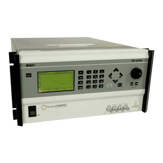
(sweeps). The unit can also generate clipped waveforms, harmonic distortion, high current inrush, and other complex waveshapes. Figure 1–1 Elgar Model SW 5250A AC Power Source (Rack Mount Version) Operation Manual... - Page 14 General Description SW 5250A•SW 3500A•SW 1750A The SmartWave model numbers are identified below: SW5250 A–1–3–2–XXX Power Options: 5250 3500 1750 Chassis Description: A = Standard High Impedance AE = Standard IEC Low Impedance M, ME, S, SE = N/A Power Conditioning Options: 1 = Rectifier USA 2 = Rectifier International 3 = PFC USA...
-
Page 15: Input Specifications
SW 5250A•SW 3500A•SW 1750A General Description The SmartWave sources are true DC as well as AC power supplies. Up to 312 VRMS are available in AC or AC+DC modes. Multi-phase models can be switched to single or three-phased operation via the front panel or the GPIB. A wide frequency range of DC or 40 Hz to 5 kHz is available for a broad array of applications. - Page 16 General Description SW 5250A•SW 3500A•SW 1750A Total Harmonic Distortion (Full Linear Load or No Load): 0.25% maximum, 40 to 100 Hz; 0.5% maximum to 500 Hz; and 1% maximum to 1 kHz plus 1%/kHz to 5 kHz. AC Noise Level: >60 dB RMS below full output (sine wave, 40 to 500 Hz). Amplitude Stability With Remote Sense: ±0.1% of full scale over 24 hours at constant line, load and temperature.
-
Page 17: Waveform Specifications
SW 5250A•SW 3500A•SW 1750A General Description Waveform Specifications Waveshape Libraries: 50 factory-supplied in flash memory; storage available for up to 50 user created in non-volatile RAM. User Created Setups: A total of 100 steady-state waveforms, consisting of parameters such as waveshapes from the libraries plus amplitude, frequency, phase angle and current limit. -
Page 18: Measurement Capabilities And Accuracies
General Description SW 5250A•SW 3500A•SW 1750A 1.5.2 Measurement Capabilities and Accuracies 1.5.2.1 Measurement Capability 4½ Digit Analog to Digital Measurement System Temperature Range for Specified Accuracy: 25°C ±5°C. Operating Temperature Range: 0°C to 45°C (32°F to 113°F). 1.5.2.2 Phase to Neutral RMS Voltage Measurement Valid for phases A, B and C (use phase A for Parallel Mode). - Page 19 SW 5250A•SW 3500A•SW 1750A General Description 1.5.2.5 Peak Current Measurement Valid for phases A, B, and C (use phase A for Parallel Mode). Range 1: 0A to 28A; 3-phase mode, 312V range. Range 2: 0A to 56A; 3-phase mode, 156V range. Range 3: 0A to 84A;...
- Page 20 General Description SW 5250A•SW 3500A•SW 1750A 1.5.2.8 Power Factor Calculation Valid for phases A, B, C, and TOTAL (use phase A for Parallel Mode). The Power Factor is calculated from the Power and VA measurements. Phase powers are measured then the total power is calculated; phase VAs are measured then the total VA is calculated.
-
Page 21: Protection And Safety
SW 5250A•SW 3500A•SW 1750A General Description Protection and Safety Overvoltage Shutdown: Programmable for 15V to 255V peak, 156V range; 30V to 510V peak, 312V range. Undervoltage Shutdown: Automatic, not programmable. Programmable Current Limit Shutdown: Can be set to 1% of range; 0.5A to 13A for 156V range, 0.5A to 6.5A for 312V range. -
Page 22: Physical Specifications (All Models)
General Description SW 5250A•SW 3500A•SW 1750A Physical Specifications (All Models) Height: 8.75" (222 mm) Width: 19" (483 mm) Depth: 23.5" (597 mm) Weight: SW 5250A - 126.5 lbs. (57.2 kg) SW 3500A - 100 lbs. (45.4 kg) SW 1750A - 73 lbs. (33.1 kg) Cooling: Air is drawn in from the top and sides and exhausted through the rear of the chassis. - Page 23 SW 5250A•SW 3500A•SW 1750A General Description • SYNC OUT. User programmed for: Cycle Start, all cycles Segment Start. all segments Segment Start, selected segments For loads ≥2 kΩ: Vout ≤1V Low State; Vout ≥2.4V High State; Negative edge is at 0° ±30 µs. •...
-
Page 24: Options
General Description SW 5250A•SW 3500A•SW 1750A • External Gain Control 0 to ±7.07 VDC provides zero to full scale programmed voltage output (±2% of full scale output). • External Input Impedance ≥30 kΩ. • System Firmware System firmware is stored in flash memory. This makes it possible to upgrade the firmware without disassembling or returning the unit. -
Page 25: Glossary Of Technical Terms
SW 5250A•SW 3500A•SW 1750A General Description 1.12 Glossary of Technical Terms 1.12.1 RMS Servo An RMS Servo uses a feedback scheme to regulate the RMS value of the output voltage or current by adjusting the RMS value of the reference input signal. For example, if the output sags under load by 1%, the reference input is increased by 1%. -
Page 26: X-Load
General Description SW 5250A•SW 3500A•SW 1750A The SmartWave allows you to select boost On or Off. In some applications, the transient response time associated with the boost function is unacceptable, but tight RMS regulation is still required. Boost should be turned off in such cases. An example is when a sequence is programmed with various sags and surges which must have sharp transitions from one RMS voltage to another. -
Page 27: Section 2 Installation
SECTION 2 INSTALLATION Introduction The Elgar Model SW 5250A, SW 3500A, or SW 1750A has been fully calibrated and tested prior to shipment. The instrument is ready for immediate use upon receipt. WARNING! The SmartWave unit weighs 73–126.5 lbs. (33.1–57.2 kg), depending on the model. -
Page 28: Pre-Installation Inspection
Installation SW 5250A•SW 3500A•SW 1750A Pre-installation Inspection Perform a visual inspection of the instrument when it is removed from the shipping container. Check for shipping damage such as dents, scratches, distortion, and damaged connectors. Installation The SmartWave unit is 8.75" (222 mm) high and is designed to be installed in a standard 19"... -
Page 29: Installation/Dimensional Drawing
SW 5250A•SW 3500A•SW 1750A Installation Installation/Dimensional Drawing Refer to Figure 2–1 and Figure 2–2 for information on outline and mounting dimensions of the unit and customer wiring conduit details. Refer to Figure 2–3 and Table 2–2 through Table 2–6 for rear panel connector information. TYPE MANUFACTURER PART NUMBER... -
Page 30: Figure 2-2 Mounting Dimensions, Smartwave Top And Side Views
Installation SW 5250A•SW 3500A•SW 1750A Figure 2–2 Mounting Dimensions, SmartWave Top and Side Views Operation Manual... -
Page 31: Figure 2-3 Smartwave Rear Panel
SW 5250A•SW 3500A•SW 1750A Installation Figure 2–3 SmartWave Rear Panel Operation Manual... -
Page 32: Input/Output Connectors
Table 2–2 provides a listing of the SW input and output connectors and other data. Table 2–3 through Table 2–6 provide specific pinout information. NOTE: The RS232 AND AUX OUT connectors (Figure 2–3, Items 4 and 8, respectively) are Elgar proprietary; thus, the pinouts will not be provided. ITEM # NAME... -
Page 33: Bnc Connectors
SW 5250A•SW 3500A•SW 1750A Installation 2.7.1 BNC Connectors The diagram below illustrates the signal and return connections. Refer to Figure 2–3, Items 1 and 2. 2.7.2 EXT IN (External Input) Refer to Figure 2–3, Item 3. PIN # MNEMONIC LEVEL SHIELD CHASSIS SHIELD... -
Page 34: Dfi (Direct Fault Indicator)
Installation SW 5250A•SW 3500A•SW 1750A 2.7.3 DFI (Direct Fault Indicator) The DFI connector on the rear panel has both input and output functionality. The DFI Output Relay indicates a shutdown fault has occurred on the SW. It is a SPST reed relay with rear panel connections to the normally closed output contacts. -
Page 35: Ieee 488.2
SW 5250A•SW 3500A•SW 1750A Installation 2.7.4 IEEE 488.2 Refer to Figure 2–3, Item 6. PIN # MNEMONIC PIN # MNEMONIC PIN # MNEMONIC DIO1 DIO2 GND (TW PAIR W/DAV) DIO3 GND (TW PAIR W/NRFD) DIO4 SHIELD GND (TW PAIR W/NDAC) DIO5 GND (TW PAIR W/IFC) DIO6... -
Page 36: Grounding
Installation SW 5250A•SW 3500A•SW 1750A 2.7.6 Grounding The three waveform outputs (TRIGGER OUT, CLOCK & LOCK, SYNC OUT) share the same ground. This ground should not exceed ±20V Peak from chassis ground. If possible, this ground should be connected to the chassis. DFI and IEEE 488.2 share the same signal ground. -
Page 37: Table 2-7 Input Currents For 3-Phase Input Power
SW 5250A•SW 3500A•SW 1750A Installation MAXIMUM MAXIMUM F1-F3 RECOMMENDED LINE NEUTRAL FUSE CIRCUIT BREAKER CURRENT CURRENT RATING RATING (MAX.) SW 5250A (SW 5250M, SW 5250S) 25A RMS Not Required 40A RMS INTL 13A RMS 13A RMS 20A RMS RECT 39A RMS Not Required 50A RMS RECT... -
Page 38: 187 To 264 Vrms L-L 3-Phase Operation (3-Wire Usa)
Installation SW 5250A•SW 3500A•SW 1750A 2.8.1 187 to 264 VRMS L–L 3-Phase Operation (3-Wire USA) Connect the input wires to the phase A (F1), B (F2), and C (F3) input fuse terminals (no Neutral is required). Ensure that the chassis safety ground is also connected. Use cables with ratings equal to or greater than the current rating listed on the unit or in Table 2–7. -
Page 39: Output Connections To The Load
SW 5250A•SW 3500A•SW 1750A Installation Output Connections to the Load 2.9.1 SW 5250A Output Connections The Model SW 5250A can power 1-phase, 2-phase and 3-phase loads. Local or remote sensing can be used; if no sense lines are connected, the unit automatically reverts to local sense. -
Page 40: Figure 2-4 Parallel Connections
Installation SW 5250A•SW 3500A•SW 1750A Figure 2–4 Parallel Connections Figure 2–5 Sense Lead Connections for 3-Phase Output 2-14 Operation Manual... -
Page 41: Sw 3500A And Sw 1750A Output Connections
Thus, this guide applies equally to the input cable and output cable for this Elgar instrument and application loads. Power cables must be able to safely carry maximum load current without overheating or causing insulation destruction. -
Page 42: Table 2-9 Recommended Wire Gauge Selection Guide
Installation SW 5250A•SW 3500A•SW 1750A Such a loss directly detracts from the quality performance specifications of this Elgar instrument. Frequently, these codes do not consider bundles of wire within a cable arrangement. In high performance applications, as in motor start-up and associated inrush/ transient currents, additional consideration is required. - Page 43 SW 5250A•SW 3500A•SW 1750A Installation The following notes apply to Table 2–9 and to the power cable definition: The above figures are based upon insulated copper conductors at 25°C (77°F), two current carrying conductors in the cable plus a safety (chassis) ground. Columns 3 and 4 refer to “one way”...
- Page 44 Capability 3 to 6 Above 6 The preferred insulation material is application dependent. Elgar's recommend- ation is any flame retardant, heat resistant, moisture resistant thermoplastic insulation rated to a nominal 75°C (167°F). Voltage breakdown must exceed the combined effects of: •...
-
Page 45: Section 3 Operation
SECTION 3 OPERATION Introduction The following is an overview of the controls and display for the SmartWave unit. Context-sensitive help is available from the front panel by pressing the Help key. Front Panel Controls The SW front panel is used for programming and data entry in local mode operation. The front panel is shown in Figure 3–1, followed by a description of each of the controls. - Page 46 When power is turned on, the unit goes through the power up cycle. This cycle may last between 30 seconds and five minutes, depending on the amount of software that needs to be loaded and conditioned. The Elgar logo will be displayed during the power up cycle.
-
Page 47: Menus
SW 5250A•SW 3500A•SW 1750A Operation KEYPAD. The 12-key keypad is used to enter numeric values (0 through 9), a decimal point (when required), and to change the polarity of the selection via the +/- key. For example, to enter an amplitude value of “-139.2,” enter 1, 3, 9, decimal point, 2;... -
Page 48: Main Menu
Operation SW 5250A•SW 3500A•SW 1750A • Use the Enter and Menu keys or the Right/Left Arrow keys to move between the menus. • Use the Up/Down Arrow keys to cycle through the items within a specific menu. • When you select an item, you can enter data in two ways: (1) Use the keypad to type in the data, or (2) press the Enter key to place a box around the value area, then use the Up/Down Arrow keys or the Knob to select the data to be entered. -
Page 49: Program Menu
SW 5250A•SW 3500A•SW 1750A Operation 3.3.2 PROGRAM Menu The PROGRAM menu allows you to: • Select a phase • Program amplitude • Program current limit • Program frequency • Program phase offset (phase offset represents a phase lead with respect to the internal reference) •... - Page 50 Operation SW 5250A•SW 3500A•SW 1750A Reference Section 3.4, Front Panel Programming Conventions. There is only one frequency setting for all three phases. Changing the frequency of one phase changes the frequency for all phases. The SW can accept only positive numbers when programming phase angle offset.
- Page 51 SW 5250A•SW 3500A•SW 1750A Operation 3.3.2.2 Front Panel Store/Recall The current state of the SW can be saved and restored using the Front Panel Store/Recall feature. The following Program Menu parameters are affected: • Amplitude • Current Limit • Frequency •...
-
Page 52: Measure Menu
Operation SW 5250A•SW 3500A•SW 1750A 3.3.3 MEASURE Menu If equipped with the Test and Measurement option, the MEASURE menu allows you to: • Measure voltage (RMS) • Measure current (RMS) • Measure frequency • Measure phase angle (referenced to a master) •... -
Page 53: Waveform Menu
SW 5250A•SW 3500A•SW 1750A Operation 3.3.4 WAVEFORM Menu The WAVEFORM menu allows you to perform a variety of actions on waveshapes and waveforms, including the creation of a new waveform based on a waveshape in memory. The waveshapes and waveforms are limited to spikes, dropouts, sags and surges of existing waveforms in the scratchpad area. - Page 54 Operation SW 5250A•SW 3500A•SW 1750A 3.3.4.1 LOAD Sub-Menu The WAVEFORM menu allows you to LOAD an existing waveform from non-volatile or flash memory to the waveform scratchpad. Any existing information in the scratchpad is erased when a new waveform is loaded. WAVEFORM OUTPUT [OFF] Name...
- Page 55 SW 5250A•SW 3500A•SW 1750A Operation 3.3.4.2 EDIT Sub-Menu The WAVEFORM menu allows you to EDIT a waveform in the scratchpad. WAVEFORM OUTPUT [OFF] LOAD FREQ EDIT Vrms VIEW START SAVE TIME DELETE STOP AMPL EDIT Sub-Menu Status and Information Data: Menu Item Status and Information Line Range...
- Page 56 Operation SW 5250A•SW 3500A•SW 1750A 3.3.4.3 VIEW Sub-Menu The WAVEFORM menu allows you to VIEW a waveform: WAVEFORM OUTPUT [OFF] LOAD EDIT VIEW SAVE DELETE Selecting VIEW will display the waveform in the scratchpad as shown below. WAVEFORM OUTPUT [OFF] Basic display after selecting VIEW The minimum and maximum Vpeak values displayed on the vertical axis (either -442 to +442 or -221 to +221) are based on...
- Page 57 SW 5250A•SW 3500A•SW 1750A Operation 3.3.4.4 SAVE Sub-Menu The WAVEFORM menu allows you to assign a name to a new waveform and SAVE it from the scratchpad to non-volatile memory. Use the Up/Down Arrow keys or the Knob to enter the custom waveform name. Press the Right Arrow key to proceed to the next character;...
- Page 58 Operation SW 5250A•SW 3500A•SW 1750A 3.3.4.5 DELETE Sub-Menu The WAVEFORM menu allows you to DELETE a waveform stored in non-volatile memory. ALL USER WAVEFORMS - Erases the 50 user waveform locations in non-volatile RAM. Any user waveforms currently running will not be deleted. INITIALIZE MEMORY - Resets the waveform library to the factory settings.
-
Page 59: Sequence Menu
SW 5250A•SW 3500A•SW 1750A Operation 3.3.5 SEQUENCE Menu The SEQUENCE menu allows you to create, edit, and execute a sequence. SEQ MENU OUTPUT [OFF] LOAD EDIT SAVE DELETE EXECUTE 3.3.5.1 LOAD Sub-Menu The SEQUENCE menu allows you to LOAD an existing sequence from non-volatile or flash memory to the sequence scratchpad. - Page 60 Operation SW 5250A•SW 3500A•SW 1750A 3.3.5.2 EDIT Sub-Menu The SEQUENCE menu allows you to EDIT a sequence in the scratchpad. Frequency or amplitude can be ramped over the segment duration. SEQ EDIT OUTPUT [OFF] FREQ 60.00 TIME 0.00 θ AMPL FUNC ANGL 0.00...
- Page 61 SW 5250A•SW 3500A•SW 1750A Operation • A ramp must always consist of at least two segments so that starting and ending values can be specified. • Ramps can be increasing or decreasing in value. • Voltage and frequency ramping is available; phase angles cannot use the ramping function.
- Page 62 Operation SW 5250A•SW 3500A•SW 1750A The “CYCLES” Edit Field When the field select cursor is at the CYCLES field, pressing F1 will toggle the SYNC SELECT symbol “*”. This is a flag used in conjunction with the SYNC field of the Sequence Execute menu;...
- Page 63 SW 5250A•SW 3500A•SW 1750A Operation SAVE Sub-Menu Status and Information Data: Menu Item Status and Information Line NAME [– > = next char, < – = backsp] SAVE [store sequence in library] 3.3.5.4 DELETE Sub-Menu The SEQUENCE menu allows you to DELETE a sequence stored in non-volatile memory.
- Page 64 Operation SW 5250A•SW 3500A•SW 1750A 3.3.5.5 EXECUTE Sub-Menu The SEQUENCE EXECUTE sub-menu allows the selection of the start, run, and stop modes of a sequence. The front panel operation is defined here, but all modes are also available via the GPIB. A sequence can be executed in any combination of the following modes: •...
- Page 65 SW 5250A•SW 3500A•SW 1750A Operation SELECTIO PURPOSE Loads a sequence for execution from the sequence library or the sequence LOAD SEQ scratchpad. When running under GPIB control, the Event Status Register and serial polling can be used to indicate when the sequence loading is complete.
-
Page 66: Table 3-1 Sequence Execute Menu
Operation SW 5250A•SW 3500A•SW 1750A Table 3–1 Sequence Execute Menu 3-22 Operation Manual... -
Page 67: Instr (Instrument) Menu
SW 5250A•SW 3500A•SW 1750A Operation 3.3.6 INSTR (Instrument) Menu The INSTR menu allows you to: • Set the output range (156 or 312 volts). • Select either AC or AC+DC coupling. • Select current limit mode, either shutdown, foldback or time-out mode (foldback for the time specified in the ITIMO field then shutdown mode). -
Page 68: System Menu
Operation SW 5250A•SW 3500A•SW 1750A 3.3.7 SYSTEM Menu 3.3.7.1 USER Sub-Menu The SYSTEM USER sub-menu allows you to: • Configure power up values. • Execute the unit’s self-test. • Enable/disable hint messages. • Enable/disable the sync output in the Program mode (i.e., when a sequence is not running). -
Page 69: Table 3-2 Self-Test Results Definitions
SW 5250A•SW 3500A•SW 1750A Operation SYNC OUT selects the output sync signal to ON, OFF or EVENT. In the ON position, the signal is driven by the output frequency of the waveform, or sequence settings. In the EVENT position, a pulse will be generated for any change in VOLT, CURR, FREQ, PHASE or WAVEFORM. - Page 70 Operation SW 5250A•SW 3500A•SW 1750A 3.3.7.2 COMM Sub-Menu The SYSTEM COMM (Communications) sub-menu allows you to: • Configure the GPIB address and display remote status. • Display firmware version information. SYSTEM OUTPUT [OFF] USER GPIB ADDR COMM ECDI VER X.XX DWSB VER X.XX EXTERNAL...
- Page 71 SW 5250A•SW 3500A•SW 1750A Operation 3.3.7.3 EXTERNAL Sub-Menu The SYSTEM EXTERNAL sub-menu allows you to: • Select external modes of operation (Direct Input, External Modulation, External Gain, and Clock/Lock). • Select alternate compensation (X-LOAD). • Select Low Frequency for operation below 40 Hz when using an external input. CAUTION! Damage to the equipment may occur if input frequency requirements are violated (DC, 40–5000 Hz).
-
Page 72: Table 3-3 System External Menu
Operation SW 5250A•SW 3500A•SW 1750A SELECTION PURPOSE Amplitude modulation of an output waveform is possible via an input EXT MOD (External signal from the rear panel. Input of 0-5 Vrms corresponds to a modulation Amplitude of 0-20%. To allow for the modulation voltage, the maximum prog- rammed voltage is 130 Vrms in low range, and 260 Vrms in high range. -
Page 73: Table 3-4 Fault Register Bit Definitions
SW 5250A•SW 3500A•SW 1750A Operation 3.3.7.4 FAULTS Sub-Menu Pressing <Enter> to select FAULTS will display a list of logged fault conditions LOG1 - LOG6. These are three 8-bit registers used to troubleshoot errors that cause the system to shut down. Fault register definitions are available through the Help screens of the SmartWave unit. -
Page 74: Table 3-5 Fault Description And Action (Fr1)
Operation SW 5250A•SW 3500A•SW 1750A Although the DFI Fault is not included in the fault history log, any of the faults will cause a DFI error to occur. When a DFI fault is tripped, either because one of the faults above or a fault external to the SW, the output relay is opened, VPROGRAM is set to zero, and an error message is displayed. -
Page 75: Table 3-6 Fault Description And Action (Fr2)
SW 5250A•SW 3500A•SW 1750A Operation FAULT REGISTER 2 F4:OT Monitors power stage heat sink temperatures. Action: Opens relays, displays error message for 30 seconds, then shuts off SW system. F2:OV Indicates that the internal DC bus has pumped up to an unacceptable level (due to sinking power rather than sourcing, i.e., attempting to discharge a very large capacitor into the SW output too quickly). - Page 76 Operation SW 5250A•SW 3500A•SW 1750A 3.3.7.5 CONFIG Sub-Menu Pressing <Enter> to select CONFIG will display the System Configuration options. BOOST - Allows the Servo Boost circuit to be disabled during non-sequence operation. This option is important when running a sequence at low voltage levels. See Section 1.12.2, Servo Boost, for a full explanation of the Boost function.
-
Page 77: Front Panel Programming Conventions
SW 5250A•SW 3500A•SW 1750A Operation Front Panel Programming Conventions • When programming an amplitude in the Program Menu, Sequence Edit Menu, or remotely over the GPIB, the Amplitude field is checked against the Function (Waveform) field for positive or negative amplitude; that is, the function polarity is used to validate the amplitude input value. -
Page 78: Front Panel Programming Exercises
Operation SW 5250A•SW 3500A•SW 1750A Front Panel Programming Exercises 3.5.1 Current Inrush Example This example illustrates programming the SW to simulate a current inrush waveform that is 0V between 0° and 90°, then instantaneously jumps from 0V to 120V at 90°. At the MAIN MENU, use either the Knob or the Up/Down Arrow keys to select the WAVEFORM menu, then either press the Enter key or the Right Arrow key. - Page 79 SW 5250A•SW 3500A•SW 1750A Operation WAVEFORM OUTPUT [OFF] 60.00 LOAD FREQ 120.00 EDIT Vrms 0.00 VIEW START 4.17 SAVE TIME 90.00 DELETE STOP 0.00 AMPL Use either the Knob or the Up/Down Arrow keys to select FREQ. The frequency is normally defaulted at 60 Hz with all other values set to 0. On the keypad, enter 6, 0, decimal point, 0, 0, then press <Enter>...
- Page 80 Operation SW 5250A•SW 3500A•SW 1750A Select VIEW, then press <Enter> to view the waveform. A waveform similar to the one illustrated below should be displayed on the LCD. WAVEFORM OUTPUT [OFF] To display the waveform on the front panel phase A output: Return to the MAIN MENU by pressing <Menu>...
- Page 81 SW 5250A•SW 3500A•SW 1750A Operation While still in the PHASE A sub-menu: Select AMPL (amplitude) with the Knob or Arrow Keys. Enter 120 with the keypad to set the amplitude at 120 volts, then press <Enter>. The inrush waveform will now be displayed on Phase A output on the front panel.
-
Page 82: Voltage Spike Example
Operation SW 5250A•SW 3500A•SW 1750A 3.5.2 Voltage Spike Example This example illustrates programming the SW for a voltage spike on a 150V sine waveform that starts at 30° and ends at 50° with an amplitude of 220.6 volts. MAIN MENU OUTPUT [OFF] PROGRAM MEASURE... - Page 83 SW 5250A•SW 3500A•SW 1750A Operation WAVEFORM OUTPUT [OFF] LOAD FUNC Sine EDIT VIEW SAVE DELETE Displays library of waveforms Press <Enter> to load the sine waveshape into scratchpad memory. The message, [waveform successfully loaded], will indicate that the waveform is now in scratchpad memory.
- Page 84 Operation SW 5250A•SW 3500A•SW 1750A Select START. Enter 30 using the keypad, then press <Enter> to set the starting phase angle to 30°. Select STOP. Enter 50 using the keypad for an ending phase angle of 50°, then press <Enter>. Note that the instrument automatically calculates the TIME (in this case, 0.93 ms).
- Page 85 SW 5250A•SW 3500A•SW 1750A Operation To retain the waveshape and display it on Phase A output on the front panel: Return to the MAIN MENU by pressing <Menu> twice. Select the PROGRAM Menu, then press <Enter>. MAIN MENU OUTPUT [OFF] PROGRAM PHASE A MEASURE...
-
Page 86: Voltage Dropout Example
Operation SW 5250A•SW 3500A•SW 1750A 3.5.3 Voltage Dropout Example This example illustrates programming the SW for a voltage dropout on a 120V sine waveform that starts at 45° with a duration of 1 millisecond and an amplitude of 10 volts. MAIN MENU OUTPUT [OFF] PROGRAM... - Page 87 SW 5250A•SW 3500A•SW 1750A Operation WAVEFORM OUTPUT [OFF] LOAD FUNC Sine EDIT VIEW SAVE DELETE Displays library of waveforms Press <Enter> to load the sine waveshape into scratchpad memory. The message, [waveform successfully loaded], will indicate that the waveform is now in scratchpad memory.
- Page 88 Operation SW 5250A•SW 3500A•SW 1750A Select START. Using the keypad, enter 45, then press <Enter> to set the starting phase angle to 45°. Select TIME, enter 1 for a duration of 1 millisecond, then press <Enter>. Note that the instrument automatically calculates the STOP phase angle value (in this case, 66.6°).
-
Page 89: Scpi Specification
Phase A of the oscilloscope. Press <Menu> or the Left Arrow key to return to the MAIN MENU. SCPI Specification Refer to the SmartWave™ Switching Amplifier SCPI Programming Manual (Elgar Document No. M162000-03). Operation Manual 3-45... - Page 91 SECTION 4 STANDARD WAVEFORMS The following standard waveforms are provided in the SW Series: SCALE FREQUENCY NAME DESCRIPTION FACTOR RANGE Clip0 A sine wave with the positive halfcycle clipped at 0V from 40-5000 Hz 50 to 130° ClipPos A sine wave with the positive halfcycle clipped from 40-5000 Hz 50 to 130°...
- Page 92 Standard Waveforms SW 5250A•SW 3500A•SW 1750A SCALE FREQUENCY NAME DESCRIPTION FACTOR RANGE FlatTp15 Flat-top sine wave with 15% distortion (true rms) 0.8545 40-5000 Hz FlatTp20 Flat-top sine wave with 20% distortion (true rms) 0.8251 40-5000 Hz Four3 Fourier square wave with 1st and 3rd harmonics 0.8946 40-5000 Hz (true rms)
- Page 93 SW 5250A•SW 3500A•SW 1750A Standard Waveforms SCALE FREQUENCY NAME DESCRIPTION FACTOR RANGE Spike250 Sine with spikes at peaks. Spikes are from 85 to 95° 1.4731 40-5000 Hz and calibrated to be 250Vpeak when programmed to 120Vrms Spike300 Sine with spikes at peaks. Spikes are from 85 to 95° 1.7678 40-5000 Hz and calibrated to be 300Vpeak when programmed to...
- Page 94 Standard Waveforms SW 5250A•SW 3500A•SW 1750A This page intentionally left blank. Operation Manual...
Need help?
Do you have a question about the SmartWave SW5250A and is the answer not in the manual?
Questions and answers