Sign In
Upload
Manuals
Brands
Elgar Manuals
Amplifier
SmartWave SW5250A
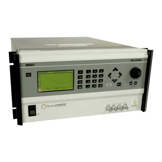
User Manuals: Elgar SmartWave SW5250A AC Power Source
Manuals and User Guides for Elgar SmartWave SW5250A AC Power Source. We have
1
Elgar SmartWave SW5250A AC Power Source manual available for free PDF download: Operation Manual
Elgar SmartWave SW5250A Operation Manual (94 pages)
Switching Amplifier
Brand:
Elgar
| Category:
Amplifier
| Size: 1 MB
Table of Contents
Conditions of Warranty
3
Safety Notice
6
Safety Symbols
7
Table of Contents
9
List of Figures
13
Section 1 General Description
13
Introduction
13
Figure 1-1 Elgar Model SW 5250A AC Power Source (Rack Mount Version)
13
Input Specifications
15
Output Specifications: Normal Operation Mode
15
Waveform Specifications
17
Measurements (Optional)
17
Parameters Measured
17
Measurement Capabilities and Accuracies
18
Protection and Safety
21
Agency Requirements
21
Physical Specifications (All Models)
22
Environmental Data
22
Other Standard Features
22
Options
24
Glossary of Technical Terms
25
RMS Servo
25
Servo Boost
25
X-Load
26
Section 2 Installation
27
Introduction
27
Unpacking
27
Pre-Installation Inspection
28
Installation
28
Air Intake and Exhaust
28
List of Tables
29
Installation/Dimensional Drawing
29
Table 2-1 Recommended Mounting Slide
29
Figure 2-1 Mounting Dimensions, Smartwave Front View
29
Figure 2-2 Mounting Dimensions, Smartwave Top and Side Views
30
Figure 2-3 Smartwave Rear Panel
31
Input/Output Connectors
32
Table 2-2 SW Input/Output Connectors (See Figure 2-3)
32
BNC Connectors
33
EXT in (External Input)
33
Table 2-3 EXT in Connector Pinout
33
DFI (Direct Fault Indicator)
34
Table 2-4 DFI Connector Pinout
34
Ieee 488.2
35
Slave Connector
35
Table 2-5 IEEE 488.2 Connector Pinout
35
Table 2-6 Slave Connector Pinout
35
Grounding
36
Input Power Requirements
36
Table 2-7 Input Currents for 3-Phase Input Power
37
Table 2-8 Single-Phase Input Configurations
37
187 To 264 VRMS L-L 3-Phase Operation (3-Wire USA)
38
342 To 457 VRMS L-L 3-Phase Operation (4-Wire INTL)
38
Single-Phase Input Connections
38
Output Connections to the Load
39
SW 5250A Output Connections
39
Figure 2-4 Parallel Connections
40
Figure 2-5 Sense Lead Connections for 3-Phase Output
40
SW 3500A and SW 1750A Output Connections
41
Wiring of Unit
41
Wire Gauge Selection
41
Table 2-9 Recommended Wire Gauge Selection Guide
42
Section 3 Operation
45
Introduction
45
Front Panel Controls
45
Figure 3-1 Front Panel Controls (SW 5250A)
45
Menus
47
Main Menu
48
PROGRAM Menu
49
MEASURE Menu
52
WAVEFORM Menu
53
SEQUENCE Menu
59
Table 3-1 Sequence Execute Menu
66
INSTR (Instrument) Menu
67
SYSTEM Menu
68
Table 3-2 SELF-TEST Results Definitions
69
Table 3-3 System External Menu
72
Table 3-4 Fault Register Bit Definitions
73
Table 3-5 Fault Description and Action (FR1)
74
Table 3-6 Fault Description and Action (FR2)
75
Table 3-7 Fault Description and Action (FR3)
75
Front Panel Programming Conventions
77
Front Panel Programming Exercises
78
Current Inrush Example
78
Voltage Spike Example
82
Voltage Dropout Example
86
SCPI Specification
89
Advertisement
Advertisement
Related Products
Elgar SW 5550AE
Elgar SmartWave SW3500A
Elgar SmartWave SW1750A
Elgar SW 3700AE
Elgar SW 1850AE
Elgar SmartWave SW 15750
Elgar SmartWave SW 10500
Elgar SmartWave SW 21000
Elgar Sorensen DCS Series
Elgar Categories
AC Power Distribution
Power Supply
Amplifier
UPS
Control Unit
More Elgar Manuals
Login
Sign In
OR
Sign in with Facebook
Sign in with Google
Upload manual
Upload from disk
Upload from URL