Table of Contents
Advertisement
Quick Links
Instruction Manual
D103545X012
Fisherr Control-Disk™ NPS 14-36 CL150-300
High-Performance Butterfly Valve
Contents
. . . . . . . . . . . . . . . . . . . . . . . . . . . . . . . . .
Scope of Manual
. . . . . . . . . . . . . . . . . . . . . . . . . . . . .
. . . . . . . . . . . . . . . . . . . . . . . . . . . . . . . . .
. . . . . . . . . . . . . . . . . . . . . . . . . . . . . . .
. . . . . . . . . . . . . . . . . . . . . . . . . . . . . . . . . . .
. . . . . . . . . . . . . . . . . . . . . . . . . . . .
. . . . . . . . . . . . . . . . . . . . . . . . . . .
. . . . . . . . . . . . . . . . . . . . . . . . . . . . . . . .
. . . . . . . . . . . . . . . . . . . . . . . .
. . . . . . . . . . . . . . . . . . . . . . . . .
. . . . . . . . . . . . . . . . . . . . . . . . . . .
. . . . . . . . . . . . . . . . . . . . . . . . . . . . . .
. . . . . . . . . . . . . . . . . . . . . . . . . . . .
. . . . . . . . . . . . . . . . . . . . . . . . . . . . . . .
. . . . . . . . . . . . . . . . . . . . . . . . . . . . . . . . . . .
Introduction
Scope of Manual
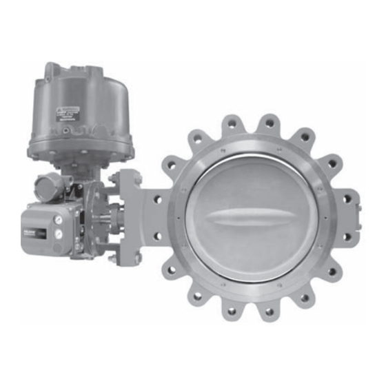
This instruction manual includes installation, maintenance, and parts ordering information for NPS 14 through 36,
CL150-300 Control-Disk High-Performance Butterfly Valves (see figure 1). Refer to separate instruction manuals for
information covering the actuator and accessories.
Do not install, operate, or maintain Control-Disk valves without being fully trained and qualified in valve, actuator, and
accessory installation, operation, and maintenance. To avoid personal injury or property damage, it is important to
carefully read, understand, and follow all the contents of this manual, including all safety cautions and warnings. If you
have any questions about these instructions, contact your Emerson Process Management sales office before
proceeding.
Unless otherwise noted, all NACE references are to NACE MR0175-2002.
www.Fisher.com
. . . . . . . . . . . . . . . . . . . . .
. . . . . . . . . . . . . . . . . .
. . . . . .
. . . . . . . . . .
. . . . . . . . . . . . .
. . . . . . . . . . . . .
. . . . . . . . . . . . .
Figure 1. Fisher Control-Disk Valve with 1061
Actuator and FIELDVUE™ DVC6020 Digital Valve
1
Controller
1
2
2
3
4
4
6
7
9
11
11
11
13
13
14
15
16
18
20
20
22
Control-Disk NPS 14-36
April 2011
Advertisement
Table of Contents

Related Manuals for Emerson Fisher Control-Disk NPS 14 CL150


Summary of Contents for Emerson Fisher Control-Disk NPS 14 CL150
-
Page 1: Table Of Contents
To avoid personal injury or property damage, it is important to carefully read, understand, and follow all the contents of this manual, including all safety cautions and warnings. If you have any questions about these instructions, contact your Emerson Process Management sales office before proceeding. -
Page 2: Description
ASME B16.5 CL150 and CL300 raised‐face flanges only) (bubble‐tight). Fire Tested per API 607 Rev. 4. NPS 30 to 36: Valve bodies are designed for For cryogenic seal applications, consult your Emerson installation between ASME B16.47 CL150 and CL300 Process Management sales office raised‐face flanges... -
Page 3: Installation
Cryogenic Seal Ring Contact your Emerson Process Management sales office 1. NACE trim constructions are available; consult your Emerson Process Management sales office. 2. PEEK stands for poly‐ether‐ether‐ketone. 3. For a complete material description, contact your Emerson Process Management sales office. -
Page 4: Valve Orientation
Emerson Process Management sales office. 1. Isolate the control valve from the line pressure, release pressure from both sides of the valve body, and drain the process media from both sides of the valve. - Page 5 1. NPS 14 to 24 face‐to‐face dimensions are in compliance with MSS SP68 and API 609 specifications. 2. Minimum I.D. is the minimum pipe or flange I.D. required for disk swing clearance. 3. Contact your Emerson Process Management sales office for information. Table 4. Valve Body Data, CL300 SHAFT DIAMETER AT FACE‐TO‐FACE...
-
Page 6: Adjusting The Actuator Travel
Instruction Manual Control-Disk NPS 14-36 April 2011 D103545X012 A Control-Disk valve is normally shipped as part of an assembly with an actuator and other accessories such as a valve positioner. If the valve and actuator have been purchased separately or if the actuator has been removed for maintenance, properly mount the actuator and adjust valve/actuator travel before inserting the valve into the line. -
Page 7: Installing The Valve
Instruction Manual Control-Disk NPS 14-36 D103545X012 April 2011 Figure 3. Sectional of Typical Valve Body ACTUATOR END OF SHAFT CCW DISK ROTATION TO OPEN POSITION INDICATION MARK INDICATES APPROXIMATE DISK POSITION GE53027-A Installing the Valve The maximum allowable inlet pressures for Control-Disk valves are consistent with the applicable ASME pressure/temperature ratings except where limited by the material capabilities as shown in table 2 or figure 2. - Page 8 Instruction Manual Control-Disk NPS 14-36 April 2011 D103545X012 Table 5. Hex Head Screw, Stud Bolt and Cap Screw Data SIZE‐DIA. INCH & LENGTH OF CAP LENGTH OF STUD BOLTS, NO. OF CAP SCREWS NO. OF STUD BOLTS VALVE THREAD SCREWS, INCH INCH SIZE, NPS CL150...
-
Page 9: Packing Adjustment And Shaft Bonding
Instruction Manual Control-Disk NPS 14-36 D103545X012 April 2011 Figure 5. Proper Installation Steps B2263‐1 3. For Wafer‐Style Valves: Properly orient the valve according to the specific application. Place the valve in the line so the flow properly enters the valve as indicated by the flow tag. Then, install the valve and the gaskets between the flanges into the cradle formed by the flange bolts. - Page 10 Instruction Manual Control-Disk NPS 14-36 April 2011 D103545X012 Figure 6. Optional Shaft‐to‐Valve Body Bonding Strap Assembly ACTUATOR VALVE BODY 37A6528‐A A3143‐2 VIEW A‐A CAUTION For non‐ENVIRO‐SEAL packing: Tighten the packing follower nuts only enough to prevent shaft leakage. Excessive tightening will accelerate wear of the packing and could produce higher friction loads on the valve stem. 1.
-
Page 11: Maintenance
Instruction Manual Control-Disk NPS 14-36 D103545X012 April 2011 5. Connect the other end of the bonding strap assembly to the valve flange cap screws. 6. For more information, refer to the Packing Maintenance section below. Maintenance Valve parts are subject to normal wear and must be inspected and replaced as necessary. The frequency of inspection and replacement depends upon the severity of service conditions. - Page 12 Instruction Manual Control-Disk NPS 14-36 April 2011 D103545X012 Figure 7. Anti‐Blowout Design Details STUD PACKING FOLLOWER BELLEVILLE SPRINGS ANTI PACKING BLOWOUT FOLLOWER CUTAWAY, ENVIRO-SEAL 34B7524‐B CUTAWAY, INTERNAL DETAILS PACKING ASSEMBLY C0758‐1 CAUTION Never use a wrench or pliers on the splined (upper) shaft (key 3). A damaged shaft could cut the packing and allow leakage. 1.
-
Page 13: Removing The Valve
Instruction Manual Control-Disk NPS 14-36 D103545X012 April 2011 CAUTION Be careful when cleaning the packing box. Scratches to the upper shaft (key 3) or inside diameter of the packing bore might cause leakage. 4. Before installing new packing, clean the packing box. 5. -
Page 14: Ptfe Seals
1‐1/8 1356 1000 Note: These values are based upon standard materials, S66286/N07718 screws and ASTM A193GRB6 bolts. For other special fastener materials, please contact your Emerson Process Management sales office. PTFE Seals 1. Locate the replacement seal ring (key 5) and note the shape of the ring. The ring is wider across one edge diameter and narrower across the other edge diameter. -
Page 15: Novex, Phoenix Iii And/Or Phoenix Iii Fire-Tested Seals
Instruction Manual Control-Disk NPS 14-36 D103545X012 April 2011 Figure 8. Typical Seal Installation A5251‐1* 3. Carefully tuck the O‐ring downward into the body T‐slot until the seal ring is completely entrapped in the body T‐slot, and it completely covers the backup O‐ring. 4. -
Page 16: Anti-Blowout Design, Packing, Valve Shaft, Disk, And Bearing Maintenance
Instruction Manual Control-Disk NPS 14-36 April 2011 D103545X012 2. With the seal ring inserted all the way around the body T‐slot now lay the O‐ring into the opening between the valve body and the seal ring. Use the seal tool to apply pressure to the O‐ring and carefully tuck the O‐ring down into the T‐slot between the valve body and the seal ring. - Page 17 Instruction Manual Control-Disk NPS 14-36 D103545X012 April 2011 If necessary, use a wheel puller to remove the lever or actuator from the valve shaft. It is okay to tap the wheel puller screw lightly to loosen the lever or actuator, but hitting the screw with excessive force could also damage internal valve parts. Key numbers in this procedure are shown in figure 9 unless otherwise indicated.
-
Page 18: Installing The Two-Piece Shaft
Instruction Manual Control-Disk NPS 14-36 April 2011 D103545X012 6. The gasket retainer (key 20) on the side of the valve opposite the upper shaft must be removed before removing the lower shaft. Remove the hex head bolts (key 23) and lockwashers (key 22) from the gasket retainer and remove the gasket retainer and gasket (key 21) to expose the end of the lower shaft. - Page 19 Instruction Manual Control-Disk NPS 14-36 D103545X012 April 2011 2. Inspect all parts removed from the valve for wear or damage. Replace any worn or damaged parts. Clean the valve body and all parts to be installed with an appropriate solvent or degreaser. Note When installing the bearings, apply lubricant to the outside diameter of the bearing for ease of installation.
-
Page 20: Gasket Retainer
Note Neither Emerson, Emerson Process Management, nor any of their affiliated entities assumes responsibility for the selection, use, or maintenance of any product. Responsibility for the selection, use, and maintenance of any product remains with the purchaser and... - Page 21 CL300 63.5 (2‐1/2) RRTYXRT0642 RRTYX000222 CL150 50.8 (2) RRTYXRT0652 RRTYX000182 CL150 63.5 (2‐1/2) RRTYXRT0662 RRTYX000222 30, 36 No kit available 1. Shaft diameter: Diameter through the packing box. 2. For larger shaft sizes, consult your Emerson Process Management sales office.
-
Page 22: Parts List
Part Number Note NPS 30 V115138X012 Part numbers are shown for recommended spares only. For part NPS 36 V115155X012 numbers not shown, contact your Emerson Process Management sales 14 Stud (2 req'd) office. 15 Hex nut (2 req'd) 17 Hex Jam Nut (2 req'd) 18... - Page 23 Instruction Manual Control-Disk NPS 14-36 D103545X012 April 2011 ENVIRO‐SEAL Packing System Description Part Number (See figure 10) NPS 18 14B3541X032 NPS 20 14B3541X082 Description Part Number NPS 24 14B3541X042 CL300 Anti‐Blow Flange NPS 14 14B3541X082 Hex Jam Nut (4 req'd) NPS 16 14B3541X052 Packing Flange Stud (4 req'd)
- Page 24 Instruction Manual Control-Disk NPS 14-36 April 2011 D103545X012 Figure 9. Fisher Control-Disk Wafer Style Valve Assembly NOTE GE53130-A PARTS NOT SHOWN: 29, 32, 33, 26, 111, 112 NOTE: USE ONLY WITH SOFT SEAL AND PHOENIX III SEAL...
- Page 25 Instruction Manual Control-Disk NPS 14-36 D103545X012 April 2011 Key 6* Backup RIng VALVE SIZE, NPS PTFE Soft Seal PTFE / UHMWPE CL150 V111360X012 V111360X022 V111360X032 V111360X042 V111358X012 V111365X012 V111365X022 V111365X032 V111365X042 V111363X012 V111370X012 V111370X022 V111370X032 V111370X042 V111368X012 V111375X012 V111375X022 V111375X032 V111375X042 V111373X012 V111385X012...
- Page 26 Instruction Manual Control-Disk NPS 14-36 April 2011 D103545X012 Key 7* Bearing VALVE SIZE, NPS QUANTITY NEEDED PEEK 316 / NITRIDE BRONZE/GRAPHITE PTFE / COMPOSITION CL150 V161474X022 V161474X042 V161474X052 V111398X032 V111398X042 V111398X052 V175057X012 V157058X012 V161472X022 V161472X042 V161472X052 V157059X012 V131700X022 V131700X042 V131700X012 V157060X012 V169414X012 V169414X032...
- Page 27 Instruction Manual Control-Disk NPS 14-36 D103545X012 April 2011 Figure 10. ENVIRO‐SEAL Packing Systems 14B0095‐A 34B7524‐B STACKING ORDER OF PTFE PACKING SYSTEM PTFE PACKING RINGS 14B0086‐A STACKING ORDER OF GRAPHITE PACKING RINGS 34B7524‐B GRAPHITE PACKING SYSTEM NOTES: VALVES WITH SHAFTS LARGER THAN 38.1 mm (1-1/2 INCH) USE GRAPHITE RINGS...
- Page 28 Fisher, Control-Disk, FIELDVUE, and ENVIRO-SEAL are marks owned by one of the companies in the Emerson Process Management business division of Emerson Electric Co. Emerson Process Management, Emerson, and the Emerson logo are trademarks and service marks of Emerson Electric Co. All other marks are the property of their respective owners.
Need help?
Do you have a question about the Fisher Control-Disk NPS 14 CL150 and is the answer not in the manual?
Questions and answers