
Related Manuals for Inspire LEG PRESS OPTION


Summary of Contents for Inspire LEG PRESS OPTION
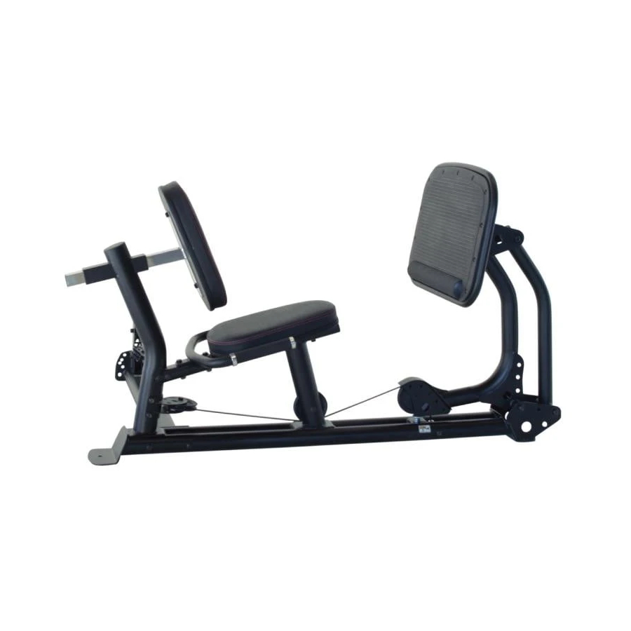
- Page 1 ASSEMBLY & OPERATION MANUAL LEG PRESS OPTION RECORD SERIAL NUMBER HERE www.inspirefitness.net by Health In Motion LLC Sept. 2006...
-
Page 2: Table Of Contents
TABLE OF CONTENTS Section Description………………………………………………….. Page Instructions………………………………………………………………….. Tools Requires……………………………………………………………… Parts & Hardware List………………………………………………….. Hardware Sizing Chart ………………………………………………… Assembly Instructions (M1 & M2)……………………………….. 4-10 Assembly Instructions (M3)………….…………………………….. 11-16 Decal Reference……………………………………………………………. Decal Placement…………………………………………………………… General Maintenance Information…….………………………… Maintenance Schedule…….………………………………………….. Limited Warranty.………………………….……………………………. -
Page 3: Instructions
Use only Inspire replacement parts on this machine. The use of any other brand of parts can also result in a loss of warranty. If you need help finding an authorized retailer, please contact us directly: Inspire Fitness 637 S. State College Blvd. Fullerton, CA 92831... -
Page 4: Parts & Hardware List
PARTS & HARDWARE LIST Item Parts Description Item Hardware Description Rec'd Rec'd Leg Press Base Bolt, 3/8-16 x 1" L Press Arm Bolt, 3/8-16 x 2" L Foot Plate Bolt, 3/8-16 x 2 1/4" L Handles Bolt, 3/8-16 x 2 1/2" L Attachment Arm Bolt, 3/8-16 x 3 3/4"... -
Page 5: Hardware Sizing Chart
HARDWARE SIZING CHART PAGE 3... -
Page 6: Assembly Instructions (M1 & M2)
ASSEMBLY INSTRUCTIONS PAGE 4... - Page 7 Assembly Procedure for Attaching Leg Press to M1 & M2 Go directly to page 11 if attaching Leg Press to M3 NOTE: The Leg Press may be attached to either side of the machine. The pictures show only one side Lower Cable Pulley 1 STEP 1...
- Page 8 Leg Press Base STEP 4 2 – 5” Hex Bolts STEP 5 4 – 3/8” Flat Washers 1 – 4 ¼” Hex Bolt 2 – 3/8” Lock Nuts 1 – 3/8” Flat Washer Press Arm Attachment Arm Pulley 1 STEP 2 1 –...
- Page 9 STEP 10 1 – Cable Adapter Floating Pulley Bracket Assembly Pulley 2 Pulley 3 STEP 8 STEP 7 1 – 3 ½” Pulley STEP 9 1 – 3 ½” Pulley 2 – 3 ¾” Hex Bolts 1 – 4 ¾” Hex Bolt 1 –...
- Page 10 Home Gym Lower Cable STEP 12 1 – 3 ½” Pulley 1 – 2” Hex Bolt 2 – 3/8” Flat Washers 1 – 3/8” Lock Nut Pulley 4 STEP 11 1 – 3 ½” Pulley 1 – 2” Hex Bolts 2 –...
-
Page 11: Cable Adjustment
STEP 15 Orthopedic Pad Seat Base Assembled Back & Seat Pad Step 15: Place Orthopedic Pad on Seat Base. Work the edge of pad into the groove of the Seat Base on all sides. Do not use sharp objects during installation. - Page 12 STEP 18 Back Pad Stem 2 – 1” Hex Bolts 2 – 3/8” Flat Washers STEP 17 2 – 2 ½” Hex Bolts 4 – 3/8” Flat Washers Back Pad 2 – 3/8” Lock Nuts Handles Seat Pad Leg Press Base Foot Plate STEP 20 STEP 19...
-
Page 13: Assembly Instructions (M3)
Assembly Procedure for Attaching Leg Press to M3 NOTE: The Leg Press may be attached to either side of the machine. The picture shows only one side. STEP 3 Disconnect Middle Cable Middle Cable STEP 2 Remove Pulley 1 & 1” Barrel Spacer From M3 Base Frame Pulley 1 &... - Page 14 STEP 7 5/16” Barrel Spacer STEP 8 2 – 5” Hex Bolts STEP 6 2 – 3/8” Lock Nuts 1 – 4 ¼” Hex Bolt 4 – 3/8” Flat Washers 1 – 3 ¾” Hex Bolt 1 – 3/8” Flat Washer 1 –...
- Page 15 STEP 13 1 – Cable Adapter Floating Pulley Bracket Assembly Press Arm Pulley 3 Pulley 4 STEP 11 STEP 10 1 – 3 ½” Pulley STEP 12 1 – 3 ½” Pulley 2 – 3 ¾” Hex Bolts 1 – 4 ¾” Hex Bolt 1 –...
- Page 16 Middle Cable Pulley 5 STEP 14 1 – 3 ½” Pulley 1 – 2” Hex Bolt 2 – 3/8” Flat Washers 1 – 3/8” Lock Nuts Pulley 6 STEP 15 STEP 17 STEP 16 1 – 3 ½” Pulley 1 – 2” Hex Bolt 1 –...
- Page 17 STEP 18 Orthopedic Pad Seat Base Assembled Back & Seat Pad Step 18: Place Orthopedic Pad on Seat Base. Work the edge of pad into the groove of the Seat Base on all sides. Do not use sharp objects during installation.
- Page 18 Back Pad Stem STEP 21 2 – 1” Hex Bolts 2 – 3/8” Flat Washers STEP 20 2 – 2 ½” Hex Bolts Back Pad 4 – 3/8” Flat Washers 2 – 3/8” Lock Nuts Handles Seat Pad Foot Plate Leg Press Base STEP 22 1 –...
-
Page 19: Decal Reference
DECAL REFERENCE PAGE 17... -
Page 20: Decal Placement
DECAL PLACEMENT Serial number label (60 x 40) “WARNING, PINCH POINTS” between press pedals, on leg press arm (60 x PAGE 18... -
Page 21: General Maintenance Information
GENERAL MAINTENANCE INFORMATION Warning: DO NOT place styrofoam or printed materials on the orthopedic seat pads. Over time, these may stick to the pads and mar the surface. Do not leave items sitting on the orthopedic seat pads, these pads have a special density that takes shape to objects and small objects will leave imprints in the surface that may take time to come out. -
Page 22: Maintenance Schedule
MAINTENANCE SCHEDULE HOME ROUTINE ENTRY DATE MAINTENANCE Inspect: Links, Pull Pins, WEEKLY Snap Links, Swivels, Weight Stack Pins WEEKLY Clean: Upholstery Inspect: Cables and WEEKLY their Fittings Inspect: Tautness of all WEEKLY Shrouds Inspect: Accessory Bars 3 MONTHS and Handles 3 MONTHS Inspect: All Decals Inspect: All Nuts and... -
Page 23: Limited Warranty
LIMITED WARRANTY In-Home Lifetime Warranty. This Warranty applies only in the United States to Inspire strength products manufactured or distributed by Health In Motion LLC. The warranty period to the original purchaser is lifetime of the original purchaser. Health In Motion warrants that the Product you have purchased for non-commercial, personal, family or household use from Health In Motion LLC or from an authorized Health In Motion reseller is free from defects in materials or workmanship under normal use during the warranty period.
Need help?
Do you have a question about the LEG PRESS OPTION and is the answer not in the manual?
Questions and answers