
Related Manuals for Inspire DUAL CHIN DIP


Summary of Contents for Inspire DUAL CHIN DIP
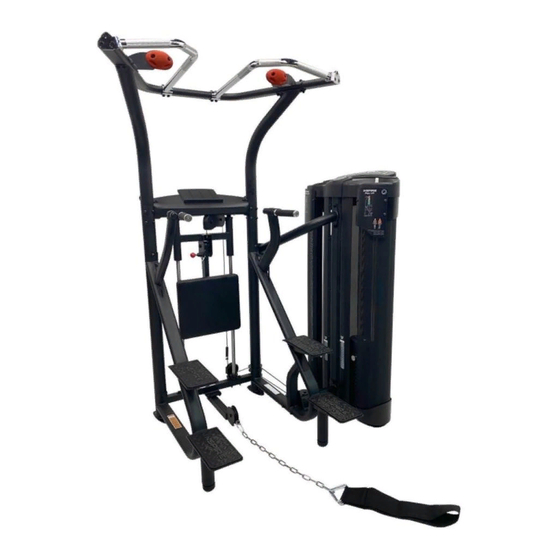
- Page 1 ASSEMBLY & OPERATION MANUAL DUAL CHIN DIP RECORD SERIAL NUMBER HERE www.inspirefitness.com by Health In Motion LLC 9-10-19...
- Page 2 CONGRATULATIONS… You’ve just taken the first step to a healthier and stronger body. This Dual Chin Dip machine by Inspire offers the key to unlocking your body’s potential. Regular strength training on a multi-gym has been shown to deliver a host of benefits including: increased muscle tone, decreased body fat, improved energy levels, a reduction in stress, and improved cardiac output.
-
Page 3: Table Of Contents
TABLE OF CONTENTS Section Description……………………………………………………. Page Important Safety Instructions………………………………………. Tools Required………………………………………………………………… Parts & Hardware List……………………………………………………. Cable Charts…………….……………………………………………………. Assembly Instructions……………………………………………………. Decal Reference……………………………………………………………… Decal Placement…………………………………………………………….. Training Tips…………………………………………………………………… General Maintenance Information…….…………………………… Maintenance Schedule…….……………………………………………… Limited Warranty…………………………………………………………….. -
Page 4: Important Safety Instructions
Operation Manual or the Exercise Book. Do not use attachments not recommended by the manufacturer. • Make sure bystanders are at least 5 feet away from the Dual Chin Dip machine while it is in use. • Keep children off the Dual Chin Dip machine at all times. -
Page 5: Parts & Hardware List
DUAL CHIN DIP PARTS & HARDWARE LIST Item Parts Description Qty Qty Rec'd Item Hardware Description Qty Qty Rec'd Main Frame M10 x 20 Hex Bolt Guide Cable Support M10 x 25 Hex Bolt Upright 1 M10 x 50 Hex Bolt... -
Page 6: Cable Charts
CHIN DIP CABLE CHART Connector Cable p/n GM887-500-003 1260 mm Assisted Cable p/n GM887-500-002 4030 mm Weighted Cable p/n GM887-500-001 4682 mm Cable lengths are in millimeters and for reference only. Cable lengths could change at any time without notice. Page 3... -
Page 7: Assembly Instructions
ASSEMBLY INSTRUCTIONS Page 4... - Page 8 Step 2 Step 1 4 - M10 x 75 Hex Bolts 8 - M10 Flat Washers 2 - M10 x 25 Hex Bolts 4 - M10 Locknuts 2 - M10 x 95 Hex Bolts 6 - M10 Flat Washers 2 - M10 Locknuts Guide Cable Support Upright 1...
- Page 9 Upright 1 Step 3 1 - M10 x 70 Hex Bolts 2 - M10 x 120 Hex Bolt Lower Attachment 6 - M10 Flat Washers 3 - M10 Locknuts Step 3: Attach the Lower Attachment Arm to Upright 1 using: 1 - M10 x 70 Hex Bolts 2–...
- Page 10 Base Frame Step 4 2 – M10 x 95 Button Head Bolts 2 – M10 x 95 Hex Bolts 8 – M10 Flat Washers 4 – M10 Locknuts 1 – M8 x 45 Button Head Bolts Left Leg 2 – M8 Washers 1 –...
- Page 11 Base Frame Step 5 2 – M10 x 100 Button Head Bolts Upper Attachment Arm 2 - M10 x 100 Hex Bolts 1 – M10 x 25 Hex Bolts Right Leg 9 - M10 Flat Washer 4 - M10 Locknuts 1 –...
- Page 12 Upper Attachment Step 6 2 - M10 x 70 Hex Bolts 3 - M10 x 100 Hex Bolts 10 - M10 Flat Washers 5 - M10 Locknuts Lower Attachment Adjustable Feet Step 6: Attach the Lower Attachment Arm and Upper Attachment Arm using: 2 - M10 x 70 Hex Bolts 3 - M10 x 100 Hex Bolts 10 - M10 Flat Washers 5 - M10 Locknuts...
- Page 13 Step 8 8 - M10 x 20 Hex Bolts Step 9 8 - M10 Flat Washers Linear Shaft Mount Knee Pad Slider Base Frame Linear Shaft Linear Shaft Mount Step 7: Carefully install the Linear Shafts into the Linear Bearings in the Knee Pad Slider. Attach the bottom Linear Shaft Mounts to the Shafts and tighten the set screws.
- Page 14 Step 10 Step 9 3 - M10 x 75 Hex Bolts 3 - M10 Flat Washers Knee Pad Support Step 9: Attach the Knee Pad to the Knee Pad Support using: 3 – M10 x 75 Hex Bolts 3 – M10 Flat Washers NOTE: Wrench Tighten Now.
- Page 15 Upper Arm Left Step 11 8 – M10 x 25 Button Head Bolts 8 – M10 Flat Washers 2 – M8 x 20 Button Head 4 – M8 Flat Washers 2 – M8 Locknuts Base Frame Step 11: Attach Upper Arm Left to the Base Frame using: 8 –...
- Page 16 Step 13 Upper Frame Climbing Grip Left 8 – M10 x 65 Hex Bolts 16 – M10 Flat Washers 8 – M10 Locknuts Climbing Grip Right Step 13: Attach the Upper Frame, Climbing Grip Left and Right to the 2 Upper Arms using: 8 –...
- Page 17 Upper Frame Step 14 4 - M10 x 25 Hex Bolts Left Upper Handle 3 - M10 x 25 Counter Sunk Bolts Right Upper Handle 5 - M10 Flat Washers 1 - M10 Locknuts Step 14: Attach the Left Upper Handle to the Upper Frame using: 3 –...
- Page 18 Step 16 4 - M10 x 25 Hex Bolts Base Frame 8 - M10 Washers 4 - M10 Locknuts Lower Pulley Arm Step 16: Attach the Lower Pulley Arm to the bottom of Base Frame using: 4 - M10 x 25 Hex Bolts 8 - M10 Flat Washers 4 - M10 Locknuts NOTE: Wrench Tighten Now.
- Page 19 Step 17 1- M4 x 60 Phillips Screw Plastic Cover 1 5- M4 x 15 Phillips Screw Step 18 5- M3 x 5 Phillips Screw Plastic Cover 2 Step 17: Attach Plastic Cover 1 to Base Frame using: 1- M4 x 60 Phillips Screw 5- M4 x 15 Phillips Screw NOTE: Do Not Over Tighten.
- Page 20 Step 19 2 - M10 x 90 Hex Bolts 1 - M10 x 75 Hex Bolt 6 - M10 Flat Washers 3 - M10 Locknuts 1 - M8 x 20 Hex Bolt 1 - M8 Flat Washer Upper Pulley Mount, Left Top Weight Stop Assembly Counter Balance...
- Page 21 Front of weight plate has recessed area for the number sticker Step 20 2 - M10 x 90 Hex Bolts 1 - M10 x 75 Hex Bolt 6 - M10 Flat Washers Bottom of weight 3 - M10 Locknuts plate has three feet 1 - M8 x 20 Hex Bolt 1 - M8 Flat Washer Upper Pulley...
- Page 22 Upper Pulley Upper Pulley Mount, Right Mount, Left Step 21 Upper Cable Routing Assisted Cable Weighted Cable Connector Cable p/n GM887-500-003 Assisted Cable GM887-500-002 Connector Cable p/n GM887-500-003 Weighted Cable GM887-500-001 Assisted Cable GM887-500-002 Step 21: Insert the Hex Bolt end of the Assisted Cable into the Top Weight Stack. Take the other end of the Assisted Cable, remove the slotted cable blot and guide it straight up through the Top Weight Stop and around both of the pulleys in the Upper Pulley Mount.
- Page 23 Knee Slider Step 23 Connector Cable 2 - M10 x 50 Hex Bolts Cable Adapter 4 – M10 Flat Washers 2 – M10 Locknuts Upper Main Cable Base Pulley Connector Inspect Hole “U” Bracket Assembly Main Frame Lower Main Base Pulley Lower Pulley Arm Assisted Cable Connector...
- Page 24 Step 24: Attach Rear Shroud Plate Support to Main Frame using: 1 – M8 x 100 Hex Bolt 2 – M8 Flat Washers 1 – M8 Locknut Optional: Insert M10 x 50 Fully Threaded Bolt from Step 28 to hold Rear Shroud Plate Support in place.
- Page 25 Step 25 Insert Shroud into Metal Pieces Upper Metal Shroud Fabric Shroud Lower Metal Shroud Step 25: To install Fabric Shroud, start from one end of the Lower Metal Shroud and insert the Fabric Shroud inwards as shown. Make sure to have the same orientation as shown or else the fabric shroud will be installed backwards.
- Page 26 Shroud Assembly Step 27 3 - M10 x 50 Fully Threaded Hex Bolts 3 - M10 Flat Washers Step 26 1 - M10 x 25 Button Head Bolt 2 - M10 x 70 Hex Bolts 3 - M10 Flat Washers Step 26: Attach the Lower Metal Shroud to the Upright 1 and Main Frame using: 1 –...
- Page 27 Step 28 5 – M6 x 12 Button Head Bolts 5 – M6 Flat Washers Left Shroud Plate Step 28: Attach Right Metal Shroud Plates to Upright 1 using: 5 – M6 x 12 Button Head Bolts 5 – M6 Flat Washers NOTE: Wrench Tighten Now.
- Page 28 Metal Shroud Placard Upper Metal Shroud Step 30: Attach the Metal Shroud Placard to the Upper Metal Shroud using: 3 – M8 x 12 Button Head Bolts 3 – M8 Flat Washers NOTE: Wrench Tighten Now. Step 31: Repeat step 30 for the other Upper Metal Shroud using: 3–...
- Page 29 Step 32 Rubber tablet holder only fits one Rubber Tablet Holder way. Make sure the outer edge of the tablet holder sits flat 1 - M8 x 12 Button Head Bolt against the molded cap. 1 - M8 Flat Washer 2 - M10 x 25 Button Head Bolts 2 - M10 Large OD Flat Washers Rubber Cup...
-
Page 30: Decal Reference
DECAL REFERENCE 877-738-1729 7,905,818; 8,096,929; 8,870,718; 9,067,100; 9,302,139 Page 27... - Page 31 DECAL REFERENCE Page 28...
-
Page 32: Decal Placement
DECAL PLACEMENT Globe Logo Label (85mm) Round Placard Label, Right “INSPIRE” logo “PINCH POINT “ Placard Label, Left Label (25 x 40) Chin Dip Weight Labels on right and left Metal Shroud Plates (40 x 180) Weight # labels “Patent” Label on (1 –... -
Page 33: Training Tips
Training Tips CONSULT A PHYSICIAN BEFORE STARTING ANY EXERCISE PROGRAM 1. Always warm up before you start weight training. This helps get your muscles warm and prevents injury. You can warm up with light cardio or by doing a light set of each exercise before going to heavier weights. -
Page 34: General Maintenance Information
GENERAL MAINTENANCE INFORMATION • Periodically inspect the cables for splitting, cracking or fraying. Also, watch for bulging or flat areas in the cable. • Immediately replace cables at the first signs of damage or wear. Never use equipment with damaged or worn cables. •... -
Page 35: Maintenance Schedule
MAINTENANCE SCHEDULE COMMERCIAL/ HOME ROUTINE ENTRY DATE LIGHT COMMERCIAL MAINTENANCE MAINTENANCE Inspect: Links, Pull Pins, Spring Clips, DAILY WEEKLY Swivels, Weight Stack Pins. DAILY WEEKLY Clean: Upholstery. Inspect: Cables and DAILY WEEKLY their Fittings for wear or looseness. Inspect: Tautness of DAILY WEEKLY all Shrouds. -
Page 36: Limited Warranty
This is the only express warranty applicable to Health In Motion’s “Inspire” branded strength products. Health In Motion neither assumes nor authorizes anyone to assume for it any other express warranty.
Need help?
Do you have a question about the DUAL CHIN DIP and is the answer not in the manual?
Questions and answers