Table of Contents
Advertisement
BEFORE YOU BEGIN
CONTENTS OF PACKAGING
LABEL PLACEMENT
ASSEMBLY INSTRUCTIONS
FINAL NOTES & FEATURES
COMPUTER OPERATION AND FUNCTION
PARTS LIST
EXPLODED DIAGRAMS
WARRANTY / DISCLAIMER
BEFORE YOU BEGIN
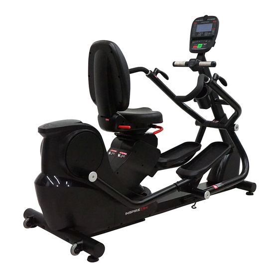
Thank you for selecting the INSPIRE CS4 CARDIOSTRIDER. For your safety and benefit, read
this manual carefully before using the machine. As a manufacturer, we are committed to
providing you complete customer satisfaction. If you have any questions, or find there are
missing or damaged parts, please call our TOLL-FREE customer service number. Our Customer
Service Agents will provide immediate assistance to you.
Table of Contents
HEALTH IN MOTION, LLC.
255 AIRPORT CIRCLE, SUITE
101
CORONA, CA 92880
Toll-Free Customer Service Number
1-877-738-1729
Mon. - Fri. 8 a.m. - 5 p.m. PST
www.inspirefitness.com
1
1
2
3
4
5
6 - 17
18 - 20
21 - 25
26 - 39
40 - 44
45 - 46
47 – 49
Advertisement
Table of Contents

Related Manuals for Inspire CS4


Summary of Contents for Inspire CS4
- Page 1 WARRANTY / DISCLAIMER BEFORE YOU BEGIN Thank you for selecting the INSPIRE CS4 CARDIOSTRIDER. For your safety and benefit, read this manual carefully before using the machine. As a manufacturer, we are committed to providing you complete customer satisfaction. If you have any questions, or find there are missing or damaged parts, please call our TOLL-FREE customer service number.
- Page 2 IMPORTANT SAFETY NOTICE PRECAUTIONS This exercise machine is built for optimum safety. However, certain precautions apply whenever you operate a piece of exercise equipment. Be sure to read the entire manual before you assemble or operate your machine. In particular, note the following safety precautions: •...
- Page 3 Packaging Contents...
- Page 4 Warning Labels...
- Page 5 Hardware Pack...
- Page 7 Step 1 Installing Rear Stabilizer Required Hardware: 2x (#155) Button Head Allen Screw (#156) Flat Head Allen Screw Required Parts: 1x (#19) Rear Stabilizer Installing Stabilizer A.) Locate the Rear Stabilizer mounting bracket on the back of the unit, near the power supply input. B.) The unit will have a black tube attached to the bracket.
- Page 9 Step 2 Installing Seat Pads Required Hardware: (#158) Button Head Allen Screw (#159) Spring Washer (#160) Flat Washer (#106) Allen Head Screw Required Parts: (#96) Seat Back Assembly 1x (#87) Seat Back Cover Installing Seat Back A.) Slide the bottom end of the (#96) Seat Back Assembly into the stem of the carriage. B.) Attach pieces together using: (#158) Button Head Allen Screw (#159) Spring Washer...
- Page 11 Step 3 Attaching the Mast Required Hardware: (#158) Button Head Allen Screw (#159) Spring Washer (#160) Flat Washer (#150) Phillip Screw Required Parts: (#2) Mast (#83) Front Cover Attaching the Mast A.) Position the bottom of the (#2) Mast at the upper opening of the main frame. B.) Connect the pair of cables inside the mast, to their respective cables out of the main frame.
- Page 13 Step 4 Attaching the Swing Arms Required Hardware: 2x (#167) Socket Cap Screw 2x (#46) Aluminum Cap 4x (#163) Button Head Allen Screw 4x (#135) Button Head Screw 4x (#164) Nut 4x (#162) Flat Washer 4x (#166) Flat Washer 4x (#154) Spring Washer Required Parts: (#4) Swing Arm Assembly, Left 1x (#5) Swing Arm Assembly, Right...
- Page 15 G.) Slide (#3) Heart Rate Grip/Bottle Holder Mount over the mounting post (D) on the upper part of the mast. Be sure to have the Inspire Logo on the upper side when mounting. H.) Center the handles so they are level and aligned with the console. Once centered; attach using:...
- Page 17 Step 6 Installing the Child Safety Lock Required Hardware: 4x (#106) Allen Head Screw Required Parts: (#30) Child Safety Lock Attaching the Child Safety Lock: A) The Child Safety Lock will be attached on the User RIGHT of the bottom rail. Locate the four preset threaded holes on the rail B) Be sure to align the Child Safety Lock with the cable and clip towards the front of the unit...
- Page 18 FINAL STEPS Calibrating the Adjustment Handle When you first receive your unit, the handles will be pre-calibrated to ensure a sturdy handle bar. If you ever find that the adjustment handle for your handle bars will not properly grip and/or lock down your handle bars in place;...
- Page 19 Note: In order to add tension to the grip mechanism, we must reset the handle at a more recessed angle, to allow more of the nut to tighten when pressed forward. Position the handle ¼ of a turn back, then set back on the grooves With the new set angle, press the handle to the fully pressed position.
- Page 20 Leveling the Unit Level the unit by unscrewing the leveling feet under the Rear Stabilizer and the front feet, so that both sit flat on the ground. Failure to do so, can cause damage to you and/or your unit. THE UNIT IS NOW COMPLETE...
- Page 21 FINAL NOTES & FEATURES Child Safety Lock ALWAYS engage the CHILD SAFETY LOCK ASSEMBLY after each use by clipping the hook onto the loop located UNDERNEATH the RIGHT PEDAL. Before each workout, disengage the hook from the loop, and clip onto the holding loop located on the mount itself.
- Page 22 SWIVEL SEAT Your CS4 is equipped with 180* swivel seat that allows you to swing out to the left and to the right. To enable the pivot, you must lift the handles located under your seat. This will disengage the lock.
- Page 23 ADJUSTABLE SEAT HEIGHT The CS4 is equipped with a motor powered seat that allows the user to adjust the height, with the touch of a button, while you are seated. Using the “UP” or “DOWN” arrows located on the left side of the console, the user can...
- Page 24 The unit can then save up to four different seat positions for quick recall. To save a specific height; use the “UP” and “DOWN” arrows to find a desired height. Then simply hold down one of the four Seat Position keys “1-4” for 2 seconds. The unit will make an audible beep, and the seat height is saved! NOTE: By default, the seat height adjustment will be LOCKED.
- Page 25 Polar T31Coded Included with your unit is a Polar heart rate monitor; Model T31. Technical specification Average 2500 hours Battery Life: Polyurethane Heart Rate Sensor Material: Polyurethane Strap material Buckle: Fabric: Nylon 46 % Polyester 32% Latex 22% Wearing the heart rate sensor 1) Fasten one end of the heart rate sensor to the elastic strap (Figure 1).
- Page 26 COMPUTER OPERATION AND FEATURES The CS4 Seated Cross Trainer is an exercise device with reciprocating leg and arm motion. The computer is operated through the keypad. Below is a description of each key function: A: QUICK START 1. Press at any time to restart a MANUAL workout. Time starts at 00:00 and counts up.
- Page 27 H: FOCUS KEY 1. Press to go to FOCUS WORKOUT selection 2. Press during any workout (except METS or HEART RATE) to convert current workout to FOCUS 3. Computer will start a TOTAL BODY FOCUS PROGRAM / MAX resistance Level 10 / workout time 15:00 I: SEAT POSITION UP/DOWN 1.
- Page 28 COMPUTER FUNCTION 3.1. QUICK START / MANUAL MODE: A: Press the “QUICK START” button. Resistance is manually changed. Time counts up from 00:00 B: Press STOP/RESET to pause the program. TIME will stop running. C: Press STOP/RESET again to reset computer (computer does not need to reboot, just start from Normal Mode).
- Page 29 • Press the UP or DOWN key to scroll through 36 alpha-numeric characters (first 26 letters A-Z, then 10 numbers 0-9) and 1 blank space. • After 1 letter is set, the white box is blinking and is empty • Press the ENTER key to accept alpha-numeric character and move to next space.
- Page 30 • The position shown ‘x’ is the current position of seat • Press SEAT UP/DOWN to move the seat to the desired position • Press ENTER to save SEAT POSITION and go to GENDER SELECTION • Press STOP/RESET to go back to USER SELECTION •...
- Page 31 • Press UP/DOWN to adjust WEIGHT value in 1 lb. increments (NOTE: If computer is set to METRIC, WEIGHT is adjusted in 1 kg. increments. • Press and hold the UP/DOWN key for 1 second and the WEIGHT value increments by 10 lbs/second (or 5 kg/second). •...
- Page 32 Press the UP or DOWN key to toggle between NO and YES. Press ENTER on YES to reset data to 0. Press ENTER or STOP/RESET on NO to cancel data reset and go back to USER SETTINGS. 3.3. PROGRAMS: Press the PROGRAMS key. DOT MATRIX displays “PROFILE”.
- Page 33 • Press QUICK START to BEGIN WORKOUT using WORKOUT TIME of 15:00 WORKOUT TIME • DOT MATRIX reads “WORKOUT TIME 15:00”. ‘15:00’ is highlighted • Press the UP or DOWN key to adjust WORKOUT TIME in 1 minute increments (up to a maximum of 99:00 minutes). •...
- Page 34 HEART RATE COOLDOWN: • All Heart Rate Control programs include a 5:00 minute cool down period that begins after the program has ended. • RESISTANCE is set to Level 1 • After completing a workout DOT MATRIX will read WORKOUT COMPLETE and computer will beep a long beep.
- Page 35 2. WORKOUT SETTINGS (TARGET) ENTER TARGET HEART RATE: • DOT MATRIX reads "TARGET HR 100" • Press the UP and DOWN key to change the TARGET value increments of 1 -year • Press ENTER to accept TARGET and move to WORKOUT TIME. •...
- Page 36 • Press UP/DOWN key to toggle • Press ENTER to select a focus workout and go to MAXIMUM RESISTANCE LEVEL. • Press QUICK START to begin workout using default settings (level 7, 15:00) • Press STOP/RESET to go back to PROGRAM SELECTION MAXIMUM RESISTANCE LEVEL •...
- Page 37 FOCUS WORKOUT DETAILS: • Program runs through 8 time segments per cycle to focus on training certain areas of body • For workouts less than 10:00 minutes, programs runs 1 cycle (8 total time segments) • For workouts between 10:00 minutes and 19:59 minutes, programs runs 2 cycles (16 total time segments) •...
- Page 38 TOTAL BODY FOCUS CYCLE RESISTANCE HANDLE FOOT SEGMENT INSTRUCTION SETTING POSITION (A) POSITION (B) .5*MAX PEDALS PUSH ARMS AND LEGS PEDALS PUSH ARMS AND LEGS .5 * MAX PEGS PUSH WITH ARMS .5*MAX PEGS PULL WITH ARMS .75*MAX DOWN PEDALS PALMS UP / BICEPS DOWN PEDALS...
- Page 39 4. VIEWS Press the VIEW button to toggle through available LCD screen layouts (STANDARD, BASIC, HEART RATE, CALORIES, FOCUS) The LCD will display the VIEW name for 1 second then switch to the selected view.
- Page 40 CS4 PARTS LIST YL ERP Code Quantity Part Name 195A100*0H0R000 Frame Assembly 195A200*0H0R000 Console Mast 195AQ00*P0QR000 Heart Rate Handlebar 195A400*0H0R000 Swing Arm Assembly( L ) 195A500*0H0R000 Swing Arm Assembly ( R ) 195A700*0H0R000 Pedal Tube Assembly ( L ) 195A600*0H0R000...
- Page 41 195AI18*AB0R000 Locking Block 195ES23*P0QR000 Tension Nut, Right 195AI30*BH0R000 Adjustment Handle 195AI29*B00R000 Aluminum Deco Ring 553A107*A000000 Snap Hook 195ES25*P0QR000 Tension Nut, Left 195AI09*AA0R000 Bearing Support Tube I 195AI06*B00R000 Aluminum Cap 195AI17*AA0R000 Bearing Support Tube II 195AI07*B00R000 Aluminum End Cap II 195AI45*AA0R000 Bearing Locking Plate 195AI17*AA0R000 Bearing Support Tube III...
- Page 42 195ES21*P0QR000 Pedal Cover 195ES13*P0QR000 Front Shroud ( L ) 195ES12*P0QR000 Front Shroud ( R ) 195ES14*P0QR000 Rubber Strip 195ES17*P0QR000 Front Cover 195ES19*P0QR000 Bottle Holder 195ES08*P0QR000 Seat Back Tilt Cover ( L ) 195ES09*P0QR000 Seat Back Tilt Cover ( R ) 195ES18*P0QR000 Seat Back Cover 195ES16*P0QR000...
- Page 43 752A128*AA0R001 Tension Spacer MM05008*RFFDS0Q Phillips Flat Head Screw M5*8 MM12020*RFF0G0Q Hex Screw M12*20 MT12000*RA00001 Spring Washer D12 MP12220*RF02001 Flat Washer D12.5*D22*T2.0 MM08000*RFH0000 Nylon Nut M8 MM10000*RFH0000 Nylon Nut M10 MT10000*RF00001 Spring Washer D10 MP10200*RF20001 Flat Washer D10.5*D25*T2.0 MM06015*R0FCS0Q Phillips Head Screw M6*15 MB17000*RC00000 Wave Washer D17.2*D22*T0.3 MK08000*RC00000...
- Page 44 MP06130*RD12001 Flat Washer D6.5*D13*T1.5 MM04012*R0FDS0Q Phillips Screw M4*12 MP08160*R015001 Flat Washer D8.5*D16*T1.5 MM10068*R0FZN0B Button Head Allen Screw M10*68 MM10000*R0H0000 Nut M10 MM08015*RFA0N2Q Flat Head Allen Screw M8*15 MP10200*R020001 Flat Washer D10.5*D20*T2.0 MM10025*R0FCN0Q Socket Cap Screw M10*15 422E006*P00R000 Zip Tie 280A001*000R002 Magnet 195E004*000R000 Console...
- Page 45 EXP 1...
- Page 46 EXP 2...
- Page 47 Service procedures To obtain warranty parts, you must return the parts to Inspire Fitness or an authorized Inspire Fitness retailer in its original container (or equivalent). You must pre-pay any shipping charges, taxes, or any other charges associated with transportation of the product.
- Page 48 (a) as a result of accident, misuse, or abuse; (b) by the use of parts not manufactured or sold by Inspire Fitness; (c) by modification of the product;...
- Page 49 This warranty gives you specific legal rights and you may also have other rights that may vary from state to state. This is the only express warranty applicable to Inspire Fitness’ “Inspire” branded cardio products. Inspire Fitness neither assumes nor authorizes anyone to assume for it any other express warranty.
Need help?
Do you have a question about the CS4 and is the answer not in the manual?
Questions and answers