
Related Manuals for Inspire FPC1C


Summary of Contents for Inspire FPC1C
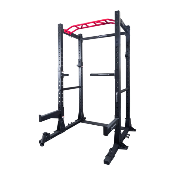
- Page 1 Model # FPC1C USER MANUAL FULL POWER CAGE by Health in Motion LLC October 2020 Record Serial Number Here...
-
Page 2: Table Of Contents
BEFORE YOU BEGIN Thank you for selecting the Inspire Fitness FPC1C. For your safety and benefit, read this manual carefully before using the machine. As a manufacturer, we are committed to providing you complete customer satisfaction. If you have any questions, or find there are missing or damaged parts, please call our TOLL-FREE customer service number. -
Page 3: Important Safety Notice
IMPORTANT SAFETY NOTICE PRECAUTIONS This exercise machine is built for optimum safety. However, certain precautions apply whenever you operate a piece of exercise equipment. Be sure to read the entire manual before you assemble or operate your machine. Please note the following safety precautions: Always keep children and pets away from the machine. -
Page 4: Exploded View
EXPLODED VIEW Pg. 4 V1.0... -
Page 5: Components List
COMPONENTS LIST X 10 Pg. 5 V1.0... -
Page 6: Hardware Pack
HARDWARE PACK Pg. 6 V1.0... - Page 7 STEP 1 BOTTOM BASE FRAME ASSEMBLY Refer to the illustration above for location and orientation of components. This step consists of a left side and a right side. • Fasten with Bolt (28), Washer (36), and Locknut (35). Connect Bottom Foot Plate (15) to Bottom Base Frame (1), Bottom Inner Plate (13), and the Bottom Cross Brace (14), place these items towards the one end of the bottom base frame.
- Page 8 STEP 2 UPRIGHT BEAM AND REAR CROSS BAR INSTALLATION Refer to the illustration above for location and orientation of components. • Fasten with Bolt (28), at the bottom, Bolt (29) above, Washer (36), and Lock Nut (35). Connect Upright Beam (5) to the Bottom Base Frame Assembly.
- Page 9 STEP 3 UPRIGHT BEAMS FRONT INSTALLATION Refer to the illustration above for location and orientation of components. Fasten with Bolt (29) at the bottom, Washer (36), and Lock Nut (35). Connect Upright Beam (5) to the Bottom Base • Frame Assembly. Left side and Right side. •...
- Page 10 STEP 4 UPPER CROSS BARS INSTALLATION Refer to the illustration above for location and orientation of components. • Fasten with Bolt (29), Washer (37), Washer (36), and Lock Nut (35). • Connect the Upper Cross Bar (2), to the 2 the Upright Beams. Left side and Right side. •...
- Page 11 STEP 5 MONKEY BAR INSTALLATION Refer to the illustration above for location and orientation of components. • Fasten with Bolt (31), Washer (36), and Lock Nut (35). Connect the Monkey Bar (4), to the Upper Cross Bars (2), and Deco Plate (23). Left side and Right side. •...
- Page 12 STEP 6 RESISTANCE BAND PEGS, LANDMINE, AND BATTLE ROPE ATTACHMENT INSTALLATION Refer to the illustration above for location and orientation of components. RESISTANCE BAND PEGS (4 Places): one at top, and one at bottom on each side. • Fasten with Bolt (30), Washer (36), and Lock Nut (35). •...
- Page 13 STEP 7 HOOKS, PARALLEL BARS, AND SAFETY TUBES ATTACHMENT Before beginning a workout, make sure all the safety tubes are in place. Locate a desired height to place the Safety Bar (12) thru the hole of the beam and the Safety Bar Sleeve (40). PROCEED TO INSTALL IN PLACE: •...
-
Page 14: Step 1
ATTACHMENTS INSTALLATION J-Cups (6), (7) Step 1 Step 2 Step 3 Parallel bars (10), (11) Step 1 Step 2 Step 3 Safety Catches (8), (9) Step 1 Step 2 Step 3 Pg. 14 V1.0... - Page 15 PARTS LIST Name Description Qty. Bottom Base Frame L/R FPC1-01 Upper Cross Bar FPC1-02 Rear Cross Bar FPC1-03 Monkey Bar FPC1-04 Upright Beam FPC1-05 Left J Cup FPC1-06 Right J Cup FPC1-07 Left Safety Catch FPC1-08 Right Safety Catch FPC1-09 Left Parallel Bars FPC1-10 Right Parallel Bars...
- Page 16 This is the only express warranty applicable to Health In Motion’s “Inspire” branded strength products. Health In Motion neither assumes nor authorizes anyone to assume for it any other express warranty.
- Page 17 Modèle FPC1C MANUEL D’UTILISATION SUPPORT À USAGE MULTIPLE COMPLET Health in Motion LLC octobre 2020 Inscrire le numéro de série ici...
-
Page 18: Avant De Commencer
Pour enregistrer le produit aux fins de garantie, visiter le inspirefitness.com/support. AVANT DE COMMENCER Merci d’avoir choisi le support Inspire Fitness FPC1C. Par mesure de sécurité et pour optimiser l’utilisation, prière de lire attentivement le présent manuel avant d’utiliser l’appareil. En tant que fabricant, nous mettons tout en œuvre pour assurer l’entière satisfaction de notre clientèle. -
Page 19: Avis De Sécurité Important
AVIS DE SÉCURITÉ IMPORTANT CONSIGNES DE SÉCURITÉ Cet appareil est conçu pour assurer une sécurité optimale. Son utilisation exige toutefois certaines précautions. Bien lire l’intégralité du manuel avant de monter ou d’utiliser l’appareil et prendre note des consignes de sécurité suivantes : Toujours garder l’appareil hors de la portée des enfants et des animaux domestiques. -
Page 20: Vue Éclatée
VUE ÉCLATÉE Pg. 4 V1.0... -
Page 21: Tableau Des Composants
TABLEAU DES COMPOSANTS X 10 Pg. 5 V1.0... -
Page 22: Ensemble De Quincaillerie
ENSEMBLE DE QUINCAILLERIE 28 M12 x 110 mm (6) 29 M12 x 105 mm (26) 30 M12 x 100 mm (4) 31 M12 x 80 mm (4) 32 M12 x 75 mm (4) 41 (2) 36 Ø13 x Ø24 x 2,5 (76) 37 Ø13 x Ø37 x 3 (12) 35 M12 (44) Pg. -
Page 23: Étape 1
28 M12 x 110 (4) 29 M12 x 105 (4) 35 M12 (8) 41 (2) 36 Ø13 x Ø24 x 2,5 (16) ÉTAPE 1 MONTAGE DE LA BASE Voir l’illustration ci-dessus pour connaitre l’emplacement et l’orientation des pièces. Cette étape se divise en deux parties, le côté... -
Page 24: Étape 2
28 M12 x 110 (2) 29 M12 x 105 (6) 35 M12 (8) 36 Ø13 x Ø24 x 2,5 (12) 37 Ø13 x Ø37 x 3 (4) 41 (2) ÉTAPE 2 INSTALLATION DES MONTANTS ET DE LA TRAVERSE ARRIÈRE Voir l’illustration ci-dessus pour connaitre l’emplacement et l’orientation des pièces. •... -
Page 25: Étape 3
29 M12 x 105 (4) 35 M12 (4) 36 Ø13 x Ø24 x 2,5 (8) 41 (2) ÉTAPE 3 INSTALLATION DES MONTANTS AVANT Voir l’illustration ci-dessus pour connaitre l’emplacement et l’orientation des pièces. À l’ a ide de boulons (29), de rondelles (36) et d’écrous de blocage (35), relier les montants (5) à la base, à gauche et à droite. •... -
Page 26: Étape 4
29 M12 x 105 (8) 35 M12 (8) 36 Ø13 x Ø24 x 2,5 (8) 37 Ø13 x Ø37 x 3 (8) 41 (2) ÉTAPE 4 INSTALLATION DES TRAVERSES SUPÉRIEURES Voir l’illustration ci-dessus pour connaitre l’emplacement et l’orientation des pièces. •... -
Page 27: Étape 5
31 M12 x 80 (4) 35 M12 (4) 36 Ø13 x Ø24 x 2,5 (8) 41 (2) ÉTAPE 5 INSTALLATION DES BARRES DE SUSPENSION Voir l’illustration ci-dessus pour connaitre l’emplacement et l’orientation des pièces. • Utiliser des boulons (31), des rondelles (36) et des écrous de blocage (35). Relier les barres de suspension (4) aux traverses supérieures (2) et aux plaques décoratives (23), à... -
Page 28: Étape 6
29 M12 x 105 (4) 30 M12 x 100 (4) 32 M12 x 75 (4) 35 M12 (12) 36 Ø13 x Ø24 x 2,5 (24) 41 (2) ÉTAPE 6 INSTALLATION DES CHEVILLES POUR BANDES ÉLASTIQUES, DU MANCHON PIVOTANT ET DE L’ANCRAGE POUR CORDES ONDULATOIRES Voir l’illustration ci-dessus pour connaitre l’emplacement et l’orientation des pièces. -
Page 29: Étape 7
ÉTAPE 7 INSTALLATION DES CROCHETS, DES BARRES PARALLÈLES ET DES BARRES DE SÉCURITÉ Avant tout entrainement, s’assurer que les barres de sécurité sont en place. Insérer une tige de sureté (12) à la hauteur désirée dans l’un des orifices du montant et dans le manchon (40). INSTALLER: •... -
Page 30: Installation Des Accessoires
INSTALLATION DES ACCESSOIRES Crochets en J (6) et (7) Étape 1 Étape 2 Étape 3 Barres parallèles (10) et (11) Étape 1 Étape 2 Étape 3 Barres de sécurité (8) et (9) Étape 1 Étape 2 Étape 3 Pg. 14 V1.0... - Page 31 PARTS LIST Description té Traverse de la base, gauche et droite FPC1-01 Traverse supérieure FPC1-02 Traverse arrière FPC1-03 Barres de suspension FPC1-04 Montant FPC1-05 Crochet en J, gauche FPC1-06 Crochet en J, droite FPC1-07 Barre de sécurité, gauche FPC1-08 Barre de sécurité, droite FPC1-09 Barre parallèle, gauche FPC1-10...
-
Page 32: Garantie / Avis De Non-Responsabilité
Cette garantie est la seule garantie explicite s’appliquant aux produits de musculation de marque Inspire de Health In Motion. Health In Motion ne reconnait aucune autre garantie explicite et n’autorise personne d’autre à... - Page 33 Modelo N.º FPC1C MANUAL DEL USUARIO JAULA DE POTENCIA COMPLETA Por Health In Motion LLC Agosto de 2020 Registre el número de serie aquí...
- Page 34 Para registrar su producto para la garantía, visite inspirefitness.com/support. ANTES DE COMENZAR Gracias por elegir el Inspire Fitness FPC1. Por su seguridad y beneficio, lea este manual con atención antes de usar la máquina. Como fabricantes, nos comprometemos a proporcionarle una satisfacción completa como cliente. Si tiene alguna pregunta, o si faltan partes o están dañadas, llame a nuestro número GRATUITO de servicio al cliente.
-
Page 35: Antes De Comenzar
AVISO IMPORTANTE DE SEGURIDAD PRECAUCIONES Esta máquina de ejercicio ha sido diseñada para ofrecer seguridad óptima. Sin embargo, se deben tomar ciertas precauciones al operar un equipo de ejercicio. Asegúrese de leer todo el manual antes de montar o usar su máquina. Tenga en cuenta las siguientes precauciones de seguridad: Siempre mantenga a los niños y las mascotas alejados de la máquina. -
Page 36: Vista De Despiece
VISTA DE DESPIECE Pg. 4 V1.0... -
Page 37: Lista De Componentes
LISTA DE COMPONENTES X 10 Pg. 5 V1.0... -
Page 38: Paquete De Materiales
PAQUETE DE MATERIALES N.º 28 M12 x 110 mm (6) N.º 29 M12 x 105 mm (26) N.º 30 M12 x 100 mm (4) N.º 31 M12 x 80 mm (4) N.º 32 M12 x 75 mm (4) N.º 41 (2) N.º... -
Page 39: Paso 1
N.º 28 M12 x 110 (4) N.º 29 M12 x 105 (4) N.º 35 M12 (8) N.º 41 (2) N.º 36 Ø13 x Ø24 x 2,5 (16) PASO 1 MONTAJE DE LA ESTRUCTURA DE LA BASE Consulte la ilustración anterior para ver la ubicación y orientación de los componentes. Este paso consta de un lado izquierdo y un lado derecho. -
Page 40: Paso 2
N.º 28 M12 x 110 (2) N.º 29 M12 x 105 (6) N.º 35 M12 (8) N.º 36 Ø13 x Ø24 x 2,5 (12) N.º 37 Ø13 x Ø37 x 3 (4) N.º 41 (2) PASO 2 INSTALACIÓN DE LAS VIGAS VERTICALES Y DE LA BARRA CRUZADA TRASERA Consulte la ilustración anterior para ver la ubicación y orientación de los componentes. -
Page 41: Paso 3
N.º 29 M12 x 105 (4) N.º 35 M12 (4) N.º 36 Ø13 x Ø24 x 2,5 (8) N.º 41 (2) PASO 3 INSTALACIÓN DE LAS VIGAS VERTICALES DELANTERAS Consulte la ilustración anterior para ver la ubicación y orientación de los componentes. Use pernos (29), arandelas (36) y tuercas de fijación (35) para conectar las vigas verticales (5) a la estructura de •... -
Page 42: Paso 4
N.º 29 M12 x 105 (8) N.º 35 M12 (8) N.º 36 Ø13 x Ø24 x 2,5 (8) N.º 37 Ø13 x Ø37 x 3 (8) N.º 41 (2) PASO 4 INSTALACIÓN DE LAS BARRAS CRUZADAS SUPERIORES Consulte la ilustración anterior para ver la ubicación y orientación de los componentes. •... -
Page 43: Paso 5
N.º 31 M12 x 80 (4) N.º 35 M12 (4) N.º 36 Ø13 x Ø24 x 2,5 (8) N.º 41 (2) PASO 5 INSTALACIÓN DE LA BARRA TREPADORA Consulte la ilustración anterior para ver la ubicación y orientación de los componentes. •... - Page 44 N.º 29 M12 x 105 (4) N.º 30 M12 x 100 (4) N.º 32 M12 x 75 (4) N.º 35 M12 (12) N.º 36 Ø13 x Ø24 x 2,5 (24) N.º 41 (2) ÉTAPE 6 INSTALACIÓN DE LAS CLAVIJAS DE LA BANDA DE RESISTENCIA, LA BARRA LANDMINE Y LA CONEXIÓN DE LA SOGA DE ENTRENAMIENTO Consulte la ilustración anterior para ver la ubicación y orientación de los componentes.
-
Page 45: Paso 6
PASO 7 GANCHOS, BARRAS PARALELAS Y CONEXIÓN DE LOS TUBOS DE SEGURIDAD Antes de comenzar un entrenamiento, asegúrese de que todos los tubos de seguridad estén colocados. Ubique una altura deseada para colocar la barra de seguridad (12) a través del orificio de la viga y la manga de la barra de seguridad (40). INSTALLER: •... -
Page 46: Paso 7
INSTALACIÓN DE ACCESORIOS Soportes en J (6) y (7) Paso 1 Paso 2 Paso 3 Barras paralelas (10) y (11) Paso 1 Paso 2 Paso 3 Soportes de seguridad (8) y (9) Paso 1 Paso 2 Paso 3 Pg. 14 V1.0... - Page 47 LISTA DE PIEZAS Descripción Cant. Estructura de la base, izquierda y derecha FPC1-01 Barra cruzada superior FPC1-02 Barra cruzada trasera FPC1-03 Barra trepadora FPC1-04 Viga vertical FPC1-05 Soporte en J izquierdo FPC1-06 Soporte en J derecho FPC1-07 Soporte de seguridad izquierdo FPC1-08 Soporte de seguridad derecho FPC1-09...
-
Page 48: Garantía / Exención De Responsabilidad
(o por país o por provincia). Esta es la única garantía explícita de aplicación a los productos de entrenamiento de la marca «Inspire» de Health In Motion. Health In Motion no asume ni autoriza a ninguna persona a asumir en su nombre ninguna otra garantía expresa. - Page 49 モデル #FPC1C ユーザーマニュアル フルパワー ケージ Health In Motion LLC 2020 年 8 月 ここにシリアルナンバーを記録して ください。...
- Page 50 手順 2............................8 手順 3............................9 手順 4............................10 手順 5............................11 手順 6............................12 手順 7............................13 付属品の設置..........................14 部品リス ト/製品データ......................15 保証/免責事項..........................16 はじめに Inspire FitnessのFPC1をお買い上げいただきありがとうございます。 お客様の安全と利益を守るために、 本製品マシーンをご使用 になる前にこのマニュアルをよ くお読みください。 当社は、 製造者として最高の顧客満足度を提供できるよう尽力しています。 ご質 問、 部品の欠品、 損傷等がありましたら、 カスタマーサービスフリーダイヤルへご連絡ください。 当社のカスタマーサービス代行業者 が直ちにサポートさせていただきます。 Eメール 電話 チャット costcosupport@inspirefitness.com 877-738-1729 www.inspirefitness.com 2 ページ...
- Page 51 重要安全事項 注意 このエクササイズマシーン機器には、 最高の安全性が組み込まれています。 しかしながら、 どのエクササイズ機器を操作する際もは、 常にある程度の注意が必要です。 マシーン機器の組み立て、 操作する前に必ず本マニュアルをすべてお読みください。 また、 次の安 全事項にご注意ください。 1. お子様やペッ トをマシーン機器に近づかせないでください。 マシーン機器と同じ部屋にいるお子様から決して目を離さないでく ださい。 不適切な使用により、 マシーン機器の連動部によ って重大な傷害や死亡事故が起こるおそれがあります。 2. 連動部間の連結部分に手や足を置かないでください。 傷害の原因となり、 機器に損傷を与えるおそれがあります。 使用中は、 お 子様を作動中の連結部の近くへ行かせたり近づかせたりしないでください。 3. 使用者にめまい、 吐き気、 胸の痛み、 その他の異常な症状が出た場合は、 すぐにトレーニングを止め、 直ちに医師に相談して くだ さい。 4. マシーン機器は開放的で水平な面に設置して ください。 5. マシーン機器を屋外または水の近く で使用しないでください。 6. すべての可動部に手を触れないでください。...
- Page 52 分解立体図 4 ページ V1.0...
- Page 53 部品リスト X 10 5 ページ V1.0...
- Page 54 取付金具 #28 M12 × 110mm 6個 #29 M12 × 105mm 26個 #30 M12 × 100mm 4個 #31 M12 × 80mm 4個 #32 M12 × 75mm 4個 #41 2個 #36 φ13 ×φ24 × 2.5 76個 #37 φ13 × φ37× 3 12個 #35 M12 44個 6 ページ V1.0...
- Page 55 #28 M12 × 110 4個 #29 M12 × 105 4個 #35 M12 8個 #41 2個 #36 φ13 × φ24 × 2.5 16 手順 1 下部ベースフレームの組立 部品の位置と向きは上図を参照して ください。 このステップは、 左側と右側で構成されます。 • ボルト (28) と座金 (36) 、 ロックナッ ト (35) で締めて く ださい。 下部フッ トプレート (15) を下部ベースフレーム (1) 、 下部インナープレ ート...
- Page 56 #28 M12 ×110 2個 #29 M12 × 105 6個 #35 M12 8個 #36 φ13 × φ24 × 2.5 12個 #37 φ13 × φ37 × 3 4個 #41 2個 手順 2 直立ビームと後部クロスバーの設置 部品の位置と向きは上図を参照して ください。 • ボルト (28) ( 下部) 、 ボルト (29) ( 上部) 、 座金 (36) 、 ロックナット (35) で締めて ください。 直立ビーム (5) を下部ベースフレーム組 立部品に接続します。...
- Page 57 #29 M12 × 105 4個 #35 M12 4個 #36 φ13 × φ24 × 2.5 8個 #41 2個 手順 3 直立ビーム前部の設置 部品の位置と向きは上図を参照して ください。 • ボルト (29) ( 下部) 、 座金 (36) 、 ロックナット (35) で締めて ください。 直立ビーム (5) を下部ベースフレーム組立部品に接続しま す。 左側と右側があります。 •...
- Page 58 #29 M12 × 105 8個 #35 M12 8個 #36 φ13 × φ24 ×2.5 8個 #37 φ13 × φ37 × 3 8個 #41 2個 手順 4 上部クロスバーの設置 部品の位置と向きは上図を参照して ください。 • ボルト (29) 、 座金 (37) 、 座金 (36) 、 ロックナット (35) で締めて ください。 •...
- Page 59 #31 M12 × 80 4個 #35 M12 4個 #36 φ13 × φ24 × 2.5 8 #41 2個 手順 5 モンキーバーの設置 部品の位置と向きは上図を参照して ください。 • ボルト (31) 、 座金 (36) 、 ロックナット (35) で締めて ください • モンキーバー (4) を上部クロスバー (2) 、 デコプレート (23) に接続します。 左側と右側があります。 11 ページ...
- Page 60 #29 M12 ×105 4個 #30 M12 × 100 4個 #32 M12 × 75 4個 #35 M12 12個 #36 φ13 × φ24 × 2.5 24個 #41 2個 手順 6 抵抗バンドペグ、 ランドマイン、 バトルロープ付属品接続ループの設置 部品の位置と向きは上図を参照して ください。 抵抗バンドペグ (4箇所) : 両側の上部に 1個、 下部に 1個 •...
- Page 61 手順 7 フック、 平行バー、 安全チューブの取付 トレーニングを始める前に、 すべての安全チューブが正しい位置にあることを確認して ください。 お好みの高さのビーム穴に 安全バー (12) を通し、 安全バースリーブ (40) を取り付けて ください。 正しい位置に設置して ください。 • 平行バー (10) 、 ( 11) • Jカップ (6) 、 ( 7) • 安全キャ ッチ (8) 、 ( 9) (付属品は次ページの図を参照して ください。 ) 13 ページ...
- Page 62 付属品の設置 Jカップ (6) 、 ( 7) 手順 1 手順 2 手順 3 平行バー (10) 、 ( 11) 手順 1 手順 2 手順 3 安全キャッチ (8) 、 ( 9) 手順 1 手順 2 手順 3 14 ページ V1.0...
- Page 63 部品リスト 番号 名称 説明 数量 下部ベースフレーム 左/右 FPC1-01 上部クロスバー FPC1-02 後部クロスバー FPC1-03 モンキーバー FPC1-04 直立ビーム FPC1-05 Jカップ 左 FPC1-06 Jカップ 右 FPC1-07 安全キャ ッチ 左 FPC1-08 安全キャ ッチ 右 FPC1-09 平行バー 左 FPC1-10 平行バー 右 FPC1-11 安全バー FPC1-12 下部インナープレート FPC1-13 下部クロスブレース...
- Page 64 の条件に限定されます。 Health In Motionまたはいずれの関連業者も、 事故または必然の損傷に対する責任を負わないものとします。 Health In Motionは、 Health In Motionが製造日以降、 改造、 無視、 乱用、 誤用、 通常の使用による摩耗、 事故、 移動中または設置中の損傷、 火事、 洪水、 または天災によると判断した部品の修理または 交換に責任を負いません。 黙示保証期間の制限、 事故または必然の損傷の例外または制限を認めていない州もあります。 したがって、 上記の制限または例外がお客様に 当てはまるとは限りません。 この保証書は、 購入者に明確な法的権利を与えます。 また、 州ごとに異なるその他の権利がある場合があります。 本書は、 Health In Motionの 「Inspire」 ブランドの耐久製品を対象とした唯一の明示の担保です。 Health in Motionは、 その他の明示の担保を受ける権利をいかなる者にも与えず、 認めません 16 ページ V1.0...
- Page 65 V1.0...
Need help?
Do you have a question about the FPC1C and is the answer not in the manual?
Questions and answers