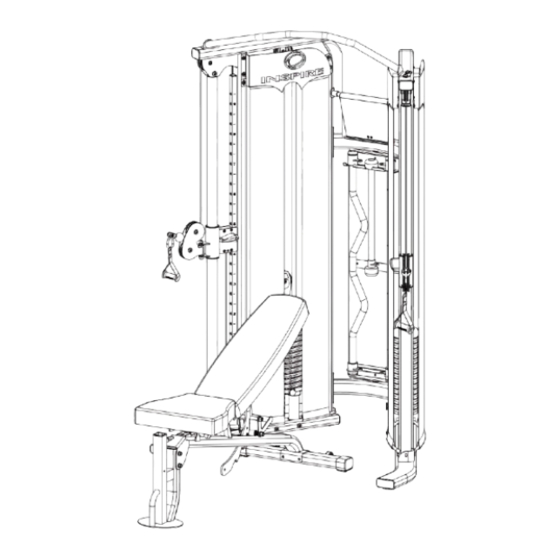
Inspire FT1 Assembly & Operation Manual
Hide thumbs
Also See for FT1:
- Assembly & operation manual (22 pages) ,
- Assembly & operation manual (13 pages)

Related Manuals for Inspire FT1


Summary of Contents for Inspire FT1
- Page 1 ASSEMBLY & OPERATION MANUAL RECORD SERIAL NUMBER HERE www.inspirefitness.net by Health In Motion LLC June 2011...
-
Page 2: Table Of Contents
Use the parts list included in this manual to verify that all parts are accounted for before assembly. If any parts are missing, contact the retailer of this home gym for replacement parts. Or, call Inspire at 714-738-1729 Service of your home gym should only be performed by an authorized INSPIRE retailer. -
Page 3: Important Safety Notices
IMPORTANT SAFETY NOTICE PRECAUTIONS This exercise machine is built for optimum safety. However, certain precautions apply whenever you operate a piece of exercise equipment. Be sure to read the entire manual before you assemble or operate your machine. In particular, note the following safety precautions: 1. -
Page 4: Parts List
PARTS LIST Q'ty Part# Part# Description Description (pcs) Q'ty (pcs) Right Station Assembly Hanger Panel Left Station Assembly Height Adjustment Handle Upper Frame Assembly Rubber Bumper Plastic Washer Lower Cross Brace Upper Cross Brace Hook Guide Rod Bracket&Ring Cap M6 x 5/8” Allen Bolt Guide Rod M10 x 3 1/8”... -
Page 5: Hardware Sizing Chart
HARDWARE SIZING CHART PAGE 4 6/2011... -
Page 6: Assembly Instructions
FUNCTIONAL TRAINER ASSEMBLY INSTRUCTIONS STEP 1 (See Diagram 1) A.) Do not tighten the Nuts and Bolts until instructed to do so. B.) Place the Lower Cross Brace (#4) between the Right & Left Stations (#1 & #2) in the mid-span. C.) Attach one end of the Lower Cross Brace to the Right Station. - Page 7 Diagram 1...
- Page 8 STEP 2 (See Diagram 2) A.) Lift up the Selector Stem (#10) on the Right Station (#1) and hold it still to release the tension on the cables. Remove the two M10 x ¾” Allen Bolts (#44), Ø ¾” Spring Washers (#47), and Ø 1” Washers (#50) which were pre-assembled in the factory to hold the Guide Rod Bracket (#6).
- Page 10 STEP 3 (See Diagram 3) A.) Slide a Plastic Washer (#38) onto the axle on Upper Hanger Bracket (#14). Insert the axle through the Upper Cross Brace (#5) from bottom. Secure it with one M8 x ½” Allen Bolt (#46), one Ø 7/8”...
- Page 11 Diagram 3...
- Page 12 STEP 4 (See Diagram 4) (Attach Shrouds) Start on the Right Side of the gym. A.) Slide two panels of the Inner Fabric Shroud (#28) onto a Shroud Mount Bar (#34) so the seams face inside. Attach the Shroud Mount Bar (#34) to the inside upper frame as shown, using two M8x5/8”...
- Page 13 Shroud Shroud...
- Page 14 STEP 5 (See Diagram 5) A.) Attach one Exercise Chart Hanger Bracket (#8) to the Right Station (#1). Secure it with two M6 x 5/8” Allen Bolts (#40) and Ø ¾” Washers (#51). Do not tighten the Bolts yet. B.) Slide the Flip Exercise Chart (#57) onto the Exercise Chart Hanger (#15).
- Page 15 Diagram 5 PAGE 14 6/2011...
- Page 16 STEP 6 (See Diagram 6) A.) Attach the Height Adjustment Handle (#36) to the Right Lock Switch (#10) on the Pulley Carriage (#8) Not Shown on Diagram. Secure it with one M5 x 3/8” Allen Bolt (#45). Repeat the same procedure to install the other side.
- Page 17 Diagram 6 PAGE 16 6/2011...
-
Page 18: Exploded Diagram
59 49 EXPLODED DIAGRAM... -
Page 19: General Maintenance Information
GENERAL MAINTENANCE INFORMATION Warning: DO NOT place styrofoam or printed materials on the orthopedic seat pads. Over time, these may stick to the pads and mar the surface. Do not leave items sitting on the orthopedic seat pads, these pads have a special density that takes shape to objects and small objects will leave imprints in the surface that may take time to come out. -
Page 20: Maintenance Schedule
MAINTENANCE SCHEDULE HOME ROUTINE ENTRY DATE MAINTENANCE Inspect: Links, Pull Pins, WEEKLY Snap Links, Swivels, Weight Stack Pins WEEKLY Clean: Upholstery Inspect: Cables and WEEKLY their Fittings Inspect: Tautness of all WEEKLY Shrouds Inspect: Accessory Bars 3 MONTHS and Handles 3 MONTHS Inspect: All Decals Inspect: All Nuts and... - Page 21 This is the only express warranty applicable to Health In Motion’s “Inspire” branded strength products. Health In Motion neither assumes nor authorizes anyone to assume for it any other express warranty.
- Page 23 Inhaltsverzeichnis Index Seite/Page Safety instructions Sicherheitshinweise General Allgemeines Packaging Verpackung Assembly Montage Assembly Steps Montageschritte Care and Maintenance Pflege und Wartung Training manual Trainingsanleitung Explosion drawing Explosionszeichnung Parts list Teileliste Warranty (Germany only) Garantie Service-Hotline & Ersatzteilbestellformular...
-
Page 24: Sicherheitshinweise
1. Sicherheitshinweise 1. Safety instructions WICHTIG! IMPORTANT! Es handelt sich bei diesem Kraftgerät um ein The gym is produced according to DIN EN 957-1/2 Trainingsgerät nach DIN EN 957-1/2. Max. Belastbarkeit 120 kg. Max. user weight is 120 kg. ... -
Page 25: General
2. Allgemeines 2. General Der Anwendungsbereich dieses Trainingsgerätes ist der This training equipment is for use at home. The equipment Heimbereich. Das Gerät entspricht den Anforderungen der DIN complies with the requirements of DIN EN 957-1/2. Damage to health cannot be ruled out if this equipment is not used as EN 957-1/2. - Page 26 3.1 Montageschritte / Assembly steps Schritt / Step 1 Position Bezeichnung Bezeichnung Menge Description: Quantity Sechskantschraube Hex head screw Unterlegscheibe Washer Standfuß, vorne Front stabilizer Hauptrahmen Main frame Mutter, selbstsichernd Safety, nut...
- Page 27 Schritt / Step 2 Position Bezeichnung Bezeichnung Menge/ Description Quantity Sechskantschraube Hex head screw Unterlegscheibe Washer Standfuß, hinten Rear stabilizer Mutter, selbstsichernd Safety, nut...
- Page 28 Schritt / Step 3 Position Bezeichnung Bezeichnung Menge/ Description Quantity Unterlegscheibe Washer Innensechskantschraube Allen screw Sitzpolster Seatcushion...
- Page 29 Schritt / Step 4 Position Bezeichnung Bezeichnung Menge/ Description Quantity Unterlegscheibe Washer Rückenpolster Backrest cushion Innensechskantschraube Allen screw...
-
Page 30: Care And Maintenance
4. Pflege und Wartung 4. Care and Maintenance Wartung Maintenance Grundsätzlich bedarf das Gerät keiner Wartung principle, equipment does require Kontrollieren Sie regelmäßig alle Geräteteile und den maintenance. festen Sitz aller Schrauben und Verbindungen Regularly inspect all parts of the equipment and the ... -
Page 31: Explosiondrawing 1
6. Explosionszeichnung 1 Explosiondrawing 1 7. Teileliste / Parts list Position Bezeichnung Description: Abmessung/ Menge/ Dimension Quantity 3637 -1 Sechskantschraube Hex head screw M10 x 3 3/4“ Unterlegscheibe Washer Ø3/4” Unterlegscheibe Washer Ø5/8” Standfuß, vorne Front stabilizer Hauptrahmen Main frame Standfuß, hinten Rear stabilizer Innensechskantschraube... -
Page 32: Warranty (Germany Only)
8. Garantiebedingungen / Warranty (Germany only) Für unsere Geräte leisten wir Garantie gemäß nachstehenden Bedingungen: Wir beheben unentgeltlich nach Maßgabe der folgenden Bedingungen (Nummern 2-5) Schäden oder Mängel am Gerät, die nachweislich auf einem Fabrikationsfehler beruhen, wenn sie uns unverzüglich nach Feststellung und innerhalb von 36 Monaten nach Lieferung an den Endabnehmer gemeldet werden. -
Page 33: Service Hotline
9. Service-Hotline und Ersatzteilbestellformular Um Ihnen optimal helfen zu können, halten Sie bitte Artikel-Nummer, Seriennummer, Explosionszeichnung und Teileliste bereit S E R V I C E - H O T L I N E Tel.: 0731-97488 -62 oder -68 Fax: 0731-97488-64 Montag bis Freitag von 09.00 Uhr bis 16.00 Uhr E-Mail: service@hammer.de...
Need help?
Do you have a question about the FT1 and is the answer not in the manual?
Questions and answers