Table of Contents
Advertisement
Quick Links
Advertisement
Table of Contents
Troubleshooting

Related Manuals for Lantronix I/O 2100


Summary of Contents for Lantronix I/O 2100
-
Page 1: User Guide
® IntelliBox -I/O 2100 User Guide Part Number 900-474 Revision B March 2012... - Page 2 Copyright & Trademark © 2012 Lantronix. All rights reserved. No part of the contents of this book may be transmitted or reproduced in any form or by any means without the written permission of Lantronix. Printed in the United States of America.
-
Page 3: Revision History
Cet appareil num′erique de la classe A est conforme ′a la norme NMB-003 du Canada. Changes or modifications to this device not explicitly approved by Lantronix will void the user's authority to operate this device. The information in this guide may change without notice. The manufacturer assumes no responsibility for any errors that may appear in this guide. -
Page 4: Table Of Contents
1: Preface Purpose and Audience _______________________________________________ 14 Summary of Chapters ________________________________________________ 14 Additional Documentation _____________________________________________ 15 2: Introduction IntelliBox-I/O 2100 Overview __________________________________________ 16 Features _____________________________________________________________ 17 Typical Devices ________________________________________________________ 17 EventTrak™ Overview _______________________________________________ 19 Automated Monitoring and Control _________________________________________ 19 Automated Reporting ___________________________________________________ 19 Evolution OS™... - Page 5 Digital I/Os ____________________________________________________________ 31 Relay Port ____________________________________________________________ 32 LEDs ________________________________________________________________ 32 Reset Button __________________________________________________________ 33 Physically Installing the IntelliBox-I/O 2100 _______________________________ 33 Finding a Suitable Location _______________________________________________ 33 Connecting the IntelliBox-I/O 2100 _________________________________________ 33 5: Getting Started Using DeviceInstaller ________________________________________________ 35...
- Page 6 RSS Page _________________________________________________________ 90 LPD Pages ________________________________________________________ 91 10: Security Settings SSH Pages ________________________________________________________ 94 SSH Server: Host Keys Page _____________________________________________ 94 SSH Client: Known Hosts Page ___________________________________________ 97 SSH Server: Authorized Users Page ________________________________________ 98 IntelliBox-I/O 2100 User Guide...
- Page 7 Protocol Stack Page ___________________________________________________ 135 IP Address Filter Page ______________________________________________ 138 13: EventTrak Pages EventTrak – Status Page________________________________________________ 140 EventTrak – Monitoring Page ____________________________________________ 141 Match String Examples _________________________________________________ 143 EventTrak – Control Page _______________________________________________ 144 IntelliBox-I/O 2100 User Guide...
- Page 8 Disconnect Mode ______________________________________________________ 161 Packing Mode ________________________________________________________ 161 Modem Emulation _____________________________________________________ 161 AES Keys ___________________________________________________________ 162 SSL _____________________________________________________________ 163 Benefits of SSL _______________________________________________________ 163 How SSL Works ______________________________________________________ 164 Digital Certificates _____________________________________________________ 164 SSH _____________________________________________________________ 165 IntelliBox-I/O 2100 User Guide...
- Page 9 Examples ________________________________________________________ 173 Modbus/TCP Master Talking to Modbus/TCP Slave ___________________________ 173 Modbus/TCP Master Talking to Modbus/RTU Serial Slave ______________________ 173 Local Slave __________________________________________________________ 174 Absolute Maximum Ratings __________________________________________ 178 Electrical Characteristics _____________________________________________ 179 Declaration of Conformity _______________________________________________ 185 IntelliBox-I/O 2100 User Guide...
-
Page 10: List Of Figures
Contents List of Figures Figure 2-1 IntelliBox-I/O 2100 Device Server (Front) ..........17 Figure 4-1 Front View of the IntelliBox-I/O 2100 ............29 Figure 4-2 Back View of the IntelliBox-I/O 2100 ............29 Figure 5-1 Lantronix DeviceInstaller ................36 Figure 6-1 Prompt for User Name and Password ............40 Figure 6-2 Web Manager Device Status Page ............ - Page 11 Figure 12-12 Protocol Stack Page (ARP) ..............137 Figure 12-13 IP Address Filter Page ................ 138 Figure 13-1 EventTrak Status Page ................. 140 Figure 13-2 EventTrak Monitoring Page ..............141 Figure 12-3 EventTrak Control Page ............... 145 IntelliBox-I/O 2100 User Guide...
-
Page 12: List Of Tables
Table 4-5 Relay Port Pins ..................32 Table 4-6 Ethernet Port LEDs ..................32 Table 4-7 LEDs on Top Cover ................... 32 Table 5-1 IntelliBox-I/O 2100 Properties ..............37 Table 6-1 Summary of Web Manager Pages ............42 Table 7-1 Network Configuration Page Settings ............52 Table 7-2 Configuration Page .................. - Page 13 Table A-25 Disconnect Mode Settings..............161 Table A-26 Packing Mode Settings ................161 Table A-27 Modem Emulation Settings ..............161 Table A-28 AES Key Settings .................. 162 Table D-1 Technical Specifications ................175 Table E-1 Rext Values ..................... 181 IntelliBox-I/O 2100 User Guide...
-
Page 14: 1: Preface
1: Preface Purpose and Audience This guide describes how to install, configure, use, and update the IntelliBox-I/O 2100. It is for those who will use the IntelliBox to network-enable their serial devices, primarily industrial automation end users, VARs, and integrators. -
Page 15: Additional Documentation
Describes how to configure the IntelliBox using Telnet or the serial Device Server port and summarizes the CLI and XML configuration commands. Command Reference Secure Com Port Provides information for using the Lantronix Windows-based utility to Redirector create secure virtual com ports. User Guide Note: For detailed application examples, please go to the Lantroix web site. -
Page 16: 2: Introduction
2: Introduction This chapter introduces the Lantronix IntelliBox-I/O 2100 device server. It provides an overview of the product, lists its key features, and describes the applications for which it is suited. The IntelliBox programmable device server provides a quick and easy method to automate remote equipment with real-time event management and reporting. -
Page 17: Features
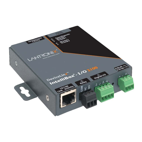
2: Introduction Figure 2-1 IntelliBox-I/O 2100 Device Server (Front) Features The following list summarizes the key features of the IntelliBox-I/O 2100. Monitor events in real-time Automatically respond to events with user-defined actions Query and gather data from attached device (sent to user via email and RSS feed) ... - Page 18 Phone systems (PBX) Fire alarm panels Heating and Air-conditioning (HVAC) PLCs Projectors HVAC (Heating , Ventilation and Air conditioning) Security Cameras Access control panels Proximity Readers Card readers IntelliBox-I/O 2100 User Guide...
-
Page 19: Eventtrak™ Overview
IntelliBox flags the email as "important" and can take preemptive action that the user has defined. Evolution OS™ IntelliBox device servers incorporate Lantronix’s Evolution OS™. Key features of the Evolution OS™ include: Built-in web server for configuration and troubleshooting from web-based browsers ... -
Page 20: Command-Line Interface (Cli)
In addition to keeping data safe and accessible, the IntelliBox has robust defenses to hostile Internet attacks, such as denial of service (DoS), which can take down the network. Moreover, the IntelliBox cannot bring down other devices on the network. IntelliBox-I/O 2100 User Guide... -
Page 21: Troubleshooting Capabilities
2: Introduction The IntelliBox can be used with Lantronix’s Secure Com Port Redirector (SCPR) to encrypt COM port-based communications between PCs and virtually any electronic device. SCPR is a Windows application that creates a secure communications path over a network between the computer and serial-based devices that are traditionally controlled by means of a COM port. -
Page 22: Building Automation/Security
(POS) devices to share information across the network effectively. With the IntelliBox, retailers can increase and streamline productivity quickly and easily by network-enabling serial devices like card swipe readers, bar-code scanners, scales, cash registers, and receipt printers. IntelliBox-I/O 2100 User Guide... -
Page 23: Traffic Management
The product information label on the unit contains the following information about the specific unit: Bar Code Serial Number Part Number Country of Origin Product Revision Hardware Address (MAC Address) Figure 2-1 Product Label IntelliBox-I/O 2100 User Guide... -
Page 24: 3: Eventtrak
IntelliBox can be used. Typical events that the IntelliBox detects include triggers from specific sensors connected to the IntelliBox’s digital inputs and user-specified data detected on the IntelliBox’s serial ports. Following are some examples. IntelliBox-I/O 2100 User Guide... -
Page 25: Other Examples
Preemptively notifies the user of equipment failure. Initiates emergency shutdown or startup. Automatically reports HVAC status (email with attached data). Performs consolidated monitoring of many HVAC systems (RSS feed to a web browser). IntelliBox-I/O 2100 User Guide... -
Page 26: Inputs And Outputs
Wait for a specified amount of time before continuing to the next step Wait for an event to be detected before continuing to the next step Send an initial action at the beginning of each step within a task. For example: IntelliBox-I/O 2100 User Guide... -
Page 27: Automated Reporting
Send a string (or multiple strings) out a serial port Clear the serial line receive buffer Fire a trigger (event) on another task Automated Reporting With the IntelliBox, you can use EventTrak settings to schedule automated reporting of devices. IntelliBox-I/O 2100 User Guide... -
Page 28: 4: Installation
Your IntelliBox-I/O 2100 package includes the following items: One IntelliBox-I/O 2100 device server One DB9F-to-3.5 mm 7-position screw terminal block, RoHS (Lantronix PN 500-172- Note: The serial cable provided is for configuration set-up (female DB9 to be connected to a host computer). -
Page 29: Identifying Hardware Connectors
Figure 4-2 shows the hardware connectors on the back of the IntelliBox. Figure 4-1 Front View of the IntelliBox-I/O 2100 Figure 4-2 Back View of the IntelliBox-I/O 2100 The bottom of the IntelliBox (not shown) has a product information label. This label contains the following information: ... -
Page 30: Screw Terminal Serial Connectors
Web Page, CLI, or XML. Ethernet Port The front panel of the IntelliBox-I/O 2100 provides an RJ45 Ethernet port. This port can connect to an Ethernet (10 Mbps) or Fast Ethernet (100 Mbps) network. There are two bi- color (green/amber) LEDs that indicate speed (10/100 MHz) and activity (full/half duplex). -
Page 31: Terminal Block Power Connector
Figure 4-3.Typical RJ45 Connector Terminal Block Power Connector The front of the IntelliBox-I/O 2100 has a terminal block screw connector for attaching to an appropriate power source, such as those used in automation and manufacturing industries. The terminal block connector supports a power range from 9 to 30 VDC or 9 to 24 VAC. -
Page 32: Relay Port
RX Serial 1 - Green Serial 1 Received Data Activity TX Serial 1 - Amber Serial 1 Transmitted Data Activity RX Serial 2 - Green Serial 2 Received Data Activity TX Serial 2 - Amber Serial 2 Transmitted Data Activity IntelliBox-I/O 2100 User Guide... -
Page 33: Reset Button
Serial port 2 supports RS-422 and RS-485 (4-wire/2-wire) serial devices. Figure 4-4 for pin assignments. To connect the IntelliBox-I/O 2100 to one or more serial devices: Note: We recommend you power off the serial devices that will be connected to the IntelliBox. - Page 34 Figure 4-4 Example of the IntelliBox-I/O 2100 Connections 1. Connect serial devices to screw-down connectors. 2. Connect an Ethernet cable between the IntelliBox-I/O 2100 Ethernet port and your Ethernet network. 3. Attach the power source to the terminal block connector on the front of the IntelliBox.
-
Page 35: 5: Getting Started
Using DeviceInstaller DeviceInstaller is a free utility program provided by Lantronix that discovers, configures, upgrades and manages Lantronix Device Servers. To use the DeviceInstaller utility, first install the latest version from the downloads page on the Lantronix web site www.lantronix.com/downloads. Note: You can also assign an IP address and other basic network settings. -
Page 36: Figure 5-1 Lantronix Deviceinstaller
5: Getting Started Figure 5-1 Lantronix DeviceInstaller IntelliBox-I/O 2100 User Guide... -
Page 37: Viewing Intellibox-I/O 2100 Properties
Enter to complete. Device Family Displays the IntelliBox’s device family type as IntelliBox. Type Displays the device type as IntelliBox I/O 2100. Displays the IntelliBox’s ID embedded within the box. Hardware Address Displays IntelliBox’s hardware (MAC) address. -
Page 38: Configuration Methods
The advantages to this method are ease of use and location independence. With this method, you can configure the IntelliBox from any location that has access to a web browser and the Internet. For more information, see 6: Configuration Using the Web Manager. IntelliBox-I/O 2100 User Guide... -
Page 39: Configuring Via An Ssh/Telnet Session Or Serial Port Using The Cli
IntelliBox serial port. This means the terminal or computer must be in the same location as the IntelliBox. For more information, refer to the IntelliBox-I/O 2100 Command Reference, which is available on the Lantronix web site (www.lantronix.com). -
Page 40: 6: Configuration Using The Web Manager
6: Configuration Using the Web Manager This chapter describes how to configure the IntelliBox-I/O 2100 using the Web Manager, Lantronix’s browser-based configuration tool. The unit’s configuration is stored in nonvolatile memory and retained without power. All changes take effect immediately, unless otherwise noted. -
Page 41: Figure 6-2 Web Manager Device Status Page
PASS. After you log in to the Web Manager, we recommend you use the FTP page to change the default FTP password, see the HTTP Authentication Page change the HTTP authentication password, and the CLI Pages to change the CLI password. Figure 6-2 Web Manager Device Status Page IntelliBox-I/O 2100 User Guide... -
Page 42: Navigating Through The Web Manager
Shows LPD (Line Printer Daemon) Queue statistics and lets you configure the LPD and print a test page. Modbus Displays the current connection status of the Modbus servers listening on the TCP ports and lets you add a second server. IntelliBox-I/O 2100 User Guide... - Page 43 Trivial File Transfer Protocol (TFTP) server. Tunnel Displays the current connection statistics and lets you change the current configuration settings for 2 tunnels for the IntelliBox. Lets you export XML configuration and status records, and import XML configuration records. IntelliBox-I/O 2100 User Guide...
-
Page 44: Figure 6-3 Web Manager Menu Structure (1 Of 5)
Serial String Echo Serial String Signon Message Tunnel Tunnel 1 Statistics Serial Settings Start/Stop Chars Tunnel 2 Accept Mode Connect Mode Disconnect Mode Tunnel 3 Packing Mode Modem Emulation AES Keys Tunnel 4 (continued on next page) IntelliBox-I/O 2100 User Guide... -
Page 45: Figure 6-4 Web Manager Menu Structure (2 Of 5)
6: Configuration Using the Web Manager Figure 6-4 Web Manager Menu Structure (2 of 5) (continued on next page) IntelliBox-I/O 2100 User Guide... -
Page 46: Figure 6-5 Web Manager Menu Structure (3 Of 5)
Max Timeout Log Format Username Authentication Realm Password Auth Type RSS Feed On/Off Persistent Max Entries Statistics Telnet Access Password Telnet Port Configuration Enable Password SSH Access Quick Connect Line SSH Port (continued on next page) IntelliBox-I/O 2100 User Guide... -
Page 47: Figure 6-6 Web Manager Menu Structure (4 Of 5))
6: Configuration Using the Web Manager Figure 6-6 Web Manager Menu Structure (4 of 5)) (continued on next page) IntelliBox-I/O 2100 User Guide... -
Page 48: Figure 6-7 Web Manager Menu Structure (5 Of 5)
6: Configuration Using the Web Manager Figure 6-7 Web Manager Menu Structure (5 of 5) IntelliBox-I/O 2100 User Guide... -
Page 49: Understanding The Web Manager Pages
When you click the name of a page in the menu bar, the page displays in the main area. The main area of most pages contains two sections: IntelliBox-I/O 2100 User Guide... -
Page 50: Device Status Page
Manager. It also displays when you click the Status link in the menu bar. This read-only page shows the IntelliBox product information, network settings, line settings, and tunneling settings. Figure 6-9 Device Status Page (IntelliBox-I/O 2100) IntelliBox-I/O 2100 User Guide... -
Page 51: 7: Network, Serial Line, Tunnel, And Modbus Settings
IntelliBox network configuration settings: BOOTP and DHCP client IP address, network mask, and gateway Hostname and domain DHCP client ID Ethernet transmission speed Figure 7-1 Network Configuration IntelliBox-I/O 2100 User Guide... -
Page 52: Table 7-1 Network Configuration Page Settings
Changing this value requires you to reboot the IntelliBox. Note: When DHCP is enabled, the IntelliBox tries to obtain a network mask from DHCP. If it cannot, the IntelliBox uses a network mask of 255.255.0.0. IntelliBox-I/O 2100 User Guide... - Page 53 IntelliBox to be rebooted. Primary DNS IP address of the primary name server. This entry is required if you choose to configure the DNS (Domain Name Server) servers. Secondary DNS IP address of the secondary name server. IntelliBox-I/O 2100 User Guide...
-
Page 54: Line Settings Pages
Statistics at the top of one of the other Line Settings pages. This read- only page shows the status and statistics for the serial line selected at the top of this page. Figure 7-2 Line – Statistics Page IntelliBox-I/O 2100 User Guide... -
Page 55: Line - Configuration Page
Configuration page displays. This page shows the configuration settings for the serial line selected at the top of the page and lets you change the settings for that serial line. Figure 7-3 Line – Configuration Page IntelliBox-I/O 2100 User Guide... -
Page 56: Table 7-2 Configuration Page
300 baud to 230,400 baud. (Default is 9600 baud.) Custom = lets you enter in the Custom text box a speed other than those shown. Note: Any baud rate over 19200, Lantronix requests flow control usage. Parity Select the parity used by the currently selected serial line. - Page 57 When Flow Control is set to Software, specify Xoff char. Prefix Xoff char a decimal character with \ or a hexadecimal character with 0x, or provide a single printable character. The default Xoff char is 0x13. IntelliBox-I/O 2100 User Guide...
-
Page 58: Line - Command Mode Page
Command Mode page displays. This page shows the command mode settings for the serial line selected at the top of the page and lets you change the settings for that serial line. Figure 7-4 Line – Command Mode Page IntelliBox-I/O 2100 User Guide... -
Page 59: Table 7-3 Line - Command Mode Page
No = does not echo the characters specified in the Serial String text box. Signon Enter a message to send on the serial line at bootup. Select Text or Message Binary to indicate the form of the entry. IntelliBox-I/O 2100 User Guide... -
Page 60: Tunnel Pages
Statistics at the top of one of the other Tunnel pages. This read- only page shows the status and statistics for the tunnel currently selected at the top of this page. Figure 7-5 Tunnel - Statistics Page IntelliBox-I/O 2100 User Guide... -
Page 61: Tunnel - Serial Settings Page
Select Asserted while connected to assert DTR whenever a connect or an accept mode tunnel connection is active. Select Continuously Asserted (default) to assert DTR regardless of the status of a tunnel connection. Unasserted sets DTR off always. IntelliBox-I/O 2100 User Guide... -
Page 62: Tunnel - Start/Stop Characters Page
Start/Stop Chars page displays. This page shows the start and stop characters used for the tunnel selected at the top of the page and lets you change the settings for that tunnel. Figure 7-7 Tunnel – Start/Stop Chars Page IntelliBox-I/O 2100 User Guide... -
Page 63: Table 7-5 Tunnel - Start/Stop Chars Page
Character selected tunnel when the serial line is read. Choices are: On = echo the stop character on the selected tunnel when the serial line is read. Off = do not echo the stop character. (default) IntelliBox-I/O 2100 User Guide... -
Page 64: Tunnel - Accept Mode Page
Here you can select the method for starting a tunnel in Accept Mode and select other settings for the tunnel selected at the top of the page. For more information about Accept Mode, see Accept Mode. Figure 7-8 Tunnel – Accept Mode Page IntelliBox-I/O 2100 User Guide... -
Page 65: Table 7-6 Tunnel - Accept Mode Page
Flush Serial Select whether the serial line is flushed when a connection is made. Choices are: Enabled = flush the serial line when a connection is made. Disabled = do not flush the serial line. (default) IntelliBox-I/O 2100 User Guide... - Page 66 Exclusive Control = same output may not be closed by another condition. Logical-Or = same output may be closed by another condition. RSS Trace Select to enable or disable RSS Trace Connections. Connections IntelliBox-I/O 2100 User Guide...
-
Page 67: Tunnel - Connect Mode Page
Remote Port defaults to Random. If you have configured a specific port number, a Random link displays that enables you to restore the default. For more information about Connect Mode, see Connect Mode. Figure 7-9 Tunnel -- Connect Mode Page IntelliBox-I/O 2100 User Guide... -
Page 68: Table 7-7 Tunnel -- Connect Mode Settings
Connect Mode tunneling. Then, select the key form: Text Hexadecimal AES Decrypt Key Specify the Advanced Encryption Standard (AES) key string to be used for decrypting incoming data in Connect Mode tunneling. Then, select the key form: Text Hexadecimal IntelliBox-I/O 2100 User Guide... - Page 69 (e.g. Connect Mode settings from Tunnel 1 and Tunnel 2 for the same digital port.) Exclusive Control = The same output may not be closed by another condition. Logical-Or = The same output may be closed by another condition. IntelliBox-I/O 2100 User Guide...
-
Page 70: Tunnel - Disconnect Mode Page
Flush Serial Data Select whether the serial line should be flushed when a connection is disconnected. Choices are: Enabled = flush the serial line when a connection is disconnected. Disabled = do not flush the serial line. (default) IntelliBox-I/O 2100 User Guide... -
Page 71: Tunnel - Packing Mode Page
Default is <none>. Trailing Character Enter the trailing character. This character is inserted into the outgoing data stream immediately after the send character. Default is <none>. IntelliBox-I/O 2100 User Guide... -
Page 72: Tunnel - Modem Emulation Page
Tunnel – Modem Emulation page displays. Here you can select modem emulation settings for the tunnel selected at the top of the page. For more information about modem emulation, see Modem Emulation. Tunnel – Modem Emulation Page IntelliBox-I/O 2100 User Guide... -
Page 73: Table 7-10 Tunnel - Modem Emulation Page
If required, enter a customized string that is sent along with the CONNECT response code. Default is <none>. Display Remote IP Select whether to enable an incoming RING followed by the IP address of the caller. Choices are: Enabled Disabled IntelliBox-I/O 2100 User Guide... -
Page 74: Modbus Pages
Protocol Data Units (PDUs) that have been sent and received. This is a count of messages, not bytes. If a connection is active, a Kill link (at its right)) enables you to close the connection. Figure 7-12 Modbus – Statistics Page IntelliBox-I/O 2100 User Guide... -
Page 75: Modbus - Configuration Page
Off = Modbus server is disabled. Additional TCP Enter the number of the TCP port on which the IntelliBox additional server Server Port listens for connections. Response Indicate the response timeout in milliseconds. Must be a minimum of 10 Timeout msec. IntelliBox-I/O 2100 User Guide... -
Page 76: 8: Terminal And Host Settings
This page shows configuration settings for each terminal connection method. You can configure whether each serial line or the telnet/SSH server presents a CLI or a Login Connect manu when a connection is made. Figure 8-1 Terminal on Network and Line IntelliBox-I/O 2100 User Guide... -
Page 77: Table 8-1 Terminal On Network And Line Settings
Select whether to enable echo. Choices are: Enabled Disabled Note: Applies only to Connect Mode Telnet connections, not to Accept Mode. Only disable Echo if your terminal echoes, in which case you will see double of each character typed. Default is enabled. IntelliBox-I/O 2100 User Guide... -
Page 78: Host Configuration
This field appears if you selected SSH as the protocol. Remote Address Enter an IP address for the host to which the device will connect. Remote Port Enter the port on the host to which the device will connect. IntelliBox-I/O 2100 User Guide... -
Page 79: 9: Services Settings
Enter the DNS primary server that maintains the master zone information/file for a domain. Default is <none>. Secondary DNS Enter the DNS secondary server that backs up the primary DNS server for a zone. Default is <none>. DNS Cache Lists the entries in the cache. IntelliBox-I/O 2100 User Guide... -
Page 80: Snmp Page
Under Current Configuration, several settings have a Delete link that lets you delete these settings. If you click these links, a message asks whether you are sure you want to delete this information. Click OK to proceed or Cancel to cancel the operation. Figure 9-2 SNMP Page IntelliBox-I/O 2100 User Guide... -
Page 81: Table 9-2 Snmp Page
On = SNMP cold start trap messages are enabled at boot time. (default) Off = SNMP traps are disabled. Primary Trap Dest IP Enter the primary SNMP trap host. Default is <None>. Secondary Trap Dest IP Enter the secondary SNMP trap host. Default is <None>. IntelliBox-I/O 2100 User Guide... -
Page 82: Ftp Page
On = FTP server is enabled. (default) Off = FTP server is disabled. FTP Username Enter the username required to gain FTP access. Default is admin. FTP Password Enter the password associated with the username. Default is PASS. IntelliBox-I/O 2100 User Guide... -
Page 83: Tftp Page
If you enable this feature, it exposes the IntelliBox to possible Denial-of-Service (DoS) attacks against the filesystem. Choices are: On = files can be created by the TFTP server. Off = files cannot be created by the TFTP server. (default) IntelliBox-I/O 2100 User Guide... -
Page 84: Syslog Page
From the drop-down box, select the minimum level of system message the IntelliBox should log. This setting applies to all syslog facilities. The drop-down list is in descending order of severity, e.g., Emergency is more severe than Alert. IntelliBox-I/O 2100 User Guide... -
Page 85: Http Pages
If you click View, the log displays. If you click Clear, a message asks whether you are sure you want to delete this information. Click OK to proceed or Cancel to cancel the operation. Note: For help changing the format of the log, see Log Format Directives. IntelliBox-I/O 2100 User Guide... -
Page 86: Figure 9-7 Http Configuration Page
9: Services Settings Figure 9-7 HTTP Configuration Page IntelliBox-I/O 2100 User Guide... -
Page 87: Table 9-6 Http Configuration Page
The maximum length for each directive is 64 bytes. The exception is '%r' where each element is limited to 64 bytes (i.e. method, URL path info, and query string). The default log format string is: %h %t "%r" %s %B "%{Referer}i" "%{User-Agent}i" IntelliBox-I/O 2100 User Guide... -
Page 88: Http Authentication Page
The URI, realm, username, and password are user-specified, free-form fields. The URI must match the directory created on the IntelliBox file system. The URI and realm used in the example above are only examples and would typically be different as specified by the user. IntelliBox-I/O 2100 User Guide... -
Page 89: Figure 9-8 Http Authentication Page
Username Enter the name of the user who will participate in the authentication. Default is admin. Password Enter the password that will be associated with the username. Default is PASS. IntelliBox-I/O 2100 User Guide... -
Page 90: Rss Page
Each RSS feed entry is prefixed with a timestamp [BC:HH:MM:SS]. BC is the Boot Cycle value and indicates the number of times the IntelliBox has rebooted since factory defaults were last loaded. The resulting "HH:MM:SS" is the time since the IntelliBox booted. IntelliBox-I/O 2100 User Guide... -
Page 91: Lpd Pages
The LPD web page has three sub-menus for viewing print queue statistics, changing print queue configuration, and printing a test page. Because the LPD lines operate independently, you can specify different configuration settings for each. Figure 9-12 LPD Statistics Figure 9-13 LPD Configuration IntelliBox-I/O 2100 User Guide... -
Page 92: Table 9-9 Lpd Configuration
Queue Name To change the name of the print queue, enter a new name. The name cannot have white space in it and is limited to 31 characters. The default is LPDQueueX (for line number X). IntelliBox-I/O 2100 User Guide... - Page 93 9: Services Settings Figure 9-15 LPD Print Test Page To print an LPD test page 1. Enter the number of lines to print. 2. Click the OK button. IntelliBox-I/O 2100 User Guide...
-
Page 94: 10: Security Settings
Delete links if these keys have been created. If you click View, the key displays. If you click Delete, a message asks whether you are sure you want to delete this information. Click OK to proceed or Cancel to cancel the operation. IntelliBox-I/O 2100 User Guide... -
Page 95: Figure 10-1 Ssh Server: Host Keys Page
10: Security Settings Figure 10-1 SSH Server: Host Keys Page IntelliBox-I/O 2100 User Guide... -
Page 96: Table 10-1 Ssh Server: Host Keys Page
2 minutes for a 1024-bit RSA key 2 minutes for a 512-bit DSA key 10 minutes for a 768-bit DSA key 15 minutes for a 1024-bit DSA key Some SSH clients require RSA host keys to be at least 1024 bits long. IntelliBox-I/O 2100 User Guide... -
Page 97: Ssh Client: Known Hosts Page
Browse button to select the key. Public DSA Key Enter the path and name of the existing public DSA key you want to use with this known host or use the Browse button to select the key. IntelliBox-I/O 2100 User Guide... -
Page 98: Ssh Server: Authorized Users Page
Enter the path and name of the existing public DSA key you want to use with this user or use the Browse button to select the key. If authentication is successful with the key, no password is required. IntelliBox-I/O 2100 User Guide... -
Page 99: Ssh Client: Users Page
Note: If you are providing a key by uploading a file, make sure that the key is not password protected. Figure 10-4 SSH Client: Users Page IntelliBox-I/O 2100 User Guide... -
Page 100: Table 10-4 Ssh Client: Users Page
2 minutes for a 1024-bit RSA key 2 minutes for a 512-bit DSA key 10 minutes for a 768-bit DSA key 15 minutes for a 1024-bit DSA key Some SSH clients require RSA host keys to be at least 1024 bits long. IntelliBox-I/O 2100 User Guide... -
Page 101: Ssl Page
Certificate, there is a Delete link. If you click Delete, a message asks whether you are sure you want to delete the current certificate. Click OK to proceed or Cancel to cancel the operation. Figure 10-5 SSL Page IntelliBox-I/O 2100 User Guide... -
Page 102: Table 10-5 Ssl Page
Common Name would be www.widgets.abccompany.com. Expires Enter the expiration date, in mm/dd/yyyy format, for the new self- signed certificate. Example: An expiration date of May 9, 2007 is entered as 05/05/2007. IntelliBox-I/O 2100 User Guide... - Page 103 15 minutes for a 1024 bit RSA Key 8 minutes for a 512 bit DSA Key 20 minutes for a 768 bit DSA Key 60 minutes for a 1024 bit DSA Key Type Select the type of key: IntelliBox-I/O 2100 User Guide...
-
Page 104: 11: Maintenance And Diagnostics Settings
Only a system administrator should perform these tasks. Note: Compact preserves data and eliminates dirty space by making a new copy. Format destroys all of the data in the filesystem. Figure 11-1 Filesystem Statistics Page IntelliBox-I/O 2100 User Guide... -
Page 105: Filesystem Browser Page
Here you can browse and manipulate the entire filesystem. For example, you can: Browse the filesystem. Create files and directories. Upload files via HTTP. Copy and move files. Transfer files to and from a TFTP server. Figure 11-2 Filesystem Browser Page IntelliBox-I/O 2100 User Guide... -
Page 106: Table 11-1 Filesystem Browser Page
(“get’) or externally (“put”). Host Enter the IP address or name of the host involved in this operation. Port Enter the number of the port involved in TFTP operations. Click Transfer to complete the TFTP transfer. IntelliBox-I/O 2100 User Guide... -
Page 107: Diagnostics Pages
The Diagnostics: Hardware page displays when you click Diagnostics in the menu bar. It also displays when you click Hardware at the top of one of the other Diagnostic pages. This read-only page displays the current hardware configuration. Figure 11-3 Diagnostics: Hardware Page IntelliBox-I/O 2100 User Guide... -
Page 108: Mib-Ii Network Statistics Page
RFC 2011, Updated definitions for IP and ICMP RFC 2012, Updated definitions for TCP RFC 2013, Updated definitions for UDP RFC 2096, Definitions for IP Forwarding Figure 11-4 Diagnostics: MIB-II Network Statistics Page IntelliBox-I/O 2100 User Guide... -
Page 109: Ip Sockets Page
IP Sockets Page Clicking IP Sockets from one of the Diagnostics pages displays the IP Sockets page. This read-only page lists all the network sockets on the IntelliBox that are currently open. Figure 11-5 Diagnostics: IP Sockets Page IntelliBox-I/O 2100 User Guide... -
Page 110: Diagnostics: Ping Page
Enter the number of ping packets that the IntelliBox should try to send to the Host. Default is 3. Timeout Enter the maximum number of seconds that the IntelliBox should wait for a response from the host before timing out. Default is 5 seconds. IntelliBox-I/O 2100 User Guide... -
Page 111: Diagnostics: Traceroute Page
Figure 11-7 Diagnostics: Traceroute Page Table 11-3 Diagnostics: Traceroute Page Diagnostics: Description Traceroute Page Settings Host Enter the IP address or DNS host name of the remote host that you want to traceroute from the IntelliBox. IntelliBox-I/O 2100 User Guide... -
Page 112: Diagnostics: Dns Lookup Page
For reverse lookup to locate the hostname for that IP address, enter an IP address. For forward lookup to locate the corresponding IP address, enter a hostname. To look up the Mail Exchange (MX) record IP address, enter a domain name prefixed with @. IntelliBox-I/O 2100 User Guide... -
Page 113: Diagnostics: Memory Page
This read-only page shows the total memory and available memory (in bytes), along with the number of fragments, allocated blocks, and memory status. The Diagnostics: Memory page also shows the current amount of available memory. Figure 11-9 Diagnostics: Memory Page IntelliBox-I/O 2100 User Guide... -
Page 114: Diagnostics: Buffer Pool
Private buffer pools are used in various parts of the system to ensure deterministic memory management, thus eliminating any contention for memory from the generic heap space. Figure 11-10 Diagnostics: Buffer Pools Page IntelliBox-I/O 2100 User Guide... -
Page 115: Diagnostics: Processes Page
The CPU % column displays the percentage of total CPU cycles a process used in the last two seconds. The Stacks column displays the total stack space available to the process and the maximum amount of the stack space the process used since it was started. IntelliBox-I/O 2100 User Guide... -
Page 116: Figure 11-11 Diagnostics: Processes Page
11: Maintenance and Diagnostics Settings Figure 11-11 Diagnostics: Processes Page Below the process chart is a CPU Load Graph that shows the CPU load over the last five minutes. The IntelliBox generates the graph using the Scalable Vector Graphics (SVG) IntelliBox-I/O 2100 User Guide... -
Page 117: Figure 11-12 System
Clicking the System link in the menu bar displays the System page. Here you can: Reboot the IntelliBox. Restore factory defaults. Upload new firmware. Assign short and long names to the IntelliBox. Change time settings. Figure 11-12 System Page IntelliBox-I/O 2100 User Guide... -
Page 118: Figure 11-13 Query Port
Name Enter the short name and long name for the IntelliBox. Default short name is IntelliBoxio and default long name is Lantronix IntelliBox. Query Port Page Clicking the Query Port link in the menu bar displays the Query Port page. This page displays statistics and current usage information about the query port server. -
Page 119: Table 11-6 Query Port Page
Table 11-6 Query Port Page Query Port Description Page Settings Query Port Server Select whether the query port server is enabled or disabled. Choices are: On = query port server is enabled. (default) Off = query port server is disabled. IntelliBox-I/O 2100 User Guide... -
Page 120: 12: Advanced Settings
The Input/Output page displays when you click Input/Output in the menu bar. A Submit button displays if you modify either a direction or a control. Clicking Submit applies changes immediately to the IntelliBox. Figure 12-1 Input Output Page IntelliBox-I/O 2100 User Guide... -
Page 121: Table 12-1 Input/Output Page
A change in the state of a pin triggers the IntelliBox to send an RSS feed. Primarily used for troubleshooting. RSS Trace transitions are visible when XI01/XI02 are set to the Input option. Note: The Relay is an output port only. IntelliBox-I/O 2100 User Guide... -
Page 122: Email Pages
From the Select Email drop-down list at the top of the page, select the email whose configuration you want to view. The number of emails is the number of email configurations available. For example, if the highest email number available is four, then four different email addresses can be used. IntelliBox-I/O 2100 User Guide... -
Page 123: Figure 12-3 Email Configuration
12: Advanced Settings Figure 12-3 Email Configuration Page IntelliBox-I/O 2100 User Guide... -
Page 124: Table 12-2 Email Configuration Page
Select the priority level for the email alert. Trigger Email Send Select the condition that serves as a trigger for sending an email. To test your configuration, you can send an email immediately by clicking Send Email at the top of the page. IntelliBox-I/O 2100 User Guide... -
Page 125: Cli Pages
The remote client information displays. The number of bytes that have been sent and received displays. A Kill link can be used to terminate the connection. Figure 12-4 Command Line Interface Statistics Page IntelliBox-I/O 2100 User Guide... -
Page 126: Command Line Interface Configuration Page
Under Current Configuration, Password has a Delete link at its right. If you click Delete, a message asks whether you are sure you want to delete this information. Click OK to proceed or Cancel to cancel the operation. IntelliBox-I/O 2100 User Guide... -
Page 127: Table 12-3 Command Line Interface Configuration Page
The SSH Server Authorized Users are used for initial login access. See SSH Server: Authorized Users Page. SSH Port Enter the number of the port on which the IntelliBox listens for incoming SSH connections. Default is 22. IntelliBox-I/O 2100 User Guide... - Page 128 <line> and subsequent characters go out the selected line and a subsequent display comes from characters received on the line. This mode ends after you type this string (e.g., <control>L). The CLI command mode returns. IntelliBox-I/O 2100 User Guide...
-
Page 129: Xml Pages
By default, all groups are selected except those pertaining to the network configuration (Ethernet and interface). This is so that if you later export the entire XML configuration, it will not break your network connectivity. You may select or clear the checkbox for any group. IntelliBox-I/O 2100 User Guide... -
Page 130: Figure 12-6 Xml Configuration Record: Export System Configuration
12: Advanced Settings Figure 12-6 XML Configuration Record: Export System Configuration Page IntelliBox-I/O 2100 User Guide... -
Page 131: Xml Status Record: Export System Status
If you click XML Status Record at the top of an XML page, the XML Status Record: Export System Status page displays. Here you can export the current system status in XML format. The XML data can be exported to the browser window or to a file on the filesystem. IntelliBox-I/O 2100 User Guide... -
Page 132: Table 12-5 Xml Status Record: Export System Status Page
Check the instances to be exported in the event trak, line, lpd, serial, tunnel and terminal groups. Groups to Export Check the configuration groups that are to be exported into the XML status record. If no groups are checked, all groups will be exported. IntelliBox-I/O 2100 User Guide... -
Page 133: Xml: Import System Configuration Page
Each group name <g> is followed by a colon and the instance value <i>. Each <g> :<i> value is separated with a semicolon. If a group has no instance, specify the group name <g> only. Figure 12-8 XML: Import System Configuration Page IntelliBox-I/O 2100 User Guide... -
Page 134: Table 12-6 Xml: Import System Configuration Page
If required, enter the filter string for importing specific instances of a Instances to Import group. Whole Groups to Check the configuration groups that are to be imported into the XML Import configuration record. If no groups are checked, all groups will be imported. IntelliBox-I/O 2100 User Guide... -
Page 135: Figure 12-9 Protocol Stack Page (Tcp)
Send Data Determine when data may be sent to the network. Choices are: Standard = waits for an ACK before sending a packet less than the maximum length. Expedited = sends data whenever the window allows it. IntelliBox-I/O 2100 User Guide... -
Page 136: Figure 12-10 Protocol Stack Page (Ip)
Internet Control Message Protocol (ICMP) can be used as an error-reporting protocol between two hosts. This setting specifies whether incoming and outgoing ICMP messages are processed. Choices are: Enabled = ICMP messages are processed. (default) Disabled = ICMP messages are not processed. IntelliBox-I/O 2100 User Guide... -
Page 137: Figure 12-12 Protocol Stack Page (Arp)
ARP Cache IP Address Enter the IP address of the entry to be added to the Address Resolution Protocol (ARP) cache. MAC Address Enter the MAC address of the entry to be added to the ARP cache. IntelliBox-I/O 2100 User Guide... -
Page 138: Figure 12-13 Ip Address Filter
Enter the IP address that is allowed to send packets to the IntelliBox. If using DHCP with BOOTP, enter the IP address of the DHCP/BOOTP server. Network Mask Enter the network mask associated with the IP address that is allowed to send packets to the IntelliBox. IntelliBox-I/O 2100 User Guide... -
Page 139: 13: Eventtrak Pages
Additionally, the IntelliBox provides automatic reporting and RSS feeds. On the IntelliBox-I/O 2100, there is one EventTrak for each of the two serial lines. After you select an EventTrak, you can click Status, Monitoring, or Control to view and change the settings of the selected EventTrak. -
Page 140: Eventtrak - Status Page
Table 13-1 EventTrak -- Status Page EventTrak Status Description Page Task Description Text identifying the task. Current Step Letter identifying the currently active step. Step Name Text identifying the step. Duration Length of time the IntelliBox has been performing the step. IntelliBox-I/O 2100 User Guide... -
Page 141: Eventtrak - Monitoring Page
Match string EventTrak monitors activity on each line, comparing to the match string at all times. Enter the match string you want the IntelliBox to use to monitor the line. You can use text or binary format. IntelliBox-I/O 2100 User Guide... - Page 142 Select the option that indicates whether the match must be case sensitive. RSS Trace Select the checkbox to cause EventTrak to send information by means of RSS when it encounters a string match. This function is primarily for troubleshooting. IntelliBox-I/O 2100 User Guide...
-
Page 143: Match String Examples
In this example, the match string is set to allow EventTrak to monitor for any string that contains the word error followed by any 4 characters. This is an example of a simple text-based match string with an asterisk as a wild card character. IntelliBox-I/O 2100 User Guide... -
Page 144: Eventtrak - Control Page
At the top of the page, select Task 1, Task 2, or Task 3 to display a Control page for each task you want to configure. IntelliBox-I/O 2100 User Guide... -
Page 145: Figure 12-3 Eventtrak Control
I/O is set as an output. The Output Control options display (See description in this table.) Relay = assigns the relay to a task to be controlled. The Output Control options display. (See description in this table.) IntelliBox-I/O 2100 User Guide... - Page 146 Each step consists of two to four configurable items, depending on the options selected. For example, if you select Relay as the initial activity, you must select the initial relay setting at the beginning of Step “A” as shown in the example below. IntelliBox-I/O 2100 User Guide...
-
Page 147: Table 13-4 Eventtrak Control Step Settings
Send Email = tells EventTrak to send an email when it detects an event. When you select an option, the following additional configurable items display: No Email removes Send email as an action in response IntelliBox-I/O 2100 User Guide... - Page 148 Fire Trigger = fires a trigger on another task. When selected, the following additional configurable items display. Choices are: No Trigger removes the Fire Trigger option as an action IntelliBox-I/O 2100 User Guide...
- Page 149 Task 2. Task 2 can be triggered by setting its Advance to or Fallback to configurable to Triggered by task 1. Note: For examples of using EventTrak for event monitoring and automated reporting, please go to http://www.lantronix.com/support. IntelliBox-I/O 2100 User Guide...
-
Page 150: 14: Updating Firmware
FTP (ftp://ftp.lantronix.com/). Upgrading Using DeviceInstaller Loading New Firmware 1. Download the latest firmware and release notes for IntelliBox-I/O 2100 from the Lantronix web site http://www.lantronix.com/support/downloads.html. 2. Unzip the files and save them to a directory on your PC Updating Firmware 1. -
Page 151: Cli Settings
Telnet Access Enabled Telnet Port SSH Access Enabled SSH Port Password <None> Enable Password <None> Quit Connect Line <control>L Diagnostics Settings Table A-2 Diagnostic Ping Settings Diagnostics Ping Diagnostic Ping Settings Parameters Count Timeout 5 seconds IntelliBox-I/O 2100 User Guide... -
Page 152: Email Settings
Priority Normal Trigger Email Send Disabled EventTrak Settings Table A-4 Monitoring Settings EventTrak EventTrak Monitoring Settings Monitoring Parameters <None> Match String Text Mode of string Wildcard character <None> Timeout Milliseconds 60000 Case sensitive RSS Trace <None> IntelliBox-I/O 2100 User Guide... -
Page 153: Ftp Settings
HTTP Settings Table A-7 HTTP Settings HTTP Configuration HTTP Settings Parameters HTTP Server HTTP Port HTTPS Port Max Timeout 10 seconds Max Bytes 40960 Logging Max Log Entries Log Format %h %t "%r" %s %B "%{Referer}i" "%{User-Agent}i" IntelliBox-I/O 2100 User Guide... -
Page 154: Input/Output Settings
Output IP Address Filter Settings Table A-10 IP Address Settings IP Address IP Address Settings Parameters IP Address <None> Network Mask <None> Modbus Settings Table A-11 Modbus Settings Modbus Parameters Modbus Settings TCP Server Access Enabled IntelliBox-I/O 2100 User Guide... -
Page 155: Network Configuration Settings
MAC Address Specified by manufacturer Hostname <None> Domain <None> DHCP Client ID <None> Ethernet lINK Auto speed, auto duplex Query Port Settings Table A-13 Query Port Settings Query Port Query Port Settings Parameters Query Port Server IntelliBox-I/O 2100 User Guide... -
Page 156: Rss Settings
Serial Port Line Configuration Settings Parameters Name <None> Status Enabled Protocol Tunnel Interface Disabled Termination Disabled Baud Rate 9600 baud Parity <None> Data Bits Stop Bits Flow Control <None> Xon char 0x11 (\17) Xoff char 0x13 (\19) IntelliBox-I/O 2100 User Guide... -
Page 157: Command Mode
SNMP Parameters SNMP Settings SNMP Agent Running Read Community Public Write Community Private System Contact <None> System Name ibio2100 System Description Lantronix IntelliBox-I/O 2100 System Location <None> Enable Traps Primary TrapDest IP <None> Secondary TrapDest IP <None> IntelliBox-I/O 2100 User Guide... -
Page 158: Syslog Settings
<None> System Settings Table A-19 System Settings System Parameters System Settings System Name ibio2100 System Description Lantronix IntelliBox-I/O 2100 TFTP Settings Table A-20 TFTP Settings TFTP Parameters TFTP Settings TFTP Server Allow TFTP File Disabled Creation IntelliBox-I/O 2100 User Guide... -
Page 159: Tunnel Settings
Accept Mode Settings Accept Mode Enabled Local Port Port 1 = 10001, Port 2 = 10002 Protocol Flush Serial Data Disabled Block Serial Data Block Network Data TCP Keep Alive 45 seconds Email on Connect <None> IntelliBox-I/O 2100 User Guide... -
Page 160: Connect Mode
Protocol Reconnect Timer 15000 milliseconds Flush Serial Data Disabled SSH Username <None> Block Serial Data Block Network Data TCP Keep Alive 45 seconds Email on Connect <None> Email on Disconnect <None> Output Selection <None> Control Exclusive IntelliBox-I/O 2100 User Guide... -
Page 161: Disconnect Mode
Send Character <None> Trailing Character <None> Modem Emulation Table A-27 Modem Emulation Settings Modem Emulation Modem Emulation Settings Parameters Echo Pluses Echo Commands Verbose Response Codes Response Codes Text Error Unknown Commands Optional Connect String <None> IntelliBox-I/O 2100 User Guide... -
Page 162: Aes Keys
Table A-28 AES Key Settings AES Key Parameters AES Key Settings Accept Mode AES Keys: Encrypt <None> Accept Mode AES Keys: Decrypt <None> Connect Mode AES Keys: <None> Encrypt Key Connect Mode AES Keys: <None> Decrypt Key IntelliBox-I/O 2100 User Guide... -
Page 163: Ssl
Reduces the complexities associated with keeping user information confidential Works with existing web servers and browsers Eliminates the need for additional software applications Provides high level of security Platform and O/S neutral Allows server authentication via certificates IntelliBox-I/O 2100 User Guide... -
Page 164: How Ssl Works
Certificate Authority who issued the certificate, the root and the country it was issued in. In addition to proving the veracity of a site, the Digital IntelliBox-I/O 2100 User Guide... -
Page 165: Ssh
Interception of cleartext passwords and other data by intermediate hosts. Manipulation of data by people in control of intermediate hosts. Attacks based on listening to authentication data and spoofed connections to the server. IntelliBox-I/O 2100 User Guide... -
Page 166: Tunneling
PC’s serial port and received at the remote PC. In this way, serial data that goes in one end comes out at the other end. Figure B-1 Example of an Encrypted Tunnel IntelliBox-I/O 2100 User Guide... -
Page 167: Tunneling And The Intellibox
To configure SSH, you must configure the SSH client username. In Connect Mode, the IntelliBox is the SSH client. Ensure the IntelliBox SSH client username is configured on the SSH server before using it with the IntelliBox. IntelliBox-I/O 2100 User Guide... -
Page 168: Accept Mode
Active if it receives a specific (configurable) character from the serial port (same start character as Connect Mode’s start character) Modem control signal (when the modem control on the serial line corresponding to the tunnel becomes active) IntelliBox-I/O 2100 User Guide... -
Page 169: Disconnect Mode
B: Networking and Security Disconnect Mode Disconnect Mode ends Accept Mode and Connect Mode connections. When disconnecting, the IntelliBox-I/O 2100 shuts down connections gracefully. Tunnel Disconnect Mode allows multiple simultaneous options. The following three settings end a connection: The IntelliBox receives the stop character. -
Page 170: Command Mode
For the following examples, we assume that the remote address is 192.168.16.10 and the port is set to 10001 in the Connect Mode settings: Entering ATDT alone causes the IntelliBox to connect to the IP address and remote port configured in Connect Mode. IntelliBox-I/O 2100 User Guide... - Page 171 If you add 10012 after the IP address segment, port 10012 is used instead of the port defined in Connect Mode. By default, the +++ characters are not passed through the connection. To pass them through the connection, enable Echo Pluses on the Tunnel - Modem Emulation page. IntelliBox-I/O 2100 User Guide...
-
Page 172: Overview
Modbus/ASCII serial devices with newer TCP/IP network-based devices. This appendix describes a system that integrates three Modbus/RTU slave devices with four Modbus/TCP devices. Table C-1 Extended Modbus System Example Modbus/TCP over Ethernet, Token Ring, Routers, WAN, etc. IntelliBox-I/O 2100 IntelliBox-I/O 2100 RS-232 RS-422 RS-485 IntelliBox-I/O 2100 User Guide... -
Page 173: Examples
F and G. IntelliBox manages and coordinates the shared access. In fact, the IntelliBox allows up to sixteen concurrent Modbus masters (or thirty-two if an additional TCP Server is also used) to share access to the slaves. IntelliBox-I/O 2100 User Guide... -
Page 174: Local Slave
Write Multiple Coils Write Multiple Registers Read/Write Multiple Registers 43/14 Read Device Identification (Basic) Note: Any attempt to write to an XIO that the user has configured as an input returns exception 4 (slave device failure). IntelliBox-I/O 2100 User Guide... -
Page 175: Table D-1 Technical Specifications
D: Technical Specifications Table D-1 Technical Specifications Category IntelliBox-I/O 2100 Specifications Lantronix’s DSTni-EX controller with 256 KB SRAM, 16 KB of boot ROM, and an integrated AMD 10/100B Ethernet PHY 4 MB Flash Flash 2 MB SRAM 64 Kbits EEPROM Upgradeable via the Web Manager, TFTP, or FTP;... - Page 176 Transient voltage protection and ESD at power input with max non-repetitive surge current 800 A 8/20 us) (IEC 61000-4-2) Transient voltage protection and ESD with max non-repetitive surge power 600W peak (10/1000 us) at digital I/O ports IntelliBox-I/O 2100 User Guide...
- Page 177 IEC_61000-4-11: 1994 UL 60950-1 Safety Standards CSA 22.2. No 60950-1-03 EN 60950-1 VCCI C-Tick FCC Part 15 Statement Class A Device, ICES-003 Class A Device, C-Tick, VCCI, CE Product Label Marking, UL-CUL Mark, TUV-GS Mark Markings IntelliBox-I/O 2100 User Guide...
-
Page 178: Absolute Maximum Ratings
V = 3V. 4. For V > 10 VDC an external series resistor is required as shown in Table C-1. 5. Connect RELAY and DIGITAL IO Ports only to Class III or Class 2 circuit. IntelliBox-I/O 2100 User Guide... -
Page 179: Electrical Characteristics
4. For VI = VIH > 10 VDC an external series resistor is required as shown in Table C-1. 5. Connect RELAY and DIGITAL IO Ports only to Class III or Class 2 circuit. Figure C-1 Optically Isolated I/O Configured as an Output with Solid State Relay IntelliBox-I/O 2100 User Guide... - Page 180 Figure C-4 Isolated General Purpose Input Application Circuit Note: For input close to or higher than Absolute Maximum Rating value, use a series resistor Rext as in Figure C-4. Table C-1 has the tabulated values for Rext in such cases. IntelliBox-I/O 2100 User Guide...
-
Page 181: Table E-1 Rext Values
11.2 11.9 12.6 13.2 13.9 14.6 15.2 15.9 16.6 17.2 17.9 The Rext resistor limits the current I to about 1.5 mA, and Rext is 1/4W. Figure C-5. Relay Contact position when not energized (power off) IntelliBox-I/O 2100 User Guide... - Page 182 E: Isolated I/O Specifications Figure C6 Relay Contact position when energized IntelliBox-I/O 2100 User Guide...
- Page 183 Advance to Step “1D” If: Advance to Step “2D” If: Advance to Step “3D” If: Advance to Step “1A” If: Advance to Step “2A” If: Advance to Step “3A” If: Step 1D: Step 2D: Step 3D: IntelliBox-I/O 2100 User Guide...
- Page 184 Description of the problem Debug report (stack dump), if applicable Status of the unit when the problem occurred (please try to include information on user and network activity at the time of the problem) IntelliBox-I/O 2100 User Guide...
-
Page 185: Declaration Of Conformity
H: Compliance Declaration of Conformity (according to ISO/IEC Guide 22 and BS 7514) Manufacturer’s Name & Address: Lantronix, 167 Technology Drive, Irvine, CA 92618 USA Declares that the following product: Product Name Model: IntelliBox-I/O 2100 2 Port Industrial Device Server... - Page 186 Radio Disturbance Characteristics of Information Technology Equipment. The product complies with the requirements of the Low Voltage Directive 72/23/EEC and the EMC Directive 89/336/EEC. Manufacturer’s Contact: Lantronix 167 Technology Drive, Irvine, CA 92618 USA Tel: 949-453-3990 Fax: 949-453-3995 IntelliBox-I/O 2100 User Guide...
- Page 187 I: Warranty For details on the Lantronix warranty replacement policy, go to our web site at www.lantronix.com/support/warranty. IntelliBox-I/O 2100 User Guide...
- Page 188 Host key settings, SSH server, 94 Buffer pool, 116 DNS lookup, 114 HTTP pages, 85 Hardware, 109 Authentication, 88 IP sockets, 111 Configuration, 85 Memory, 115 Statistics, 85 Uploading a file to the filesystem, 106 MIB-II network statistics, 110 IntelliBox-I/O 2100 User Guide...
- Page 189 TFTP page, 83 Web Manager, 42 TFTP server, transferring files, 106 Network Configuration page, 51 Traceroute, 113 Obtaining firmware, 152 Transferring files to/from a TFTP server, Packing mode, 71, 171 Pinging an IP address, 112 Tunnel pages IntelliBox-I/O 2100 User Guide...
- Page 190 Modbus, 74 Overview, 38 Page components, 49 Configuration, 39 Web Manager pages XML pages, 131 CLI, 127 Export system configuration record, 131 Device Status, 50 Export system status, 133 Diagnostics, 109 Import system configuration record, 135 IntelliBox-I/O 2100 User Guide...
Need help?
Do you have a question about the I/O 2100 and is the answer not in the manual?
Questions and answers