Table of Contents
Advertisement
Advertisement
Table of Contents

Related Manuals for Lantronix UDS2100


Summary of Contents for Lantronix UDS2100
- Page 1 UDS2100 Device Server User Guide Part Number 900-448 Revision F June 2015...
-
Page 2: Intellectual Property
Intellectual Property © 2015 Lantronix. All rights reserved. No part of the contents of this book may be transmitted or reproduced in any form or by any means without the written permission of Lantronix. Lantronix is a registered trademark and DeviceInstaller is a trademark of Lantronix. -
Page 3: Revision History
Monitor Mode commands and diagrams of mounting brackets. August 2008 Updated for firmware version 6.6.0.0. January 2009 Reference to documentation on Lantronix website; minor corrections October 2012 Updated for firmware version 6.8.0.0. June 2015 Updated for firmware version 6.11.0.0. -
Page 4: Table Of Contents
Installing DeviceInstaller ________________________________________ 18 Assigning an IP Address _______________________________________ 18 Adding the Unit to the Manage List _______________________________ 19 Accessing the UDS2100 Using DeviceInstaller ______________________ 19 Viewing the Current Configuration ________________________________ 19 Next Step ________________________________________________ 21 Assigning the IP Address: Serial Port Login _________________________ 22... - Page 5 Remote Port ______________________________________________ 55 DisConnMode _____________________________________________ 55 Flush Mode (Buffer Flushing) _________________________________ 56 Pack Control ______________________________________________ 57 Packing Interval ___________________________________________ 58 Trailing Characters _________________________________________ 58 Send Characters ___________________________________________ 58 DisConnTime (Inactivity Timeout) _____________________________ 58 Send Characters ___________________________________________ 58 UDS2100 Device Server User Guide...
- Page 6 Recovering the Firmware Using the Serial Port and DeviceInstaller ___ 67 11: Monitor Mode Entering Monitor Mode Using the Serial Port _____________________ 69 Entering Monitor Mode Using the Network Port ___________________ 69 Monitor Mode Commands ___________________________________ 69 UDS2100 Device Server User Guide...
- Page 7 AutoIP ______________________________________________________ 84 BOOTP _____________________________________________________ 85 ARP and Telnet ______________________________________________ 85 F: Binary to Hexadecimal Conversions Converting Binary to Hexadecimal ________________________________ 86 Conversion Table __________________________________________ 86 Scientific Calculator ________________________________________ 87 G: Compliance RoHS Notice ______________________________________________ 89 Index UDS2100 Device Server User Guide...
-
Page 8: List Of Figures
Figure 2-2. Direct TCP/IP or Redirector Configuration _________________________ 12 Figure 2-3. Product Label _______________________________________________ 14 Figure 3-1. UDS2100 Connected to Serial Device and Network _________________ 15 Figure 5-1. Web Manager Login Window ___________________________________ 24 Figure 5-2. Lantronix Web Manager _______________________________________ 24 Figure 5-3. -
Page 9: 1: Using This Guide
1: Using This Guide Purpose and Audience This guide provides the information needed to configure, use, and update the UDS2100 device server. It is for system administrators and those responsible for installing and maintaining the UDS. Chapter Summary The remaining chapters in this guide include:... -
Page 10: Additional Documentation
Document Description UDS2100 Quick Start Provides the steps for getting the UDS2100 up and running. DeviceInstaller Online Provides instructions for using the Windows-based utility to Help configure the UDS2100 and other Lantronix device servers. -
Page 11: 2: Introduction
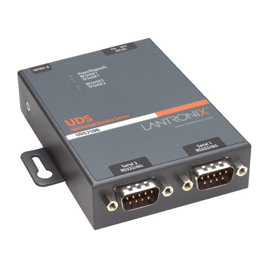
2: Introduction The UDS2100 is a 2-port device server that provides a quick, simple, and cost- effective way to bring the advantages of data accessibility and remote management to devices not currently connected to a network. Applications The UDS family of Device Servers allows serial devices, such as those listed... -
Page 12: Figure 2-1. Serial Tunneling Example
Figure 2-2. Direct TCP/IP or Redirector Configuration Note: For step-by-step instructions on configuring the UDS for serial tunneling or for use with the Com Port Redirector, see UDS Configuration Tutorials on the Lantronix web site: www.lantronix.com/support. UDS2100 Device Server User Guide... -
Page 13: Protocol Support
Setup Mode: making a Telnet connection to the network port (9999) or connecting a terminal (or a PC running a terminal emulation program) to the unit’s serial port. See 6: Configuration via Telnet or Serial Port (Setup Mode). UDS2100 Device Server User Guide... -
Page 14: Product Information Label
Bar Code Part Number Revision Manufacturing Date Code Serial Number (also the hardware Address or MAC Address) Figure 2-3. Product Label Bar Code Part Number Manufacturing Date Code Serial Number Revision UDS2100 Device Server User Guide... -
Page 15: 3: Installation Of Uds2100
3: Installation of UDS2100 This chapter describes how to install your UDS2100 and get it up and running in the shortest possible time. Package Contents Verify and inspect the contents of the UDS2100 package using the following list. If any item is missing or damaged, contact your place of purchase immediately. -
Page 16: Required Information
Hardware Address: 00 – 20 - 4a - _____ - _____ - _____ Hardware Address: 00 - 80 - A3 - _____ - _____ - _____ Note: Make note of the MAC address. It is needed to locate the UDS2100 module using DeviceInstaller. IP Address The UDS must have a unique IP address on your network. - Page 17 DeviceInstaller (graphical user interface) and serial port login (command line interface) methods. Note: For information about other methods of assigning the IP address, such as DHCP, AutoIP, ARP, and Telnet, see E: Alternative Ways to Assign an IP Address. UDS2100 Device Server User Guide...
-
Page 18: 4: Using Deviceinstaller
4: Using DeviceInstaller This chapter covers the steps for getting the UDS2100 device server online and for viewing its current configuration. Note: DeviceInstaller is a free utility program provided by Lantronix that discovers, configures, upgrades, and manages Lantronix Device Servers. -
Page 19: Adding The Unit To The Manage List
Click the Close button to close the dialog box and return to the main window. Adding the Unit to the Manage List Now add the unit to the list of similar Lantronix devices on the network so you can manage and configure it. To perform this step, click the Search icon DeviceInstaller locates the unit and adds it to the list. - Page 20 PCs or laptops using DeviceInstaller. DHCP Device Name Non-configurable field. Displays the name associated with UDS2100’s current IP address, if the IP address was obtained dynamically. To change the DHCP device name, see Configuration Using Web Manager Configuration via Telnet or Serial Port (Setup Mode).
-
Page 21: Next Step
Maximum Baud Non-configurable field. Displays the UDS2100’s maximum baud Rate Supported rate. Note: The UDS2100 may not currently be running at this rate. Firmware Non-configurable field. Displays True, indicating the UDS2100’s Upgradeable firmware is upgradeable as newer version become available. -
Page 22: Assigning The Ip Address: Serial Port Login
Enter the new IP address, subnet mask, and gateway (if applicable). Do one of the following: Continue with 6: Configuration via Telnet or Serial Port (Setup Mode). Select 9 to save and exit Setup Mode. The unit performs a power reset. UDS2100 Device Server User Guide... -
Page 23: 5: Configuration Using Web Manager
Run DeviceInstaller and search for the list of available Lantronix device servers. Click on the UDS folder. The list of available UDS products display. Expand the list of UDS2100s by clicking the + symbol next to the UDS2100 icon. Select the UDS2100 unit by clicking its hardware address. -
Page 24: Figure 5-1. Web Manager Login Window
If a telnet password has been defined, leave the username blank, type in the password, and then click OK. The Web Manager displays. Figure 5-2. Lantronix Web Manager The main menu is in the left pane of the Web Manager window. UDS2100 Device Server User Guide... -
Page 25: Network Configuration
Click Network from the main menu. Note the following: Network Mode For the UDS2100, Wired Only is the only choice. It enables the Ethernet network connectivity. Automatic IP Address Configuration An IP address can be assigned automatically. You then enter related network settings. -
Page 26: Static Ip Address Configuration
(DHCP) to assign a leased IP address to the UDS2100 unit automatically. Enable is the default. AutoIP Select Enable to permit the UDS2100 to generate an IP in the 169.254.x.x address range with a Class B subnet. Enable is the default. -
Page 27: Ethernet Configuration
When you are finished, click the OK button. On the main menu, click Apply Settings. Server Configuration The unit’s server values display when you select Server from the main menu. The following sections describe the configurable parameters on the Server Settings page. UDS2100 Device Server User Guide... -
Page 28: Figure 5-4. Server Settings
5: Configuration Using Web Manager Figure 5-4. Server Settings To configure the UDS2100 device server settings: On the main menu, click Server. Configure or modify the following fields: Server Configuration Enhanced Password Select whether to enable advanced password: Enable: selecting this option enables advanced password creation, allowing you to create passwords up to 16 bytes in length. -
Page 29: Host List Configuration
On the main menu, click Apply Settings. Host List Configuration The UDS2100 scrolls through the host list until it connects to a device listed in the host list table. After a successful connection, the unit stops trying to connect to any others. If this connection fails, the unit continues to scroll through the table until the next successful connection. -
Page 30: Channel 1 And Channel 2 Configuration
Figure 5-5. Hostlist Settings Enter or modify the following fields: Retry Settings Retry Counter Enter the value for the number of times the UDS2100 should attempt to retry connecting to the host list. The default setting is 3. Retry Timeout Enter the duration (in milliseconds) the UDS2100 should abandon attempting a connection to the host list. -
Page 31: Figure 5-6. Channel Serial Settings
Valid baud rates are 300, 600, 1200, 2400, 4800, 9600 (default), 19200, 38400, 57600, 115200, 230400, 460800, and 921600 baud. The default setting is 9600. Note: Baud rates 460800 and 921600 are available for selection only when CPU performance mode is set to High." UDS2100 Device Server User Guide... - Page 32 Use to indicate the end of a series of data to be sent as one group. The sequence must occur sequentially to indicate end of the data collection to the UDS2100. The default setting is Match Bytes Use to indicate the end of a series of data to be sent as one group.
-
Page 33: Connection Settings - Tcp
To configure a channel’s TCP settings: On the main menu, click Connection. The Connection Settings window for the channel displays. Figure 5-7. TCP Connection Settings In the available fields, enter or modify the following information: UDS2100 Device Server User Guide... - Page 34 Remote Host Enter the IP address of the remote device. Common Options Telnet Com Port Cntrl This field is available for configuration only when Active Connect is set to None. Select Enable to permit Telnet UDS2100 Device Server User Guide...
- Page 35 5: Configuration Using Web Manager communication to the UDS2100 unit. The Telnet Com Port Cntrl feature is used in conjunction with the Com Port Redirector (CPR) utility. (See the CPR online Help for details.) Terminal Name This field is available for configuration only when Telnet Com Port Cntrl is set to Enable.
-
Page 36: Connection Settings - Udp
Select Yes to accept incoming UDP datagrams. The default setting is Yes. Endpoint Configuration Local Port Enter the local port number. Remote Port Enter the port number of the remote device. Remote Host Enter the IP address of the remote device. UDS2100 Device Server User Guide... -
Page 37: Apply Settings
Apply Settings button. Note: Clicking OK on each page does not change the configuration on the device. Clicking the OK button tells the UDS2100 what changes to use; the Apply Settings button makes the changes permanent and reboots the UDS2100. -
Page 38: Figure 5-9. Apply Settings And Apply Defaults
5: Configuration Using Web Manager Figure 5-9. Apply Settings and Apply Defaults UDS2100 Device Server User Guide... -
Page 39: 6: Configuration Via Telnet Or Serial Port (Setup Mode)
Skip steps 1 and 2. To establish a Telnet connection: From the Windows Start menu, click Run and type the following command, where x.x.x.x is the IP address, and 9999 is the unit’s fixed network configuration port number: UDS2100 Device Server User Guide... -
Page 40: Serial Port Connection
The default serial port settings are 9600 baud, 8 bits, no parity, 1-stop bit, no-flow control. Reset the UDS2100 unit by cycling the unit's power (turning the power off and back on). Immediately upon resetting the device, enter three lowercase x characters (xxx). -
Page 41: Exiting Setup Mode
Change Setup menu. All values are stored in nonvolatile memory. To exit the configuration mode without saving any changes or rebooting. select option 8 Exit without save from the Change Setup menu. UDS2100 Device Server User Guide... -
Page 42: 7: Setup Mode: Server Configuration
If DHCP is used, the third octet of the IP address sets the BootP/DHCP/AutoIP options. The following table shows the bits you can manually configure to force the UDS2100 to disable AutoIP, DHCP, or BootP. To disable an option, set the appropriate bit. -
Page 43: Netmask: Number Of Bits For Host Part
DHCP Name If a DHCP server has automatically assigned the IP address and network settings, you can discover the unit by using the DeviceInstaller network search feature or Monitor Mode (see 11: Monitor Mode). UDS2100 Device Server User Guide... -
Page 44: Enable Dhcp Fqdn Option
The FQDN consists of two parts, the hostname and the domain name. For example, an FQDN for your device might be myxport.lantronix.com. The hostname is myxport, and the host is located within the domain lantronix.com. The option to enable DHCP FQDN becomes available if DHCP is enabled. -
Page 45: 8: Setup Mode: Channel Configuration
The unit and attached serial device, such as a modem, must agree on a speed or baud rate to use for the serial connection. Valid baud rates are 300, 600, 1200, 2400, 4800, 9600 (default), 19200, 38400, 57600, 115200, 230400, 460800, and 921600 baud. Baudrate (9600) ? _ UDS2100 Device Server User Guide... -
Page 46: I/F (Interface) Mode
RS-422, 8-bit, Odd Parity, 1 stop bit Flow Flow control sets the local handshaking method for stopping serial input/output. The default setting is 00. Flow (00) ? _ Use the following table to select flow control options: UDS2100 Device Server User Guide... -
Page 47: Port Number
Enter Connect Mode options in hexadecimal notation. The default setting is C0. Note: All bit positions in the table that are blank represent “don’t care” bits for that particular option, which can be set to either a 0 or 1 value. UDS2100 Device Server User Guide... -
Page 48: Table 8-5. Connect Mode Options
Accepts external connection requests only when Modem Modem Control in Control In input is asserted. Cannot be used with Modem Mode. Always Accept Accepts any incoming connection when a connection is not already established. Default setting. UDS2100 Device Server User Guide... - Page 49 For example, if the remote IP address already configured in the unit is 129.1.2.3, then an example command string would be C3/7. (This would connect to 129.1.2.3 and port 7.) You may also use a different ending for the connection string. For UDS2100 Device Server User Guide...
-
Page 50: Table 8-6. Manual Connection Address Example
Connects to 129.1.28.10, port 12. C28.10/12 Enters Monitor Mode. C0.0.0.0/0 Cwww.lantronix.com/80 Tries to connect to the Lantronix web server if the <hostname:domain> (www.lantronix.com) is configured in the DNS server database. Autostart (Automatic If you enable Autostart, the unit automatically connects to the... -
Page 51: Figure 8-3. Hostlist Option
After completing the hostlist, repeat the previous step if necessary to edit the hostlist again. For Retrycounter, enter the number of times the Lantronix unit should try to make a good network connection to a hostlist entry that it has successfully ARPed. - Page 52 Full Verbose: The unit does not echo modem commands and responds to a command with a message string shown in the table below. Numeric Response: The unit does not echo modem commands and responds to a command with a numeric response. UDS2100 Device Server User Guide...
-
Page 53: Table 8-7. Modem Mode Messages
The character sequence +++ is received, with no more than one second between each two characters. No serial data is received for one second after the last + character. At this time, the unit responds affirmatively per the selected echo/response mode. UDS2100 Device Server User Guide... -
Page 54: Table 8-8. Modem Mode Commands
Enables numeric response or full verbose. n=0 enables numeric response. ATVn n=1 enables full verbose. Note: The unit recognizes these AT commands as single commands such as ATE0 or ATV1; it does not recognize compound commands such as ATE0V. UDS2100 Device Server User Guide... -
Page 55: Send The Escape Sequence (+++) In Modem Mode
Send the Escape Sequence (+++) in Modem Mode Send ‘+++’ in Modem Mode (Y) ? _ Disable or enable the UDS2100’s ability to send the escape sequence. The default setting is Y (Yes) (send the escape sequence). Show IP addr after 'RING' Show IP addr after “RING”... -
Page 56: Flush Mode (Buffer Flushing)
(1) The Telnet Com Port Control feature is used in conjunction with Com Port Redirector. The UDS2100 sends the Terminal Type upon an outgoing connection. (2) A password is required for a connection to the serial port from the network. -
Page 57: Pack Control
0 or 1 value. Table 8-11. Pack Control Options Option Packing Interval Interval: 12 msec Interval: 52 msec Interval: 250 msec Interval: 5 sec Trailing Characters None 2-Byte Send Character Sequence UDS2100 Device Server User Guide... -
Page 58: Packing Interval
(for example, ETX, EOT). Setting the first sendchar to 00 disables the recognition of the characters. Alternatively, the unit can interpret two characters as a sequence (see Pack Control). The default setting is 00. UDS2100 Device Server User Guide... -
Page 59: Telnet Terminal Type
This parameter appears only if the channel (port) password option is enabled in Disconnect Mode. With this option enabled, you can set a password on the serial port. The default setting is all 0s (i.e., no password). UDS2100 Device Server User Guide... -
Page 60: 9: Setup Mode: Advanced Settings
ARP Cache timeout in s (0s - 600s) : (600) ? CPU Performance Select the UDS2100’s performance mode. Higher performance settings require more energy. Low is 26 Mhz; Regular is 48 Mhz; High is 88 Mhz. The default is Regular. -
Page 61: Disable Monitor Mode At Bootup
TCP Re-Transmission Timeout This feature allows the configuration of the desired TCP re-transmission timeout value. If the ACK is not received for a packet sent from the UDS2100 device, then the unit will retransmit the data. The valid range is 500-4000 msec. -
Page 62: Security Settings (Option 6)
The default entry is public. The current value is displayed in parentheses. Disable Telnet Setup Note: If you choose to disable this option, keep in mind that disabling both Telnet Setup and Port 77FE will prevent users from accessing the setup menu from the network. UDS2100 Device Server User Guide... -
Page 63: Disable Tftp Firmware Update
77FEh Access Mode (0=Read & Write, 1=Read Only): (0) ? _ Disable Web Server This setting defaults to the N (No) option. The Y (Yes) option disables the web server. Disable Web Server (N) ? _ UDS2100 Device Server User Guide... -
Page 64: Disable Web Setup
C0 (always accept incoming connection; no active connection startup) Hostlist retry counter Hostlist retry timeout 250 (msec) Start Character 0x0D (CR) All other parameters Expert Settings Defaults TCP Keepalive time in s ARP Cache timeout in s UDS2100 Device Server User Guide... -
Page 65: Security Settings Defaults
Ethernet Connection Type 0 (auto-negotiate) Security Settings Defaults Disable SNMP SNMP community name public Disable Telnet setup Disable TFTP Firmware Update Disable Port 77FEh Disable Web Server Disable Web Setup Disable ECHO ports Enable Enhanced Password UDS2100 Device Server User Guide... -
Page 66: 10: Firmware Upgrades
DeviceInstaller (the preferred way), using TFTP, or using the serial port. You can also update the unit's internal Web interface (*.COB) using TFTP or DeviceInstaller. Here are typical names for those files. Check the Lantronix web site for the latest versions and release notes. Table 10-1. Firmware Files ROM File UDS2100_61100.rom... -
Page 67: Using Tftp: Command Line Interface
Firmware Upgrade window displays. For Port on PC, enter the COM port on the PC that is connected to the serial port of the Lantronix unit. For Device Model, be sure the appropriate device (e.g., UDS2100) displays. UDS2100 Device Server User Guide... - Page 68 For Firmware File, click the Browse button and go to the location where the firmware file resides. Note: Make sure the UDS2100 on which you are recovering firmware is connected to this selected port on your PC. Click OK to download the file.
-
Page 69: 11: Monitor Mode
IP address. If you do not enter the IP address, the command is executed locally. Note: All commands must be in capital letters. Responses to some of the commands are in Intel Hex format. UDS2100 Device Server User Guide... -
Page 70: Table 11-1. Monitor Mode Commands
Ethernet or BSSID, encryption, authentication for wireless interfaces. Set IP address, host Example: bits, gateway, and co 192.168.0.10 8 192.168.0.1 10001 192.168.1.10 DNS server IP with 192.168.0.10 = IP address of the UDS UDS2100 Device Server User Guide... -
Page 71: Table 11-2. Command Response Codes
Table 11-2. Command Response Codes Response Meaning 0> OK; no error 1> No answer from remote device 2> Cannot reach remote device or no answer 8> Wrong parameter(s) 9> Invalid command UDS2100 Device Server User Guide... -
Page 72: A: Troubleshooting And Contact Information
This chapter discusses how you can diagnose and fix errors quickly without having to contact a dealer or Lantronix. It helps to connect a terminal to the serial port while diagnosing an error to view summary messages that may display. -
Page 73: Figure A-1. Diagnostic, Power, And Serial Port Leds
Blinking 2x = Setup Menu active Off = No data activity RX Serial 1 Activity LED (Green) Blinking = Data being received by UDS2100 on channel 1 Off = No data activity TX Serial 1 Activity LED (Yellow) Blinking = data being transmitted from UDS2100 on channel 1... -
Page 74: Problems And Error Messages
Verify the IP, Hardware Address and Network Class. The IP address you are trying to assign is not a valid Please try again." IP for your logical subnet. You did not choose the correct subnet mask. UDS2100 Device Server User Guide... - Page 75 "No Connection With The (77FEh) on the device you are using on the network. Also, Device Server" message displays. server. make sure that port 77FEh is not disabled within the Security settings of the device server. UDS2100 Device Server User Guide...
-
Page 76: Lantronix Technical Support
A: Troubleshooting and Contact Information Lantronix Technical Support Lantronix Technical Support offices are located worldwide. Contact your office at http://www.lantronix.com/about/contact.html. When you report a problem, please provide the following information: Your name, company name, address, and phone number Lantronix model number and serial number/MAC address ... -
Page 77: B: Connections And Pinouts
B: Connections and Pinouts Serial Port The UDS2100 has two male DB9 DTE serial ports that support RS-232C/RS-422 (4-wire)/RS-485 (2-wire) serial standards up to 230 Kbps (and up to 921 Kbps if high performance is selected). Figure B-1. Serial Interface... -
Page 78: Modem Cable
Modem Cable When attaching a DB9 of the UDS to the DB9 com port on a PC, use a null-modem serial cable (Lantronix Part No. 500-164-R). Network Port The unit's back panel contains a power plug and an RJ45 (10/100) Ethernet port. -
Page 79: Ethernet Connector Pinouts
B: Connections and Pinouts Ethernet Connector Pinouts The UDS2100 supports 10/100 Mbps half or full duplex Ethernet through an RJ45 connector. Figure B-5. RJ45 Ethernet Connector Power Plug Power input on the power plug is 9 -30 VDC (center +) (1.8W maximum power). -
Page 80: C: Technical Specifications
0.26 kg ( 0.6 lb) Temperature Operating range: 0° to 60° C (32° to 140° F) Note: Operating range for UDS2100-IAP only: -40° to 70° C (-40° to 158° F) Storage -40° to 85° C (-40 to 185° F) Relative Humidity... - Page 81 Differential Mode IEC_61000-4-6: 1996 Conducted Immunity 3.0 Vrms, 80% AM Modulated (1KHz) IEC_61000-4-8: 1993 Magnetic Field Immunity 50Hz 1.0 Arms/m IEC_61000-4-11: 1994 Voltage Dips and Interrupts (>95%, 0.5 periods), (30%, 25 periods), (>95%, 250 periods) UDS2100 Device Server User Guide...
- Page 82 Power Input: Up to non-repeated 600 W 10/100 usec pulse protection against transient over voltages Ethernet Port: 1500 VAC isolation shielded with shield connected to chassis ground for signal integrity and ESD protection Agency Approvals UL, CSA, FCC, CE, TUV, CTick, VCCI UDS2100 Device Server User Guide...
-
Page 83: D: Mounting Brackets
D: Mounting Brackets The following drawings provide dimensions of the brackets for mounting the UDS2100. UDS2100 Device Server User Guide... -
Page 84: E: Alternative Ways To Assign An Ip Address
If it finds a DHCP server, the unit switches to the DHCP server- provided address and reboots. Note: If a DHCP server is found, but it denies the request for an IP address, the unit does not attach to the network, but waits and retries. UDS2100 Device Server User Guide... -
Page 85: Bootp
The IP address you just set is temporary and reverts to the default value when the unit’s power is reset, unless you configure the unit with a static IP address and store the changes permanently. UDS2100 Device Server User Guide... -
Page 86: F: Binary To Hexadecimal Conversions
(in this case, 4C). Use the following table to convert values from binary to hexadecimal. Decimal Binary 0000 0001 0010 0011 0100 0101 0110 0111 1000 1001 1010 1011 1100 1101 1110 1111 UDS2100 Device Server User Guide... -
Page 87: Scientific Calculator
Windows’ operating systems. For example: On the Windows’ Start menu, click ProgramsAccessoriesCalculator. On the View menu, select Scientific. The scientific calculator displays. Select Bin (Binary), and type the number to convert. Click Hex. The hexadecimal value displays. UDS2100 Device Server User Guide... -
Page 88: G: Compliance
7535 Irvine Center Drive, Suite 100, Irvine, CA 92618 USA Tel: 800-526-8766 Tel: 949-453-3990 Fax: 949-453-3995 Declares that the following product: Product Name Model: UDS2100 Device Server Conforms to the following standards or other normative documents: Safety UL 60950-1 CSA 22.2. No 60950-1-03... -
Page 89: Rohs Notice
G: Compliance RoHS Notice All Lantronix products in the following families are China RoHS-compliant and free of the following hazardous substances and elements: • • • Lead (Pb) Mercury (Hg) Polybrominated biphenyls (PBB) • • • Cadmium (Cd) Hexavalent Chromium (Cr (VI)) - Page 90 The product complies with the requirements of the Low Voltage Directive 72/23/EEC and the EMC Directive 89/336/EEC. Changes or modifications to this device not explicitly approved by Lantronix will void the user's authority to operate this device. The information in this guide may change without notice.
-
Page 91: Index
Expert Settings, 60 Pinouts, 77 Firmware Ethernet Connector, 79 Recovering, 67 Port Number, 47 Upgrading, 66 Port Password, 59 Flow, 46 Power plug, 78 Flush Mode, 56 Problems, 74 Gateway \* MERGEFORMAT, 42 Protocols, 13 UDS2100 Device Server User Guide... - Page 92 Serial Port TFTP, 66 Accessing Setup Mode, 22 Trademark, 2 Login, 22 Troubleshooting, 72 Serial Settings UDP Settings, 36 Setup Mode, 45 Using DeviceInstaller, 18 Serial Tunneling, 11 Warranty, 2 Server Settings Web Manager, 23 UDS2100 Device Server User Guide...
Need help?
Do you have a question about the UDS2100 and is the answer not in the manual?
Questions and answers