
Related Manuals for Lantronix xPort Pro XPP1004000-02R


Summary of Contents for Lantronix xPort Pro XPP1004000-02R
- Page 1 xPort Pro Embedded Device Server Integration Guide Part Number 900-557 Revision J August 2017...
-
Page 2: Copyright And Trademark
Copyright and Trademark © 2017 Lantronix, Inc. All rights reserved. No part of the contents of this publication may be transmitted or reproduced in any form or by any means without the written permission of Lantronix. Lantronix and xPort are registered trademarks of Lantronix, Inc. in the United States and other countries. -
Page 3: Revision History
Pro OEM firmware license agreement. Revision History Date Rev. Comments September 2009 Initial Draft December 2010 Updated Lantronix address/contact information. March 2011 Updated SDRAM number information. April 2011 Updated part number information. September 2011 Updated compliance information. April 2012 Updated Pin 4 state and part number information. -
Page 4: Table Of Contents
Table of Contents Copyright and Trademark ______________________________________________ 2 Disclaimer and Revisions ______________________________________________ 2 Revision History _____________________________________________________ 3 List of Figures _______________________________________________________ 5 List of Tables _______________________________________________________ 5 1. Introduction About the Integration Guide ____________________________________________ 6 Additional Documentation______________________________________________ 6 2. Description and Specifications The xPort Pro Features _______________________________________________ 7 xPort Pro Block Diagram ______________________________________________ 8 PCB Interface _______________________________________________________ 9... -
Page 5: List Of Figures
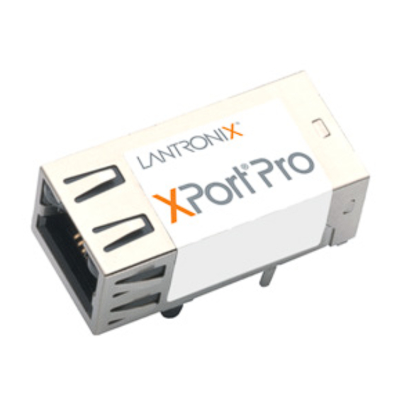
List of Figures Figure 2-1. Side View of the xPort Pro ____________________________________ 8 Figure 2-2. xPort Pro Block Diagram _____________________________________ 8 Figure 2-3. xPort Pro LEDs ___________________________________________ 10 Figure 2-4. Front View _______________________________________________ 11 Figure 2-5. Bottom View ______________________________________________ 11 Figure 2-6. -
Page 6: Introduction
1. Introduction About the Integration Guide This guide provides the information needed to integrate the Lantronix Port® Pro embedded device server into a customer printed circuit board. This manual is intended for engineers responsible for integrating the xPort Pro into their product. -
Page 7: Description And Specifications
The xPort Pro embedded device server is Lantronix’s most powerful, self-contained embedded networking module. Footprint compatible with the popular xPort product and running either Linux or the Lantronix Evolution OS® operating systems, the xPort Pro eliminates the complexity of designing network connectivity into a product and allows you to deploy advanced applications on the edge device itself. -
Page 8: Xport Pro Block Diagram
2: Description and Specifications The xPort Pro also contains the following: 3.3-volt serial interface All I/O pins are 3.3V tolerant Ethernet magnetics Power supply filters Reset circuit +1.5V regulator Crystals and Ethernet LEDs The xPort Pro requires +3.3-volt power and is designed to operate in an extended temperature range (see technical data). -
Page 9: Pcb Interface
2: Description and Specifications PCB Interface The xPort Pro has a serial port compatible with data rates up to 921600 bps. The serial signals (pins 4–8) are 3.3V CMOS logic level. The serial interface pins include +3.3V, ground, and reset. The serial signals connect to an internal UART driven at 3.3V. -
Page 10: Ethernet Interface
2: Description and Specifications Ethernet Interface The Ethernet interface magnetics, RJ45 connector, and Ethernet status LEDs are all in the device server shell. The xPort Pro PHY is Auto MDIX capable allowing connection to either straight through or cross over Ethernet cables. Table 2-3 Ethernet Interface Signals (Industry Standards) Signal Name Contact... -
Page 11: Dimensions
2: Description and Specifications Dimensions The xPort Pro dimensions are shown in the following drawings. Figure 2-4. Front View 18.25 [0.719] FRONT VIEW 16.25 [0.640] DIMS = mm (in) 11.55 [0.455] 7.15 [0.281] LEFT RIGHT CONTACT 8 CONTACT 1 14.50 [0.571] 4.03 [0.158] 5.85 [0.230] 13.50 [0.531]... -
Page 12: Recommended Pcb Layout
2: Description and Specifications Recommended PCB Layout The hole pattern and mounting dimensions for the xPort Pro device server are shown in the following drawing. For proper heat dissipation, it is recommended that the PCB have approximately 1 square inch of copper attached to the shield tabs. The shield tabs are an important source of heat sinking for the device. -
Page 13: Product Information Label
2: Description and Specifications Product Information Label The product information label contains important information about your specific unit, such as its product ID (name), bar code, part number, and Ethernet (MAC) add ress. Figure 2-8. Product Label Electrical Specifications Caution: Stressing the device above the rating listed in this table may cause permanent damage to the xPort Pro. -
Page 14: Functional Specifications
Metal shell, thermoplastic case Temperature Operating range: -40°C to +85°C (-40°F to 185°F) Shock/Vibration Non-operational shock: 500 g's Non-operational vibration: 20 g's Warranty Two year limited warranty Included Software Windows® 98/NT/2000/XP-based Lantronix® DeviceInstaller™ configuration xPort® Pro Embedded Device Server Integration Guide... - Page 15 2: Description and Specifications Category Description software and Windows®-based Com Port Redirector Regulatory Approvals Compliance FCC Part 15, Subpart B, Class B ICES-003 Issue 4 (2004), Class B EN55022:2006 and EN55024:1998 + A1:2001 + A2:2003 AS/NZS CISPR22:2006 ...
-
Page 16: A: Xport Pro 485 Connection Diagram
xPort Pro 485 Connection Diagram The following example illustrates a connection between the xPort Pro embedded device server and an external transceiver IC: xPort® Pro Embedded Device Server Integration Guide... -
Page 17: B: Compliance Information
EN61000-4-6 (Signal Port(s):3 V (Unmodulated R.M.S), 0.15 MHz - 80 MHz, 80% AM (1 kHz) EN61000-4-8 (50 Hz, 1.0 A/m (R.M.S.) RoHS, REACH and WEEE Compliance Statement Please visit http://www.lantronix.com/legal/rohs/ for Lantronix’s statement about RoHS, REACH and WEEE compliance. xPort® Pro Embedded Device Server Integration Guide...
Need help?
Do you have a question about the xPort Pro XPP1004000-02R and is the answer not in the manual?
Questions and answers