Honeywell 2000 Series Installation, Operation And Maintenance Manual
Herculine 2000 series
Hide thumbs
Also See for 2000 Series:
- User manual ,
- Operating manual (72 pages) ,
- Instructions for use manual (20 pages)

Related Manuals for Honeywell 2000 Series


Summary of Contents for Honeywell 2000 Series
- Page 1 ® HercuLine 2000 Series Actuator Installation, Operation and Maintenance Manual Doc. No.: 62-86-25-10 Revision: Date: 7/07 Honeywell Field Solutions...
- Page 2 However, we assume no responsibility for its use. While we provide application assistance personally, through our literature and the Honeywell web site, it is up to the customer to determine the suitability of the product in the application.
- Page 3 HercuLink™ User Manual 62-86-25-11 HART Communications Installation and Operations Manual 62-86-25-12 Contacts World Wide Web The following lists Honeywell’s World Wide Web sites that will be of interest to our customers. Honeywell Organization WWW Address (URL) Corporate http://www.honeywell.com Honeywell Process Solutions http://www.honeywell.com/ps...
- Page 4 Chassis Ground. Identifies a connection to the chassis or frame of the equipment shall be bonded to Protective Earth at the source of supply in accordance with national and local electrical code requirements. HercuLine™ 2000 Series Actuator - Installation, Operation and Maintenance Manual Revision 6 7/07...
-
Page 5: Table Of Contents
Master/Slave Arrangement......................26 Set Up and Calibration Procedures ..............31 Overview............................. 31 Local Display and Keypad......................31 Set Up Tips..........................33 Set Up Groups..........................34 Set Up Procedure ........................36 Revision 6 HercuLine™ 2000 Series Actuator - Installation, Operation and Maintenance Manual 7/07... -
Page 6: Contents
Position Sensor Operation ......................85 Remote Setpoint Operation......................85 Maintenance......................87 Introduction..........................87 Basic Maintenance ........................87 Spur Gear Lubrication ..........................87 Replacement Procedures......................89 Replacement/Upgrade/Accessory Kits ..............91 Replacement Kits ........................91 HercuLine™ 2000 Series Actuator - Installation, Operation and Maintenance Manual Revision 6 7/07... - Page 7 Contents Upgrade Kits..........................102 Accessory Kits .......................... 104 Troubleshooting ....................105 Introduction..........................105 Troubleshooting Procedures ....................106 ® Appendix A - HercuLine 2001/2002 Configuration Record Sheet....112 Index .........................116 Revision 6 HercuLine™ 2000 Series Actuator - Installation, Operation and Maintenance Manual 7/07...
- Page 8 Table 36 Motor Drive Fuse Replacment Procedure ....................89 Table 37 Relay PWA Replacement Procedure ......................90 Table 38 Replacement kits............................96 Table 39 Observable Symptoms of Failure ......................105 viii HercuLine™ 2000 Series Actuator - Installation, Operation and Maintenance Manual Revision 6 7/07...
- Page 9 Figure 43 Power Up Diagnostics ..........................108 Figure 44 Test Power Distribution PWA......................... 109 Figure 45 Test AUTO - MANUAL Switch ......................110 Figure 46 Test Relay Function ..........................111 Revision 6 HercuLine™ 2000 Series Actuator - Installation, Operation and Maintenance Manual 7/07...
-
Page 11: Introduction
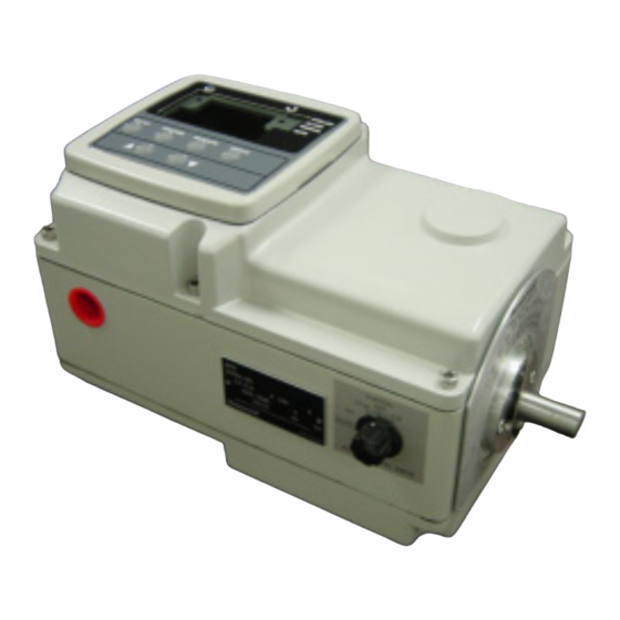
Model distinctions ® HercuLine 2000 series actuators are used in applications requiring on/off or power to open/close position proportional with 135 or 1000 ohm feedback. ® HercuLine 2001 and 2002 are smart actuators used in applications requiring current proportional control or digital control. - Page 12 Introduction Product Description Display and keypad Handwheel Conduit entry Shaft and position indicator Auto/manual switch ® Figure 1 HercuLine 2000 Series Actuator HercuLine™ 2000 Series Actuator - Installation, Operation and Maintenance Manual Revision 6 7/07...
-
Page 13: Figure 2 Herculine 2002 Actuator Internal View
External External Non-contact Non-contact auto-manual auto-manual sensor sensor Relay PWAs Relay PWAs switch switch ® Figure 2 HercuLine 2002 Actuator Internal View Revision 6 HercuLine™ 2000 Series Actuator - Installation, Operation and Maintenance Manual 7/07... - Page 14 Introduction Product Description HercuLine™ 2000 Series Actuator - Installation, Operation and Maintenance Manual Revision 6 7/07...
-
Page 15: Specifications
100 / (11.5) 15 / 25 36 / 60 200 / (22.5) 30 / 50 54 / 90 400 / (45.0) 45 / 75 400 / (45.0) Revision 6 HercuLine™ 2000 Series Actuator - Installation, Operation and Maintenance Manual 7/07... - Page 16 0 to 5 Vdc & 1 to 5 Vdc with 250 ohm resistor, (0 to 16 Vdc with 800 with 158 resistor) ohm resistor) Dual output 1000 ohms over 150 degrees (135 ohms with with 158 resistor) HercuLine™ 2000 Series Actuator - Installation, Operation and Maintenance Manual Revision 6 7/07...
- Page 17 Transient voltage protection provided. Control If input signal exceeds configured input range. Selectable and Failsafe operation adjustable. Field programmable Wire swap Direction of Rotation Continuous Duty Cycle Revision 6 HercuLine™ 2000 Series Actuator - Installation, Operation and Maintenance Manual 7/07...
- Page 18 Six single pushbutton keys allow access to all status displays and set up group Keys parameters. See Set Up and Calibration Procedures (page 31) for detailed information on display and keypad functions. HercuLine™ 2000 Series Actuator - Installation, Operation and Maintenance Manual Revision 6 7/07...
- Page 19 At least 8 MB Serial port with RS232 compatible levels to drive external converter Communications Note: As of this writing only Palm devices have this feature. Honeywell has qualified the M105, M125, M130, and M505 devices with the HercuLink application. Revision 6 HercuLine™...
-
Page 20: Model Selection Guide
Auxiliary Outputs No Auxiliary Switches 2 Auxilliary Switches 4 Auxilliary Switches Relay Outputs No Relays 2 Programmable Relay Outputs 2 Programmable Relay Outputs 4 Programmable Relay Outputs continued HercuLine™ 2000 Series Actuator - Installation, Operation and Maintenance Manual Revision 6 7/07... - Page 21 3. Requires PDA manufacturer's serial interface cable. 4. CSA approval is good for 75°C and a maximum relay load of 3.5 amps or 70°C with a relay load of 5 amps. Revision 6 HercuLine™ 2000 Series Actuator - Installation, Operation and Maintenance Manual 7/07...
-
Page 22: Installation
Installation Overview Installation Installation Overview ® The procedures to install the HercuLine 2000 Series actuator and place it in service require that you: • Select a suitable location for installation. (See Installation Considerations below.) • Mount the actuator securely. •... -
Page 23: Before Starting
If there are visible signs of damage to the shipping container, notify the carrier and Honeywell immediately. If there is no visible damage, compare the contents with the packing list. Notify the carrier and Honeywell immediately if there is equipment damage or shortage. -
Page 24: Figure 3 Outline And Dimensions Of Herculine 2000 Series Actuators
CLEARANCE FOR TOP REMOVAL: CLEARANCE FOR TOP REMOVAL: 101,6 101,6 11.379 11.379 25.4 25.4 1.00 1.00 inches ® Figure 3 Outline and Dimensions of HercuLine 2000 Series Actuators HercuLine™ 2000 Series Actuator - Installation, Operation and Maintenance Manual Revision 6 7/07... -
Page 25: Mechanical Installation
The actuator linkage can be set up to achieve an optimal delivered torque distribution for specific applications. To assist with linkage design, Honeywell offers a linkage analysis software application (HAL). The software can be ordered as P/N 51197910-001. -
Page 26: Figure 5 Variable Torque Linkage
Actuator Crank Arms ® The HercuLine 2000 Series Actuator comes standard with a crank arm with adjustable radius of 1.0 in (25.4mm) to 2.80 in (71.12mm). See Figure 6. Figure 6 Standard crank arm Figure 7 Crank arm with optional ball joint and push rod HercuLine™... -
Page 27: Electrical Installation
Do not run both the High Level and Low Level wiring through the same opening. The screw terminals, locations, and descriptions for all customer connections are identified in the tables and figures that follow. Revision 6 HercuLine™ 2000 Series Actuator - Installation, Operation and Maintenance Manual 7/07... -
Page 28: Herculine 2000 Terminal Connections
135 ohms potentiometer to 135 ohms REQUIRED ONLY IF AUTO/MANUAL REQUIRED ONLY IF AUTO/MANUAL SWITCH IS PRESENT SWITCH IS PRESENT ® Figure 8 HercuLine 2000 connections HercuLine™ 2000 Series Actuator - Installation, Operation and Maintenance Manual Revision 6 7/07... -
Page 29: Herculine 2001/2002 With Auto/Manual Terminal Connections
Brown Brown Brown Blue Blue Blue Black Black Black Black Wire Not Used Black Wire Not Used Black Wire Not Used ® Figure 9 HercuLine 2001/2002 connections Revision 6 HercuLine™ 2000 Series Actuator - Installation, Operation and Maintenance Manual 7/07... -
Page 30: Herculine 2003 Wiring Connections And Operation (Actionator 640D Replacement)
(in the same direction) for 180º or until the closing switch breaks. The motor stops in the closed position and completes one cycle. HercuLine™ 2000 Series Actuator - Installation, Operation and Maintenance Manual Revision 6... -
Page 31: Figure 11 Ce Wiring Part 1
Current input and output (slidewire emulation) connection • Communications and digital input connection Ground screw Current input and output (slidewire TB1-2 emulation) TB1-1 Communications and digital input Figure 11 CE wiring part 1 Revision 6 HercuLine™ 2000 Series Actuator - Installation, Operation and Maintenance Manual 7/07... -
Page 32: Figure 12 Ce Wiring Part 2
For voltage signal input, ensure jumper W2 on the CPU PWA is in the “Voltage” position. See Figure 27 on page 68. Observing polarity, connect the signal input wires to terminals TB3–4(+) and TB3–5(-) of the terminal block. HercuLine™ 2000 Series Actuator - Installation, Operation and Maintenance Manual Revision 6 7/07... -
Page 33: Burner Control/Flame Safety
Often, Gas Fired control applications use a Flame Safety System that drives the gas valve to full closed and full open during the start-up sequencefor the burner. HercuLine® 2000 Series actuators have been designed to be compatible with the Flame Safety Systems and to perform the required operations. -
Page 34: Series 90 Control - Herculine® 2001 Model Only
2. Due to variations in the definition of rotation directions, it may be necessary to reverse the action of the actuator from CCW to CW or vice versa. HercuLine™ 2000 Series Actuator - Installation, Operation and Maintenance Manual Revision 6... -
Page 35: Figure 15 T775 Controller Connections
Because of the mode of emulation of Series 90, it is likely that these connections will not work as intended. Instead, use the output or input limits which are programmable in the ® HercuLine 2001. Revision 6 HercuLine™ 2000 Series Actuator - Installation, Operation and Maintenance Manual 7/07... -
Page 36: Split Range
Signal failure is not a problem since the available failsafe settings allow you to set the actuator position on signal loss. HercuLine™ 2000 Series Actuator - Installation, Operation and Maintenance Manual Revision 6... -
Page 37: Figure 16 Flow Diagram
2 of the graph. Other relationships between units exist if the span adjustment (3) for ratio or if the zero adjustment is changed (1) for bias. Revision 6 HercuLine™ 2000 Series Actuator - Installation, Operation and Maintenance Manual 7/07... -
Page 38: Figure 18 Proportional Flow Using Multiple Actuators
120/240 Preferred 250 Ohms Ground 1 to 5 VDC Wiring ® ® NOTE: If using HART communications, for this application HART must be configured for Multi-drop operation. HercuLine™ 2000 Series Actuator - Installation, Operation and Maintenance Manual Revision 6 7/07... -
Page 39: Figure 19 Multiple Actuator Interconnection Diagrams
Ground Wiring = Voltage Figure 19 Multiple Actuator Interconnection Diagrams ® ® NOTE: If using HART communications, for this application HART must be configured for Multi-drop operation. Revision 6 HercuLine™ 2000 Series Actuator - Installation, Operation and Maintenance Manual 7/07... -
Page 40: Figure 20 Interconnection Diagrams
= Voltage 120/240 Neutral Alternate Ground Wiring Figure 20 Interconnection Diagrams ® ® NOTE: If using HART communications, for this application HART must be configured for Multi-drop operation. HercuLine™ 2000 Series Actuator - Installation, Operation and Maintenance Manual Revision 6 7/07... -
Page 41: Set Up And Calibration Procedures
STALLED ALARM Upper Display MANUAL (Four Characters) AUTO Lower Display (Six Characters) SET UP FUNCTION DISPLAY MAN/AUTO ® Figure 21 HercuLine 2000 Display and Keypad Revision 6 HercuLine™ 2000 Series Actuator - Installation, Operation and Maintenance Manual 7/07... -
Page 42: Table 6 Keypad Description
Indicates that the actuator has detected a motor stall condition. STALLED Indicates a programmed alarm condition exists. ☼ ALARM ☼ Indicates actuator is in manual mode MANUAL ☼ Indicates actuator is in automatic mode. AUTO HercuLine™ 2000 Series Actuator - Installation, Operation and Maintenance Manual Revision 6 7/07... -
Page 43: Set Up Tips
Set Up mode and display that was being used prior to entry into Set Up mode. Revision 6 HercuLine™ 2000 Series Actuator - Installation, Operation and Maintenance Manual 7/07... -
Page 44: Set Up Groups
Display operating and alarm status. Display self-test READ Table 20 diagnostic results. STATUS Display and/or set various parameters specific to the Table 21 actuator. DRVINF HercuLine™ 2000 Series Actuator - Installation, Operation and Maintenance Manual Revision 6 7/07... - Page 45 MAINT Use the display as an indicator, (in this case a Table 23 voltmeter) so you can verify that the position sensor is POSOUT operating properly. Revision 6 HercuLine™ 2000 Series Actuator - Installation, Operation and Maintenance Manual 7/07...
-
Page 46: Set Up Procedure
Stop at the function prompt that you want to change, and then proceed to the next step. HercuLine™ 2000 Series Actuator - Installation, Operation and Maintenance Manual Revision 6 7/07... - Page 47 If you do not press any keys for 30 seconds, the display times out and reverts to the mode and display shown prior to entering the set up mode. Revision 6 HercuLine™ 2000 Series Actuator - Installation, Operation and Maintenance Manual 7/07...
-
Page 48: Configuration Prompt Hierarchy
… … … DATSAV DATSAV DATSAV PASSWD PASSWD PASSWD MANRST MANRST MANRST LD CAL LD CAL LD CAL LD CFG LD CFG LD CFG RESTRT RESTRT RESTRT HercuLine™ 2000 Series Actuator - Installation, Operation and Maintenance Manual Revision 6 7/07... -
Page 49: Input Set Up Group
INPUT LOW RANGE VALUE in % is displayed. INP LO 0.0 to 90.0 NOTE: When Input Type (R_SP or S_90) is selected, Input default = 0.0 Hi is not configurable. Revision 6 HercuLine™ 2000 Series Actuator - Installation, Operation and Maintenance Manual 7/07... - Page 50 Selects the motor position you want the actuator to go to FsFVALH * when input signal is above the high end range value. default = 100 Range is from 0 to 100%. HercuLine™ 2000 Series Actuator - Installation, Operation and Maintenance Manual Revision 6 7/07...
- Page 51 = 1 - 20 Shaft Position Value— as a percentage of position range. Yn VAL 0 to 100 % Defaults are in increments of 5%. n = 1 - 20 Revision 6 HercuLine™ 2000 Series Actuator - Installation, Operation and Maintenance Manual 7/07...
-
Page 52: Equal Percentage Valve Characteristic
Order Equal Percentage Valve Characterization % of % of Range Range 10.7 13.2 15.7 18.7 22.6 27.2 33.4 53.8 Xn VAL - Actual Input 63.2 73.7 86.2 HercuLine™ 2000 Series Actuator - Installation, Operation and Maintenance Manual Revision 6 7/07... -
Page 53: Quick Opening Valve Characteristic
Table 12 Quick Opening Valve Characteristic Xn VAL Yn Val Order Quick Opening Valve Characteristic % of % of Range Range 97.5 Xn VAL - Actual Input 98.5 99.5 Revision 6 HercuLine™ 2000 Series Actuator - Installation, Operation and Maintenance Manual 7/07... -
Page 54: Relays Set Up Group
= 1, 2, 3, or 4 (in percent) NOTE: Relay Hysteresis parameter is accessible only if appropriate relay type is selected. n is the relay number, y is the relay contact. HercuLine™ 2000 Series Actuator - Installation, Operation and Maintenance Manual Revision 6 7/07... -
Page 55: Table 14 Relay Type Descriptions
The potentiometer or non-contact sensor output is out of range or has failed. Position Sensor Failure The digital input closure. Digital Input The total degrees traveled. Total Degrees Revision 6 HercuLine™ 2000 Series Actuator - Installation, Operation and Maintenance Manual 7/07... -
Page 56: Relay Examples
PosR R11VAL 80.0 R11HL RTYP12 PosR R12VAL 20.0 R12HL RLY1HY The figure below shows the resulting action. Motor 100% Position Open Closed Closed RELAY 1 Normally Open HercuLine™ 2000 Series Actuator - Installation, Operation and Maintenance Manual Revision 6 7/07... - Page 57 R11VAL 10.00 R11HL RTYP12 R12VAL -10.00 R12HL RLY1HY The resulting action is shown below. Input Motor 100% Position -10% +10% Closed Closed Open RELAY n Normally Open Revision 6 HercuLine™ 2000 Series Actuator - Installation, Operation and Maintenance Manual 7/07...
- Page 58 X10K R11VAL R11HL RTYP12 NONE The resulting action is that Relay 1 will trip when the number of accumulated motor starts in the maintenance group exceeds 200,000. HercuLine™ 2000 Series Actuator - Installation, Operation and Maintenance Manual Revision 6 7/07...
-
Page 59: Current Out Set Up Group
Note : If output type from model selection guide Slidewire Emulation CUROUT NONE No current output configured. Note : If output type from model selection guide None Revision 6 HercuLine™ 2000 Series Actuator - Installation, Operation and Maintenance Manual 7/07... -
Page 60: Communications Set Up Group
Floating Point Little Endian format — 3 2 1 0 FP L FPLB Floating Point Little Endian format with byte-swapped— 2 3 0 1 default = FP B HercuLine™ 2000 Series Actuator - Installation, Operation and Maintenance Manual Revision 6 7/07... -
Page 61: Digital Input Set Up Group
END POSITION VALUE — (DIGINP USER only) Selects the EndPos 0 – 100 (in percent) motor position you want the actuator to go to when digital input signal present (contact closure). Revision 6 HercuLine™ 2000 Series Actuator - Installation, Operation and Maintenance Manual 7/07... -
Page 62: Display Set Up Group
(Temperature in degrees C, Date format: ddmmyy) English — Display will show unit values in U.S. units. ENGL (Temperature in degrees F, Date format: mmddyy) default = ENGL HercuLine™ 2000 Series Actuator - Installation, Operation and Maintenance Manual Revision 6 7/07... -
Page 63: Lock Set Up Group
Disabled — Disables the front panel auto / manual switch functionality. ENAB Enabled — Enables the front panel auto / manual switch default = ENAB functionality. Revision 6 HercuLine™ 2000 Series Actuator - Installation, Operation and Maintenance Manual 7/07... -
Page 64: Set/Change Password
The adjustment will move one digit to the left. Press the key again and you will move one more digit to the left. HercuLine™ 2000 Series Actuator - Installation, Operation and Maintenance Manual Revision 6 7/07... -
Page 65: Read Status Set Up Group
CALIBRATION TEST DIAGNOSTIC — Read Only. Shows CALTST status of Calibration test diagnostic. Pass — Test passed, no errors PASS FAIL Fail— Test failed, see Troubleshooting (page 105) Revision 6 HercuLine™ 2000 Series Actuator - Installation, Operation and Maintenance Manual 7/07... -
Page 66: Drive Set Up Group
Up to 6 alphanumeric characters. See “Set Tag Name” on next page. MANUFACTURING DATE — Read Only. Displays date DMFG mmddyy * code of manufacture for actuator. ddmmyy HercuLine™ 2000 Series Actuator - Installation, Operation and Maintenance Manual Revision 6 7/07... - Page 67 Service to repair due to over-voltage damage Actuator reconfigured Warranty Repair * NOTE: Date format is set by the UNITS parameter. See SET DISPLA set up group. Revision 6 HercuLine™ 2000 Series Actuator - Installation, Operation and Maintenance Manual 7/07...
-
Page 68: Set Tag Name
Repeat for each character of the tag until the complete tag name is displayed. Press the FUNCTION key to go to the next parameter, or press DISPLAY to exit set up mode. HercuLine™ 2000 Series Actuator - Installation, Operation and Maintenance Manual Revision 6... -
Page 69: Maintenance Set Up Group
Multiply displayed value times 10 to get actual value. Range is 0 to 999,900,000. Revision 6 HercuLine™ 2000 Series Actuator - Installation, Operation and Maintenance Manual 7/07... - Page 70 = 1, 2, 3 or 4 cycle counter to zero. All — Resets all maintenance statistics to zero. SYST — Enables the system restart function. SYST default = NONE HercuLine™ 2000 Series Actuator - Installation, Operation and Maintenance Manual Revision 6 7/07...
- Page 71 † Note that the upper display contains the parameter name and the lower display contains the value. This is to allow for the display of hours: minutes: seconds. Revision 6 HercuLine™ 2000 Series Actuator - Installation, Operation and Maintenance Manual 7/07...
-
Page 72: Regions Of Motor Travel
Regio n of Trave l 30 o 60 o 150 o De gr ee s of R ot at io n Figure 23 Regions of Motor Travel HercuLine™ 2000 Series Actuator - Installation, Operation and Maintenance Manual Revision 6 7/07... -
Page 73: Cal Posout Group
Upper Display = Lower Display = CALPOS Upper Display = BEGN Lower Display = CALPOS FUNCTION Upper Display = (sensor output in volts) n.nnn Lower Display = POSOUT Revision 6 HercuLine™ 2000 Series Actuator - Installation, Operation and Maintenance Manual 7/07... -
Page 74: Auto - Manual Drive Switch
Actuator moves according to signal input and set up configuration. Actuator moves to the fully counterclockwise position. Actuator moves to the fully clockwise position. Actuator is idle. HercuLine™ 2000 Series Actuator - Installation, Operation and Maintenance Manual Revision 6 7/07... -
Page 75: Calibration
® Calibration of the HercuLine 2000 Series Actuator may consist of calibrating the motor circuit that positions the actuator with 0/4-20mA input signal, calibrating the potentiometer or non-contact sensor, and calibrating the slidewire emulation output or the 0/4-20mA output signal. Typically, only a motor calibration is required for installation. -
Page 76: Figure 25 Calibration Wiring Connections (Non-Slidewire Emulation)
Terminal Block Source Input Output Digital Voltmeter 250 ohm Internal 250 ohm resistor resistor settable through (supplied) Jumper W2 Current Voltage Figure 25 Calibration Wiring Connections (non-slidewire emulation) HercuLine™ 2000 Series Actuator - Installation, Operation and Maintenance Manual Revision 6 7/07... -
Page 77: Figure 26 Calibration Wiring Connections (Slidewire Emulation)
Signal Terminal Block Source Input Output Power Supply 1-18 VDC Internal 250 ohm resistor settable through Jumper W2 Current Voltage Figure 26 Calibration Wiring Connections (slidewire emulation) Revision 6 HercuLine™ 2000 Series Actuator - Installation, Operation and Maintenance Manual 7/07... -
Page 78: Figure 27 Jumper Location On Cpu Pwa
For an input calibration to be saved, you must complete the procedure. The calibration will not be saved if you exit without completing the steps of the procedure. To exit calibation mode, press DISPLAY or SETUP keys. HercuLine™ 2000 Series Actuator - Installation, Operation and Maintenance Manual Revision 6 7/07... -
Page 79: Table 25 Input Calibration Procedure
DISPLAY or SETUP keys. ATTENTION: When calibrating the motor to a short stroke range, you must reset the end-of-travel limit switches. See Setting End-of-Travel Limit Switches. Revision 6 HercuLine™ 2000 Series Actuator - Installation, Operation and Maintenance Manual 7/07... -
Page 80: Table 26 Motor Calibration Procedure
NOTE: The display will automatically go to the CAL CURENT set up display. See Table 27. You may also exit calibation mode by pressing the DISPLAY or SETUP keys. HercuLine™ 2000 Series Actuator - Installation, Operation and Maintenance Manual Revision 6 7/07... -
Page 81: Table 27 Output Calibration Procedure
Upper Display = Mode until you see Lower Display = CUR OUT FUNCTION Upper Display = Lower Display = CALOUT Upper Display = BEGN Lower Display = CALOUT Revision 6 HercuLine™ 2000 Series Actuator - Installation, Operation and Maintenance Manual 7/07... - Page 82 For a slidewire emulation output calibration to be saved, you must complete the procedure. The calibration will not be saved if you exit without completing the steps of the procedure. To exit calibration mode, press DISPLAY or SETUP keys. HercuLine™ 2000 Series Actuator - Installation, Operation and Maintenance Manual Revision 6 7/07...
-
Page 83: Table 28 Slidewire Emulation Calibration Procedure
Please note that performing this procedure will destroy any previously stored motor factory calibration values. Table 29 outlines the steps to perform a calibration to the position sensor circuit. Revision 6 HercuLine™ 2000 Series Actuator - Installation, Operation and Maintenance Manual 7/07... -
Page 84: Table 29 Ncs Position Sensor Calibration Procedure
Remove AC power to the actuator. Reinstall relay cards If present. Install a new gasket and replace extended cover. Secure to actuator with screws. Continue with calibration procedure in Table 31. HercuLine™ 2000 Series Actuator - Installation, Operation and Maintenance Manual Revision 6 7/07... -
Page 85: Figure 28 Location Of Ncs Assembly
NCS set screw NCS PWA Relay PWA card guides (relay PWAs removed) NCS Spoiler (shown at full 150 degree travel CCW) Figure 28 Location of NCS Assembly Revision 6 HercuLine™ 2000 Series Actuator - Installation, Operation and Maintenance Manual 7/07... -
Page 86: Table 30 Potentiometer Position Sensor Calibration Procedure
Remove AC power to the actuator. Reinstall relay cards If present. Install a new gasket and replace extended cover. Secure to actuator with screws. Continue with calibration procedure in Table 31. HercuLine™ 2000 Series Actuator - Installation, Operation and Maintenance Manual Revision 6 7/07... -
Page 87: Table 31 Load Position Sensor Factory Calibration
When calibrating the motor to a short stroke range, you must reset the end-of-travel limit switches. See Setting End-of-Travel Limit Switches. When motor calibration is complete, the calibration is now stored as the factory calibration of the actuator motor. Revision 6 HercuLine™ 2000 Series Actuator - Installation, Operation and Maintenance Manual 7/07... -
Page 88: Setting End-Of-Travel Limit Switches
If it becomes necessary to do adjust the limit switch cams in the field, use the procedure given in Table 32. While the unit is powered, a potentially lethal shock hazard exists inside the case. HercuLine™ 2000 Series Actuator - Installation, Operation and Maintenance Manual Revision 6... -
Page 89: Table 32 End-Of-Travel Limit Switch Setting Procedure
(using the auto/manual switch or by providing minimum and full input signal) and make sure the switches activate and turn off the motor. Revision 6 HercuLine™ 2000 Series Actuator - Installation, Operation and Maintenance Manual 7/07... -
Page 90: Figure 31 Location Of End-Of-Travel Limit And Auxiliary Switches
Aux switch #2 End of travel switch #2 Relay #4 Aux switch #3 (stops CCW rotation) Aux switch #4 Figure 31 Location of End-of-Travel Limit and Auxiliary Switches HercuLine™ 2000 Series Actuator - Installation, Operation and Maintenance Manual Revision 6 7/07... -
Page 91: Setting Auxiliary Switches
If it becomes necessary to do adjust the auxillary switch cams in the field, use the procedure given in Table While the unit is powered, a potentially lethal shock hazard exists inside the case. Revision 6 HercuLine™ 2000 Series Actuator - Installation, Operation and Maintenance Manual 7/07... -
Page 92: Table 33 Auxiliary Switch Setting Procedure
(using the auto/manual switch or by providing minimum and full input signal) and make sure the switches activate and turn off the motor. HercuLine™ 2000 Series Actuator - Installation, Operation and Maintenance Manual Revision 6... -
Page 93: Start-Up/Operation
- MANUAL positions. The output shaft should rotate in the direction indicated by the knob. The LED indicator on the local display should also indicate the actuator is in manual mode. Revision 6 HercuLine™ 2000 Series Actuator - Installation, Operation and Maintenance Manual 7/07... -
Page 94: Operating Displays
Note: A stall condition is not detected if a limit end of travel limit switch is activated while the motor is moving toward the setpoint, or if the motor position is within 0.5% of calibrated motor 0% and 100% end points.” HercuLine™ 2000 Series Actuator - Installation, Operation and Maintenance Manual Revision 6... -
Page 95: Position Sensor Operation
No input filtering is active on the input signal to the actuator. Revision 6 HercuLine™ 2000 Series Actuator - Installation, Operation and Maintenance Manual 7/07... -
Page 96: Figure 33 Terminal Block Connections For Modbus Communications
Start-Up/Operation Remote Setpoint Operation Actuator Terminal Block SHIELD DIGITAL INPUT COM M UNICATION Figure 33 Terminal Block Connections for Modbus Communications HercuLine™ 2000 Series Actuator - Installation, Operation and Maintenance Manual Revision 6 7/07... -
Page 97: Maintenance
Under normal operating conditions, the main worm gear should not require maintenance. Spur Gear Lubrication Honeywell recommends that during major shutdown periods the spur gears should be inspected and lubricated. Follow the steps in Table 35 to access the spur gear compartment and lubricate the gears if necessary. -
Page 98: Figure 34 Spur Gear Location
Maintenance Basic Maintenance Bottom cover Gears Idler spur gear Final output spur gear Motor pinion gear Figure 34 Spur Gear Location HercuLine™ 2000 Series Actuator - Installation, Operation and Maintenance Manual Revision 6 7/07... -
Page 99: Replacement Procedures
Remove power distribution PWA. Locate the two fuses on the power distribution PWA. See Figure 36. Carefully remove and replace fuse(s) with Wickmann T1 type 6A 250V, or equivalent (not available from Honeywell). Reinstall power distribution PWA. Reconnect connectors to CPU and power distribution PWA. -
Page 100: Table 37 Relay Pwa Replacement Procedure
Locking tabs on the card guides will engage to secure the PWA in place. Plug in wire connector to relay PWA. Install a new gasket if needed and replace cover. Secure to actuator with screws. HercuLine™ 2000 Series Actuator - Installation, Operation and Maintenance Manual Revision 6 7/07... -
Page 101: Replacement/Upgrade/Accessory Kits
To determine which kit you need, cross-reference Figure 37 through Figure 41 with Table 38 on page 96. Each kit contains replacement parts accessories and instructions for component replacement. Figure 37 Replacement Kits 6, 7, 8, 11, 12, 14 Revision 6 HercuLine™ 2000 Series Actuator - Installation, Operation and Maintenance Manual 7/07... -
Page 102: Figure 38 Replacement Kit 10
Replacement/Upgrade/Accessory Kits Replacement Kits Figure 38 Replacement Kit 10 HercuLine™ 2000 Series Actuator - Installation, Operation and Maintenance Manual Revision 6 7/07... -
Page 103: Figure 39 Replacement Kits 1, 2, 3, 4, 5, 9, 15, 16, 19
Replacement/Upgrade/Accessory Kits Replacement Kits 4,5,9 Figure 39 Replacement Kits 1, 2, 3, 4, 5, 9, 15, 16, 19 Revision 6 HercuLine™ 2000 Series Actuator - Installation, Operation and Maintenance Manual 7/07... -
Page 104: Figure 40 Replacement Kit 13
Replacement/Upgrade/Accessory Kits Replacement Kits Figure 40 Replacement Kit 13 HercuLine™ 2000 Series Actuator - Installation, Operation and Maintenance Manual Revision 6 7/07... -
Page 105: Figure 41 Replacement Kits 17, 18
Replacement/Upgrade/Accessory Kits Replacement Kits 17, 18 Figure 41 Replacement Kits 17, 18 Revision 6 HercuLine™ 2000 Series Actuator - Installation, Operation and Maintenance Manual 7/07... -
Page 106: Table 38 Replacement Kits
(HercuLine 2000) Pot 1 K Double 90 Degree #6-32 Hex Nut N #6 Washer #6 Lock Washer Machine Screw-Pan Hd-Cross Rec Top Cover Gasket Kit Instruction# 62-86-33-38 HercuLine™ 2000 Series Actuator - Installation, Operation and Maintenance Manual Revision 6 7/07... - Page 107 Kit Instruction# 62-86-33-40 Qty/Unit Part Number Description Figure ID # 515000657-502 Rvit-Z Ncs Replacement Kit Ncs, Rvit-Z Pwa 0-150 Machnl 4-40 X .31 Pnslstl Top Cover Gasket Revision 6 HercuLine™ 2000 Series Actuator - Installation, Operation and Maintenance Manual 7/07...
- Page 108 Split Washer M5 M3 X 5mm lg screw w/ext tooth lock washer Butt Splice (SA2000) Socket head cap screw-M5 x 12 Top Cover Gasket Kit Instruction# 62-86-33-36 HercuLine™ 2000 Series Actuator - Installation, Operation and Maintenance Manual Revision 6 7/07...
- Page 109 Figure ID # 51452443-503 Gasket Set Kit Bottom Cover Gasket Shaft Seal O-Ring 2.144 Id X 0.070 Buna N Top Cover Gasket O-Ring Buna N Display Gasket Revision 6 HercuLine™ 2000 Series Actuator - Installation, Operation and Maintenance Manual 7/07...
- Page 110 R/C Kit (Motor date codes prior to 8/5/2005) Capacitor, 2.25 Mfd Resistor, 200 Ohm,25w Capacitor, .75 Mfd, 400vac Resistor, 500 Ohm,25w Top Cover Gasket Bottom Cover Gasket Kit Instruction 62-86-33-44 HercuLine™ 2000 Series Actuator - Installation, Operation and Maintenance Manual Revision 6 7/07...
- Page 111 Qty/Unit Part Number Description Figure ID # 515000581-503 Auto/Manual Switch (replacement) Auto/Manual Label Nut, Sealing 3/8-32 Thrd Knob A/M Switch/Wire Assy Label, Customer Wiring, Top Cover Gasket Revision 6 HercuLine™ 2000 Series Actuator - Installation, Operation and Maintenance Manual 7/07...
-
Page 112: Upgrade Kits
Support plate-keypad Display PWA Top cover w/display no hndwhl Sems #4-40 x .310lg pnphstl Screw,metric panhd,cross rec Split washer Sleeve, keypad Display/keybd cable HercuLine 2001/2002 Top cover gasket HercuLine™ 2000 Series Actuator - Installation, Operation and Maintenance Manual Revision 6 7/07... - Page 113 Machine screw-pan hd-cross rec #6-32 hex nut N Stainless steel pin 3/32x4-40 setscrew sshxsocupsb Washer #6 Flat washer M4 (zinc) Resistor 158 ohms 1% 1/2W Kit Instruction# 62-86-33-39 Revision 6 HercuLine™ 2000 Series Actuator - Installation, Operation and Maintenance Manual 7/07...
-
Page 114: Accessory Kits
51452354-509 HercuLink software (PC/Palm) 51452354-510 Battery powered Palm/485 converter w/cables 51452174-501 Crank Arm - Standard 51452791-001 Crank Arm – 2003 Unit 51452352-501 Turk Cable for Communication Connection HercuLine™ 2000 Series Actuator - Installation, Operation and Maintenance Manual Revision 6 7/07... -
Page 115: Troubleshooting
Position sensor position is not correct. See page 85. Auto/Manual Switch does not operate correctly. See Figure 45 Relay(s) does not operate. See Figure 46 Revision 6 HercuLine™ 2000 Series Actuator - Installation, Operation and Maintenance Manual 7/07... -
Page 116: Troubleshooting Procedures
While the unit is powered, a potentially lethal shock hazard exists inside the case. Do not open the case while the unit is powered. Do not access the terminals while the unit is powered. HercuLine™ 2000 Series Actuator - Installation, Operation and Maintenance Manual Revision 6 7/07... -
Page 117: Figure 42 Test For Actuator Operation
RAMTST PASS SEETST PASS CALTST PASS CFGTST PASS Replace display All LEDs and assembly display segments light? Replace display assembly Figure 42 Test for Actuator Operation Revision 6 HercuLine™ 2000 Series Actuator - Installation, Operation and Maintenance Manual 7/07... -
Page 118: Figure 43 Power Up Diagnostics
CPU assembly. Do all LEDs and display segments light Replace display assembly. Figure 43 Power Up Diagnostics Test Non-Contact Sensor PWA See page 85. HercuLine™ 2000 Series Actuator - Installation, Operation and Maintenance Manual Revision 6 7/07... -
Page 119: Figure 44 Test Power Distribution Pwa
Pins 3, 4 to pin 7 Pins 5, 6 to pins 7, 8 24 V Pins 1, 2 to pins 7, 8 28 V + or – 3V Revision 6 HercuLine™ 2000 Series Actuator - Installation, Operation and Maintenance Manual 7/07... -
Page 120: Figure 45 Test Auto - Manual Switch
Power Supply PWA. (See D) c. Limit switches MANUAL d. Motor e. R/C networks f. etc.,Others? AUTO - MANUAL DRIVE Figure 45 Test AUTO - MANUAL Switch HercuLine™ 2000 Series Actuator - Installation, Operation and Maintenance Manual Revision 6 7/07... -
Page 121: Figure 46 Test Relay Function
Wire harness from Relay PWA to terminal block. See Relay replacement in Maintenance, Section 7. Figure 46 Test Relay Function Relay Associated Contacts RELAY1 RELAY2 RELAY3 RELAY4 Revision 6 HercuLine™ 2000 Series Actuator - Installation, Operation and Maintenance Manual 7/07... -
Page 122: Appendix A - Herculine 2001/2002 Configuration Record Sheet
X16 VAL - User configurable characterizer value __________________ 80.0 X17 VAL - User configurable characterizer value __________________ 85.0 X18 VAL - User configurable characterizer value __________________ 90.0 HercuLine™ 2000 Series Actuator - Installation, Operation and Maintenance Manual Revision 6 7/07... - Page 123 R21SCALE– Relay Scale __________________ RTYP22 – Relay Type __________________ NONE R22VAL – Relay Value __________________ R22HL– Relay High/Low __________________ R22SCALE– Relay Scale __________________ RLY2HY – Relay Hysteresis __________________ Revision 6 HercuLine™ 2000 Series Actuator - Installation, Operation and Maintenance Manual 7/07...
- Page 124 Read Only SEETST – Serial EEPROM Test Diagnostic __________________ Read Only CFGTST – Configuration Test Diagnostic __________________ Read Only CALTST – Calibration Test Diagnostic __________________ Read Only HercuLine™ 2000 Series Actuator - Installation, Operation and Maintenance Manual Revision 6 7/07...
- Page 125 LDCFG – Restore Factory Default Configuration __________________ RESTRT – System Restart __________________ NCSOUT – Non-contact sensor circuit output _________________ Read Only CAL NCSOUT Note 1: Type is set from model number. Revision 6 HercuLine™ 2000 Series Actuator - Installation, Operation and Maintenance Manual 7/07...
-
Page 126: Index
Crank Arms, 16 Input Low Range, 39 Customer Connections, 17 Input Set Up Group, 39 CW and CCW Direction. See Actuator Rotation Input Signal Connections, 22 Input Signals, 6 HercuLine™ 2000 Series Actuator - Installation, Operation and Maintenance Manual Revision 6 7/07... - Page 127 Relays, 44 Non-Contact Sensor Output Calibration, 72, 73 Slidewire Emulation, 23 Solid State Motor Control, 7 specifications, 5 Split Range, 26 Operating Temperature, 7 Spur Gear Lubrication, 87 Revision 6 HercuLine™ 2000 Series Actuator - Installation, Operation and Maintenance Manual 7/07...
- Page 128 Weight, 5 Technical and Operating Specifications, 5 Temperature Coefficient, 7 Terminal Connections, 18, 19 Total Degrees of Motor Travel Zero Suppression, 7 TOTDEG parameter, 59 Troubleshooting, 105 HercuLine™ 2000 Series Actuator - Installation, Operation and Maintenance Manual Revision 6 7/07...
- Page 129 Revision 6 HercuLine™ 2000 Series Actuator - Installation, Operation and Maintenance Manual 7/07...
- Page 130 Honeywell Process Solutions Industrial Measurement and Control 512 Virginia Drive Fort Washington, PA 19034 http://hpsweb.honeywell.com 62-86-25-10 0707 Printed in USA...
Need help?
Do you have a question about the 2000 Series and is the answer not in the manual?
Questions and answers