Advertisement
RM7890A,B/EC7890A,B
7800 SERIES Relay Modules
APPLICATION
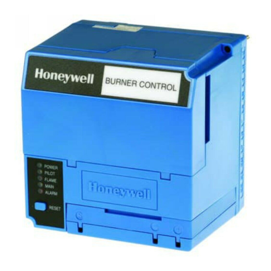
The Honeywell RM7890A,B,C/EC7890A,B Relay Modules
are microprocessor based integrated burner controls for
on/off automatically fired gas, oil, or combination fuel
single burner applications. The RM/EC7890 Relay Module
is intended to replace the RA890F,G, H Protectorelay®
Primary Control. The RM/EC7890 System consists of a
relay module, subbase, and amplifier. Options include: 2-
line VFD (see document 65-0090) or 4-line LCD (see
document 32-00110) Keyboard Display Module, and
remote display mounting.
Functions the RM/EC7890 provides include automatic
burner on/off sequencing, flame supervision, system
status indication, system or self-diagnostics and
troubleshooting.
This document provides installation and static checkout
instructions. Other applicable publications are:
Publication
No.
32-00110
S7800A2142 4-line LCD Keyboard Display
Module Product Data
32-0167
Q7800A/B Wiring Subbase Product Data
32-0166
204729A/C KDM NEMA4 Covers for 4-line
LCD KDM
65-0090
S7800A 2-line Keyboard Display Module
Product Data.
65-0091
S7810A Data ControlBus Module™ Product
Data.
65-0095
S7820 Remote Reset Module Product Data.
65-0097
221729C Dust Cover Packing Instructions.
65-0109
Flame Amplifiers for the 7800 SERIES
Product Data.
65-0131
221818A,C Extension Cable Assembly
Product Data.
65-0229
7800 SERIES Relay Modules Checkout and
Troubleshooting.
65-0249
S7810M ModBus Module.
SIL
Capable
Product
3
EC7890B1028, RM7890A1064,
RM7890B1055, RM7890A2064,
or RM7890B2055 only.
INSTALLATION INSTRUCTIONS
This document covers the following 7800 Series Relay
Modules:
1000-Series
• RM7890A1015
• RM7890A1031
• RM7890A1064
• RM7890B1014
• RM7890B1030
• RM7890B1055
• EC7890B1028
SPECIFICATIONS
Electrical Ratings (See Table 3):
Voltage and Frequency:
RM7890: 120 Vac (+10/-15%), 50/60 Hz (±10%).
EC7890: 220-240 Vac (+10%/-15%), 50/60 Hz (±10%).
Power Dissipation: 10W maximum.
Maximum Total Connected Load: 2000 VA.
Fusing Total Connected Load: 15A maximum, type SC
or equivalent, fast blow.
Environmental Ratings:
Ambient Temperature:
Operating: -40°F to +140°F (-40°C to +60°C).
Storage: -40°F to +150°F (-40°C to +66°C).
Humidity: 85% relative humidity continuous, noncon-
densing.
Vibration: 0.5G environment.
SIL 3 Capable
SIL 3 Capable in a properly designed Safety Instrumented
System. See form number 65-0312 for Certificate
Agreement.
2000-Series
• RM7890B2014
• RM7890A2015
• RM7890B2030
• RM7890A2031
• RM7890B2055
• RM7890A2064
32-00157-03
Advertisement
Table of Contents

Related Manuals for Honeywell 7800 Series


Summary of Contents for Honeywell 7800 Series
- Page 1 RM7890A,B/EC7890A,B 7800 SERIES Relay Modules INSTALLATION INSTRUCTIONS APPLICATION This document covers the following 7800 Series Relay Modules: The Honeywell RM7890A,B,C/EC7890A,B Relay Modules 1000-Series 2000-Series are microprocessor based integrated burner controls for • RM7890A1015 • RM7890B2014 on/off automatically fired gas, oil, or combination fuel •...
-
Page 2: Installation
RM7890A,B/EC7890A,B 7800 SERIES RELAY MODULES Approvals: 3. Installer must be a trained, experienced, flame RM7890A,B: safeguard service technician. Underwriters Laboratories Inc. Listed: File No. MP268. 4. After installation is complete, check out the product ANSI/UL 60730-2-5 / CSA C22.2 No. 60730-2-5 - operation as provided in these instructions. -
Page 3: Mounting Wiring Subbase
RM7890A,B/EC7890A,B 7800 SERIES RELAY MODULES Mounting Wiring Subbase Wiring 1. Mount the subbase in any position except horizon- tally with the bifurcated contacts pointing down. The WARNING standard vertical position is recommended. Any other position decreases the maximum ambient Electrical Shock Hazard. - Page 4 RM7890A,B/EC7890A,B 7800 SERIES RELAY MODULES 9. The KDM, or Data ControlBus Module™ (for remote termination across terminals 1 and 2 of the electrical mounting) must be wired in a daisy chain connectors for connections over 100 feet (31 configuration, meters).
- Page 5 RM7890A,B/EC7890A,B 7800 SERIES RELAY MODULES Table 3. Terminal Ratings. Terminal Number Description Ratings (RM7890A,B,C) Ratings (EC7890A,B) Flame Sensor Ground — — Earth G — — Earth Ground L2(N) Line Voltage Common — — Line Voltage Supply (L1) 120 Vac (+10%/-15%), 50 or 220-240 Vac (=10%/-15%), 50 or 60 Hz (±10%).
-
Page 6: Final Wiring Check
RM7890A,B/EC7890A,B 7800 SERIES RELAY MODULES Final Wiring Check Equipment Recommended 1. Voltmeter (1M ohm/volt minimum sensitivity) set on 1. Check the power supply circuit. The voltage and the 0 to 300 Vac scale. frequency tolerance must match those of the 2. - Page 7 RM7890A,B/EC7890A,B 7800 SERIES RELAY MODULES Table 5. Static Checkout. Test If Operation is Abnormal, Check the Items Test Jumpers Voltmeter Normal Operation Listed Below — 3-L2 Line Voltage. 1. Master switch. 2. Power connected to the master switch. 3. Overload protection (fuse, circuit breaker, etc.) has not opened the power line.
- Page 8 RM7890A,B/EC7890A,B 7800 SERIES RELAY MODULES Q7800 FOR DIRECT SPART IGNITION (OIL OR GAS) IGNITION TRANSFORMER (HOT) (L1) MAIN VALVE MASTER LINE VOLTAGE SWITCH ALARM BURNER CONTROLLER/LIMITS INTERMITTENT PILOT/IGNITION MAIN FUEL VALVE(S) IGNITION FLAME DETECTOR 4/10 SAFE- PFEP MFEP INITIATE STANDBY...
- Page 9 RM7890A,B/EC7890A,B 7800 SERIES RELAY MODULES Mounting RM/EC7890 Relay 3. Make sure no subbase wiring is projecting beyond the terminal blocks. Tuck in wiring against the back Module of the subbase so it does not interfere with the knife blade terminals or bifurcated contacts.
-
Page 10: Principal Technical Features
RM7890A,B/EC7890A,B 7800 SERIES RELAY MODULES PRINCIPAL TECHNICAL FEATURES The RM/EC7890 provides all customary flame safeguard When the tolerances are met, the INITIATE sequence functions as well as significant advancements in safety, restarts. If the condition is not corrected and the hold annunciation, and system diagnostics. -
Page 11: Settings And Adjustments
RM7890A,B/EC7890A,B 7800 SERIES RELAY MODULES SETTINGS AND Table 6. Site-Configurable Jumper Options. Jumper ADJUSTMENTS Number Description Intact Clipped Pilot Flame Selectable Site-Configurable Establishing Period (PFEP) seconds seconds Jumpers Flame Failure Action Lockout Relight The RM/EC7890 has two site-configurable jumper options, see Fig. 4 and Table 7. If necessary, clip the site-... - Page 12 RM7890A,B/EC7890A,B 7800 SERIES RELAY MODULES For More Information The Honeywell Thermal Solutions family of products includes Honeywell Combustion Safety, Eclipse, Exothermics, Hauck, Kromschröder and Maxon. To learn more about our products, visit ThermalSolutions.honeywell.com or contact your Honeywell Sales Engineer. Honeywell Process Solutions...
Need help?
Do you have a question about the 7800 Series and is the answer not in the manual?
Questions and answers