Table of Contents
Advertisement
Quick Links
Advertisement
Table of Contents

Related Manuals for AOR AR-ONE


Summary of Contents for AOR AR-ONE
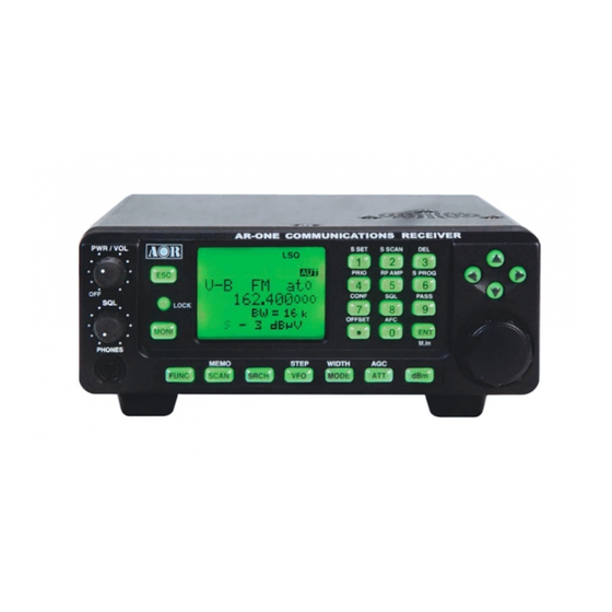
- Page 1 ® ® AR-ONE Ultra Wide Band Communications Receiver Operating manual AOR, LTD.
-
Page 2: Table Of Contents
1-5-2 Summary of keys ------------------------------------------------------------- 1-6 Computer control ------------------------------------------------------------- 1-7 IF output and Spectrum Display Unit (SDU5500, SDU5600) --------------------- 2 Getting Started ------------------------------------------------------------- 2-1 Making the AR-ONE ready for operation ----------------------------------------------- 2-1-1 LCD ------------------------------------------------------------- 2-1-2 Connect the antenna ------------------------------------------------------------ 2-1-3 Connect power -------------------------------------------------------------... - Page 3 2-4-1-1 Entering frequency using the numeric keypad ---------------------------- 2-4-1-2 Changing frequency using the main tuning dial --------------------------- 2-4-1-3 Changing frequency using UP arrow key or DOWN arrow key --------- 2-5 Changing receive mode -------------------------------------------------------------- 2-5-1 Auto mode selection ------------------------------------------------------------- 2-5-2 Receive mode selection ------------------------------------------------------------- 2-6 Changing tuning step size -------------------------------------------------------------...
- Page 4 4-3 Selecting a SCAN bank -------------------------------------------------------------- 4-4 Select SCAN ------------------------------------------------------------- 4-4-1 Adding select scan channels in memory read ------------------------------------ 4-4-2 Starting/Stopping select scan --------------------------------------------------------- 5 Search mode ------------------------------------------------------------- 5-1 Search type ------------------------------------------------------------- 5-1-1 Program search overview ------------------------------------------------------------- 5-2 Starting Program search ------------------------------------------------------------- 5-2-1 Reversing the direction of search ---------------------------------------------------...
- Page 5 --------------------------------------------------------- 6-16-1 Selecting IF output frequency -------------------------------------------------------- 6-17 Configure reference signal source -------------------------------------------------------- 7 Computer control ------------------------------------------------------- 7-1 How to send an RS-232C command ------------------------------------------------------- 7-2 Power on the AR-ONE ------------------------------------------------------ 7-3 Detailed RS-232C Command Listing of the AR-ONE ----------------------------------...
-
Page 6: Introduction
1-1 Introduction Thank you for purchasing the AR-ONE Ultra Wide Band Communications receiver. The AR-ONE is designed using the very latest technology to ensure the highest levels performance and reliability. To get the best possible results from your AR-ONE, we strongly recommend you to read this manual and familiarize yourself with the receiver. - Page 7 © This manual is protected by copyright AOR, LTD. 2003. No information contained in this manual may be copied or transferred by any means without the prior written consent of AOR, LTD. AOR and the AOR logo are trademarks of AOR, LTD. All other trademarks and names are acknowledged.
-
Page 8: Take Care Of Your Radio
Always keep the AR-ONE free from dust and moisture. Use a soft, dry cloth to gently wipe the set clean, never use abrasive cleaners or organic solvents which may damage certain parts. -
Page 9: Attention While Operating
4. Currently displayed VFO data is saved at power down (to increase speed of operation and to reduce write cycles). For this reason, if the AR-ONE is powered down using the PWR/VOL control or external power is removed, the last displayed frequency will be lost and the frequency used prior to this will be displayed when next powered up. - Page 10 & scan functions to operate. This is because the AR-ONE believes that it has found an active frequency when the squelch opens and “S” ‘squelch open’ icon is displayed to the left of the signal meter.
-
Page 11: Accessories Supplied
AC power supply (may be supplied in some world market areas and in a separate carton) DC power cable Operating manual (this booklet) 1-5 Controls & functions Controls are located on the front with most connectors on the rear of the AR-ONE, a brief identification is given here:... - Page 12 Front Panel 1. Volume control plus isolate power On/Off 2. Squelch control 3. Phones jack (3.5 mm mono or stereo may be used) 4. Escape key 5. Key Lock key 6. Monitor key 7. Function key 8. LCD (Liquid Crystal Display) 9.
- Page 13 The REMOTE RS-232C connector (16 & 17 above) is designed for connection directly to RS-232C serial port of a PC. By daisy chain of the units, you can control up to 99 AR-ONE with one PC. No interface is required, just a standard RS-232C straight cable. Connections...
-
Page 14: Keypad
LOCK This key is intentionally small to reduce the chances of accidental operation. Key lock is useful when you do not wish an important frequency to be lost or the AR-ONE to be incorrectly set to a different frequency. The monitor key is used to force the squelch open so that you may manually intervene to ensure that no weak signals are missed. - Page 15 Push this key to select VFO mode. There are 10 VFOs (VFO-A through VFO-J) with the AR-ONE. STEP Push the [FUNC] key, and then push to select the desired frequency step. MODE Push this key to select the desired receive mode.
- Page 16 S.SCAN Push the [FUNC] key, and then push this key to initiate SELECT SCAN. Push the [FUNC] key, and then push this key to delete the memory channel, search bank, and pass frequency. PRIO Push the [FUNC] key, and then push this key to initiate PRIORITY CHANNEL RECEIVE. RF AMP Push the [FUNC] key, and then push this key to activate/deactivate the RF amplifier function (ON/OFF/AUTO).
-
Page 17: Computer Control
Computer control Connect the AR-ONE to the serial port of a computer using an RS-232C serial cable terminated in a 9-pin male connector. The RS-232C parameters may be defined using the CONFIG menu. Baud rates (transfer speed) set to either 4800 or 9600 bps. Since there are two independent RS-232C port with the AR-ONE, it is possible to set an ‘address’... -
Page 18: Connect The Antenna
A receive frequency range of the SA7000 is 30 KHz ~ 2000 MHz. 2-1-3 Connect power Connect the power to the DC power jack on the rear panel of the AR-ONE. Use either a supplied AC power adapter. Or a regulated DC power supply (12 ~ 14 V with capacity 2A) may be used. -
Page 19: Squelch Circuit
6. To select NOISE SQUELCH, repeat above steps. 2-4 VFO selection The AR-ONE has ten (10) VFOs being identified as “V-A” through “V-J” on the top left of LCD. The term VFO historically means ‘Variable Frequency Oscillator’ and today refers a tuneable data store which contains frequency, step, step-adjust, attenuator etc. -
Page 20: Tuning Frequency
step are automatically selected. 2-4-1 Tuning frequency 2-4-1-1 Entering a frequency using the numeric keypad While in VFO mode, enter the required frequency using MHz format followed by the ENT key. Example of frequency entry of 80.8 MHz Push the [8] key. Push the [0] key. Push the [.] key. Push the [8] key. Push the [ENT] key. Example of frequency entry of 954 KHz (0.954 MHz) Push the [.] key. -
Page 21: Changing Receive Mode
For your convenience, receive mode and tuning step size have been pre-programmed into the AR-ONE auto-mode band plan data at the factory to simplify operation of the receiver, especially while you familiarize yourself with all functions. Should you wish, the defaults be manually overridden at anytime so that you may select an alternative receive mode and tuning step on any frequency. -
Page 22: Auto Mode Selection
Used only for local services such as VHF band stereo (received as mono on the AR-ONE) and UHF TV sound channels. LSB – Lower Side Band – is form of SSB (Single Side Band). LSB tends not to be used commercially but is extensively used by Radio Amateurs on frequencies below 10 MHz. -
Page 23: Receive Mode Selection
When auto-mode is in operation, receive mode and tuning step size are automatically selected for you by the AR-ONE microprocessor. To activate auto-mode or reconfirm its selection while in VFO mode, Push and hold the MODE key for more than 2 seconds. -
Page 24: If Bandwidth
VFO key. The third row of the LCD will display the current default size. The bottom line of the LCD displays the icon “STEP SET” to indicate that the AR-ONE is waiting you to change the step size. Use the main tuning dial or arrow key to select the desired step size. To accept the displayed tuning step size, push the ENT key. -
Page 25: Manually Selecting If Bandwidth
air. However, it is not simply a case of using the narrowest filter at all times, particular modes require differing amounts of bandwidth in order to operate otherwise the receive system simply will not produce intelligible sound. Correct receive mode and IF bandwidth must always be selected for optimum reception. If the bandwidth selection is too narrow, distortion or signal break-up may occur. -
Page 26: Agc (Automatic Gain Control)
2-8 AGC (Automatic Gain Control) To change the AGC parameter setting, push the FUNC key and then push the ATT key. Selecting a new AGC parameter from the list of MANU, FAST, MID, SLOW by rotating the main tuning dial or arrow key. To accept the new AGC parameter, push the ENT key. When MANU is selected, a desired parameter can be entered between 0 ~ 255 in the Configuration Menu. -
Page 27: Rf Amplifier
When ATT is set to 10 dB, the ‘t1’ icon will display on top right of the LCD, When ATT is set to 20 dB, the ‘t2’ icon will display on top right of the LCD. 2-10 RF AMPLIFIER The AR-ONE features a preamplifier. The LCD icon “a” is used to display the setting in use. -
Page 28: Offset
To change the RF Amplifier setting, push the FUNC key and then push the 5 key. Selecting a new AMP parameter from the list of ON, OFF, AUTO by rotating the main tuning dial or arrow key. To accept the new AMP parameter, push the ENT key. 2-11 OFFSET This function enables receive frequency to be quickly SHIFTED by a predetermined values, this makes it easy to track duplex-transmissions or check repeater inputs/outputs. -
Page 29: Using Pre-Programmed Frequency Offset Data
use, it may appear rather long winged to toggle on/off in VFO mode. However even when programmed, frequency offset is in no way detrimental to normal operation. The acceptable range of frequency offset is 0 MHz to 999.999 MHz, of course if the offset is set to 0 MHz, the frequency will not change! Before the FREQUENCY OFFSET function be used, it first needs to be configured (unless factory programmed for certain bands). -
Page 30: Memory Channels And Banks
Think of memory channels as pages in a notebook each of which is numbered to identify it. Data may be written to each new page (memory channel) and each page may be overwritten with new data, they can be used over and over again. The AR-ONE has 1,000 memory channels and a priority channel. - Page 31 Examples are “000” for the first channel location in memory bank “0” and “099” for the last memory channel in memory bank “0”. “415” is the location: memory bank “4” channel “15”. The data contents of memory and search banks are held in a EEPROM so that no backup battery is required for memory retention.
- Page 32 1) Start by selecting VFO mode then key in the frequency of 123.500 MHz, “mode and step size” are set to the default auto mode. Push the VFO key to set the AR-ONE into VFO mode. Push the 1 key. Push the 2 key.
-
Page 33: Memory Read "M.rd
Push the FUNC key and the push the SCAN key to go into memory read mode, the “M.RD” icon appears on the top left of the LCD to confirm operation. The AR-ONE will monitor whatever memory channel you enter memory read. -
Page 34: Deleting Memory Channels
Push the ENT key to delete it or push ESC to abort. 4 SCAN – scanning memory channels The AR-ONE has a SCAN mode whereby the contents stored in the MEMORY CHANNELS ARE AUTOMATICALLY RECALLED AND MONITORED very quickly for activity –... -
Page 35: Scan - Outline Introduction
During SCAN, the AR-ONE automatically recalls memory channel which contains data in numeric order and monitors it looking for activity. When an ‘active’ memory channel is located (when a signal is found and the squelch is open), the AR-ONE will temporarily stop scanning. -
Page 36: Select Scan
To exit from SCAN mode, push the VFO key. 4-4 Select scan Select scan enables you to ‘tag’ memory channels to make a temporary list up to 50 channels in the same memory bank for scanning in a separate list called the SELECT SCAN LIST. -
Page 37: Search Mode
To stop select scan, push the VFO key. Search mode In search mode, the AR-ONE is programmed to automatically tune between two specified frequency limits looking for activity. Please refer to section 1-3 of this manual if you do not fully understand the function of SEARCH. -
Page 38: Starting Program Search
LO (lower) start frequency HI (upper) stop frequency Receive mode (or set to AUTO MODE) Text comment The program search banks are identified by numbers (01 ~ 40). To help with identification, each bank may be labeled with an alphanumeric text comment. 5-2 Staring program search Presuming that data is already stored into a search bank …... -
Page 39: Reversing The Direction Of Search
5-2-2 Forcing the search to resume If the AR-ONE stops on an unwanted busy frequency, rotate the main tuning dial knob or use the up arrow key or down arrow key to force the search process to resume from the current frequency displayed. -
Page 40: Programming A Search Bank
5-4 Programming a search bank Each of the 40 search banks may be programmed with different frequency limits, receive modes, etc. as listed in section 8-1-1 of this manual. Push the FUNC key, and then push the 6 key to access the “SRCH PROG” menu. Use the main tuning dial, or the right arrow key or the left arrow key or keypad to select the bank you wish to program or overwrite. - Page 41 Push the down arrow key. Input the lower start frequency in MHz format (don’t push the ENT key).
- Page 42 Push the down arrow key. Input the higher end (stop) frequency in MHz format (don’t push the ENT key). Push the down arrow key.
- Page 43 MODE SET Use the right arrow key or left arrow key or main tuning dial to select receive mode, the SET key is used as a short cut to “AUTO”. Note: If the receive mode is set to “AUTO”, the receive mode, channel step will be taken from the pre-programmed auto band plan data, for this reason the detailing will not be required while programming so is kipped….
- Page 44 STEP Assuming that a receive mode other than “AUTO” was selected, you will be presented with the “STEP SET” menu. Use the main tuning dial or the right arrow key or left arrow key to select the required tuning step from the following: 0.001 (1Hz), 0.010 (10Hz), 0.500 (500Hz),...
-
Page 45: Deleting Search Banks
To accept the data input, push the ENT key. 5-5 Deleting search banks A delete menu is provided so that you can delete program search data (of course you may simply overwrite the data, too) . While in search mode, the DELETE menu is accessed using the key sequence. Push the FUNC key and then push the 3 key. -
Page 46: Locking Out Unwanted Active Frequencies (Pass)
Using the main tuning dial, keypad, right arrow key or left arrow key, select the desired search bank. The “HI” and “LO” frequency limits will appear on the LCD along with any associated text comment to aid the identification of the required search bank. To delete the program search bank, push the ENT key. -
Page 47: Deleting Pass Channels
It is possible to lock out (PASS) unwanted frequencies while is program search mode. This is useful to eliminate unwanted permanent transmissions. It is important to understand the PASS function before taking action or transmissions may be missed. While stopped on unwanted frequency, push the FUNC and then push the 9 key. The search process will resume. - Page 48 If pass channels have already been tagged for the current search bank, the icon “PAS” (PASS) will be displayed on the LCD. Push the FUNC key to delete the pass frequency. To exit from this menu, push the ENT key.
-
Page 49: Configuration Menu
6 Configuration menu The configuration menu is used to set fundamental operating parameters and other variables which do not appear in any menu heading. BEEP Confirmation & error tone LAMP LCD& keypad illumination DIMM Backlit illumination dimmer CONTRAST LCD contrast adjustment OPENING MESSAGE Change the power-up message AGC (Automatic Gain Control) adjustment... -
Page 50: Configure Beep
Auto/THRU/25uS/75uS/750uS AUTO 6-1 Configure beep The AR-ONE emits confirmation ‘beeps’ while the keypad is used. A ‘HIGH’ pitched beep indicates correct operation while a ‘LOW’ pitched beep indicates that an error or unexpected entry has taken place. The volume of the beep is independent of the main volume control and can be separately defined. -
Page 51: Configure Lamp
Or, push the down arrow key to move to the next item on the configuration menu (LAMP). 6-2 Configure lamp The AR-ONE is equipped with high intensity green LEDs to illuminate the LCD and keypad when operating in areas of low level lighting. -
Page 52: Configure Contrast
Or, push the down arrow key to move to the next item on the configuration menu (CONTRAST). 6-4 Configure contrast The AR-ONE is equipped with variable LCD contrast which is adjustable in 32 steps to provide best visibility under different viewing angles, extremes of ambient light & temperature (and between sets due to variation). -
Page 53: Configure If-Gain (Intermediate Frequency Gain)
The manual AGC function is to adjust the receiver’s AGC (Automatic Gain Control) when it is set OFF. The default setting for Manual AGC is 255, maximum gain control value. The value can be adjusted according to the receiving condition. To access the configuration menu, push the FUNC key and then push the 7 key. -
Page 54: Configure Rf-Gain (Radio Frequency Gain)
The IF gain control reduces the amplification in the receiver’s IF circuits and has the effect reducing the sensitivity of the receiver. Normally, this is performed by the AGC system, and the control is left at maximum gain, but reducing the gain can be useful to limit noise when listening to CW or SSB signals. -
Page 55: Configure Remote Bps (Baud Rate)
Or, push the down arrow key to move to the next item on the configuration menu (RMT-ID). 6-9 Configure RMT-ID (Remote ID) When multiple units are connected via remote connectors, each AR-ONE must be assigned a different ID (address). The value is adjustable between 00 ~ 99. The default value is 00. -
Page 56: Configure Delay (Scan Delay And Search Delay)
Or, push the down arrow key to move to the next item on the configuration menu (DELAY). 6-10 Configure DELAY (Scan delay and Search delay) This parameter affects the time, the AR-ONE will remain on active frequency in scan mode or search mode once the received signal has disappeared and the squelch has closed. This Is particularly useful for customizing how long the receiver will wait for a reply before resuming scan or search. -
Page 57: Free (Scan Free And Search Free)
This is useful if you wish to gain a snap shot of activity without the AR-ONE being tied to a busy frequency for long periods of time (such as when monitoring active commercial repeaters etc). -
Page 58: Configure Speaker
(SPEAKER). 6-12 Configure SPEAKER The AR-ONE is equipped with 2 separate speakers, one is in the main receiver unit and the another one is in the control head (Note: This function is available only when an optional separation kit is used), and a phones jack. Each speaker / head phones output can be configured under this menu. -
Page 59: Configure Headphones Output
Or, push the down arrow key to move to the next item on the configuration menu (Audio Filter). 6-13 Configure audio filters (HPF / LPF) The AR-ONE is equipped with an audio HPF (High Pass Filter) and a LPF (Low Pass Filter). 6-13-1 Configure audio HPF (high pass filter) - Page 60 There are four available pass frequencies: 50Hz, 200Hz, 300Hz, and 400Hz. The higher the frequency the more limited the audio bandwidth. For highest fidelity for listening, select 50Hz. The filter selection can be set to automode to select the proper filter setting automatically.
-
Page 61: Configure Audio Lpf (Low Pass Filter)
pass filter setting (AUTO / 50Hz / 200Hz / 300 Hz or 400Hz). Push the ENT key to accept the data and return to a standard display. Alternatively, push the ESC key to abort entry. Or, push the down arrow key to move to the next item on the configuration menu (LPF). 6-13-2 Configure audio LPF (low pass filter) The audio low pass filter is useful to cut off high tones (allowing low tones to pass) to improve intelligibility of weak signals in close proximity to adjacent interference and to... -
Page 62: Configure Prio-Ch (Priority Channel)
The priority checking is accomplished by momentarily tuning the receive circuit to the priority frequency to see if it is active. If the activity is found, the AR-ONE will remain on the active frequency until the signal disappears. If no activity is detected, the receiver returns to the VFO frequency, scan channel or search bank from where it originated. - Page 63 keeping an eye on a distress frequency while scanning or searching another frequency band. Note: Depending upon the frequency and mode stored as priority, an audible click may be heard when the priority function is in operation. This is quite normal and is caused by the internal switching of circuitry necessary to accomplish the frequency change (as two frequencies cannot simultaneously be monitored).
-
Page 64: Configure If Output Frequency
Or, push the down arrow key to move to the next item on the configuration menu (IF output). 6-16 Configure IF output frequency The function enables you to tap the 2 IF signal (10.7MHz) or the 3 IF signal (455KHz) from the BNC (marked as 10.7MHz) type connector on the rear panel. -
Page 65: Computer Control
This completes the configuration settings. Computer control Connect the AR-ONE to one of the serial port of a computer using an RS-232C cable terminated in a 9-pin plug. The RS-232C parameters may be defined using the OCNFIGURATION menu. Baud rates (data transfer speed) may be set to 4800 or 9600 bps. -
Page 66: Power On The Ar-One
RS-232C baud rate. 7-2 Power on the AR-ONE Connect an RS-232C cable between the AR-ONE and a PC, type any key to power up the AR-ONE. 7-3 Detailed RS-232C command listing of the AR-ONE... - Page 67 To read: RX <CR> Response: Memory manual mode MR MXmnn RFnnnnnnnnnn STnnnnnn Aun MDn BWn ATn AMn TMxxxxxxxx Memory scan mode MS MXmnn RFnnnnnnnnnn STnnnnnn Aun MDn BWn ATn Amn TMxxxxxxxx Memory select mode SM MXmnn RFnnnnnnnnnn STnnnnnn Aun MDn BWn Atn Amn TMxxxxxxxx Search mode SSmm RFnnnnnnnnnn STnnnnnn Aun MDn BWn Atn Amn...
- Page 68 To read: AU <CR> Response: 7-3-5 OPERATION MODE (n: 0 - 6) Auto mode will be disabled by this command FM (BW=16KHz,HPF=50Hz,LPF=3KHz,De-emphasis=750uS) AM (BW=6KHz, HPF=50Hz, LPF=3KHz, De-emphasis=THRU) CW (BW=0.5KHz, HPF=50Hz, LPF=3KHz, De-emphasis=THRU) (BW=3KHz, HPF=50Hz, LPF=3KHz, De-emphasis=THRU) (BW=3KHz, HPF=50Hz, LPF=3KHz, De-emphasis=THRU) WFM (BW=200KHz, HPF=50Hz, LPF=12KHz, De-emphasis=75uS) NFM (BW=8.5KHz, HPF=50Hz, LPF=3KHz, De-emphasis=750uS) To read: MD <CR>...
- Page 69 400Hz AUTO To read: HP <CR> Response: 7-3-8 LPF (Low Pass Filter) (n: 0 – 3 & F) Auto mode will be disabled by this command 3KHz 4KHz 6KHz 12KHz AUTO To read: LP <CR> Response: 7-3-9 AGC (Automatic Gain Control) (n: 0 –...
- Page 70 7-3-11 RF ATT (Attenuator) (n: 0 –3) 10dB 20dB AUTO To read: AT <CR> Response: 7-3-12 RF AMP (Amplifier) (n: 0 – 2) RF AMP OFF RF AMP ON RF AMP AUTO To read: AM <CR> Response: 7-3-13 BFO FREQ (Beat Frequency Oscillator Frequency) BF +/-nnnn (nnnn: 0000 - +/- 3000Hz) Available in CW, LSB, USB mode only...
- Page 71 7-3-16 AF GAIN AGnnn (nnn: 000 –255) Default: 255 Note: The volume control knob must be turned fully counterclockwise To read: AG <CR> Response: AG nnn 7-3-17 MANUAL GAIN (10.7 MHz AGC) MGnnn (nnn: 000 – 255) Default: 255 Note: Available only when the AGC is set to OFF To read: MG <CR>...
- Page 72 To read: LM <CR> Response NSQm LMnnn --- When the noise squelch is selected (nnn: 000 – 999) LSQm LMnnn --- When the level squelch is selected (nnn: 000 – 999) m: 1 when the squelch is closed m: 0 when the squelch is opened 7-3-22 AUTO SIGNAL LEVEL (n: 0 or 1)
- Page 73 (n: 0 or 1) Available when LA is set to 2 (Auto). n: 0 BACKLIT OFF n: 1 BACKLIT ON (Default) To read: BL<CR> Response: 7-3-25 BACKLIT DIMMER (n: 0 or 1) n: 0 NORMAL (Default) n: 1 DIMM To read: LD<CR> Response: 7-3-26 LCD CONTRAST LVnn...
- Page 74 n: 1 To read: PO<CR> Response: 7-3-30 DELAY TIME (SCAN DELAY AND SEARCH DELAY) DDn.n (n.n: 0.0 – 9.9 second) Default: 2.0 sec. (hold) To read: DD<CR> Response: DDn.n DDFF 7-3-31 FREE SCAN SPn.n (n.n: 0.0 – 9.9 second) n.n : 0.0 FREE SCAN OFF (Default) n.n: 0.1 –...
- Page 75 To read: OL<CR> Response: OLmm nnnnnnnnnn (10 digit) 7-3-35 SIGNAL LEVEL UNIT (in dBuV) – Read only LU nnn (-nnn – nnn) dBuV To read: LU<CR> Response: LU nnn 7-3-36 SIGNAL LEVEL UNIT (in dBm) – Read only LB nnn (-nnn –...
- Page 76 Read search data of the current search bank SRnn (nn: 01 – 40) Search data in search bank 1 - 40 (n: 1 - 10) 4 Search data in search bank 1- 10 Search data in all search bank SRn SLnnnnnnnnnn Sunnnnnnnnnn AUn MDn BWn ATn AMn TTxxxxxxxx SRn --- (Blank) 7-3-39 PASS FREQUENCY –...
- Page 77 QS%% Delete all search data and pass frequencies on all search banks 7-3-43 TRANSFER THE CURRENT SEARCH DATA TO VFO – Write only (n: 0 – 9) n: 0 VFO – A n: 1 VFO – B VFO – J (Default) 7-3-44 MEMORY DATA SETTING –...
- Page 78 n: 0 n: 1 To read: GA<CR> Response: 7-3-47 SELECT MEMORY LIST – Read only GRnn (nn: 00 – 99) Memory channel on the designated bank GR%% All channels (100channels maximum) (n: 0 – 9 ) List of 10 channels data Next 10 channels data [Example]: GRnn mxx …...
-
Page 79: Specifications
8 SPECIFICATIONS Model: AR-ONE Configuration: Triple conversion super heterodyne Frequency coverage: 10 KHz ~ 3.3 GHz (no gap) Receive mode: AM, NFM, WFM, USB, LSB, CW, DATA Sensitivity: (AM mode – 10 dB S/N, NFM mode – 12 dB SINAD,... - Page 80 10 ~ 40 KHz: CW 22.3 uV 40 ~ 100 KHz: AM – 4.5 uV, CW – 1.5 uV 100 KHz ~ 40 MHz: AM 2.5 uV, 2 ~ 40 MHz: AM – 1.5 uV, SSB/CW – 0.7 uV, NFM – 0.89 uV 40 MHz ~ 1 GHz: AM –...
-
Page 81: Optional Accessories
AOR USA, Inc. (AOR) warrants its receivers as described below: AOR will repair or exchange equipment as a result of defects in parts or workmanship for a period of one year from the date of original retail purchase from an authorized AOR dealer. - Page 82 Any and all implied warranties, including those pertaining to merchantability and utility for a specific purpose are limited to the duration of this limited warranty. AOR’s limits on warranty pertain only to the repair or, at its option, replacement of defective products. AOR shall not be liable for any other damages, including consequential, incidental or otherwise, arising from any defect.
- Page 83 If you have questions about this limited warranty, or the operation of your AOR product, contact AOR at (310) 787-8615 during normal business hours (9 am ~ 5 pm Pacific Time Zone), or write to AOR, 20655 S. Western Ave., Suite 112, Torrance, CA 90501. You may also send a fax to AOR at (310) 787-8619.
- Page 84 Manufacturer: AOR, LTD. 2-6-4, Misuji, Taito-Ku, Tokyo, 111-0055, Japan URL: www.aorja.com e-mail: post@aorja.com US distributor: AOR USA, INC. 20655 S. Western Ave. Suite 112 Torrance, CA 90501 Phone: 310-787-8615 Fax: 310-787-8619 URL: www.aorusa.com e-mail: info@aorusa.com...
Need help?
Do you have a question about the AR-ONE and is the answer not in the manual?
Questions and answers