AOR AR2300 Operating Manual
Black-box receiver
Hide thumbs
Also See for AR2300:
- Operating manual (67 pages) ,
- Operating manual (60 pages) ,
- Operating manual (67 pages)

Related Manuals for AOR AR2300


Summary of Contents for AOR AR2300
- Page 1 AR2300 BLACK-BOX RECEIVER OPERATING MANUAL OCTOBER 28, 2020 AOR, LTD. www.aorja.com...
- Page 3 INTRODUCTION Thank you for purchasing the AR2300. AR2300 is a high-end black-box type receiver with wide band coverage between 40kHz and 3.15GHz. Some of its outstanding features are: 1) Digital signal processing: Input signals after the 45.05MHz IF are converted from analog to digital by a DSP processor. There is no AGC in the analog processing unit, as all processing, including AGC, is done by DSP.
- Page 4 Turn OFF the receiver’s power and / or disconnect the DC power cable when you will not use the receiver for a long period of time. The AR2300 may receive its own oscillated frequency, resulting in no reception or only noise reception including on the spectrum displayed by control software, on some frequencies.
-
Page 5: Table Of Contents
Database window description ....................13 4.4.5 Description of control windows 1 and 2................... 14 4.4.6 Description of control windows 3 and 4................... 15 4.4.7 Description of control window 5 ....................16 4.4.8 Description of control window 6 ....................17 AR2300 specifications ....................... 18... -
Page 6: Supplied Items
USB cable ________________________________ 1 ● CD with control software and drivers __________ 1 ● A list of optional accessories is available at: http://www.aorja.com/accessories/receiver_accessories.html AOR software and utilities are listed at: http://www.aorja.com/support/software.html A list of 3 party software solutions is available at: http://www.aorja.com/support/third_party_sw.html... -
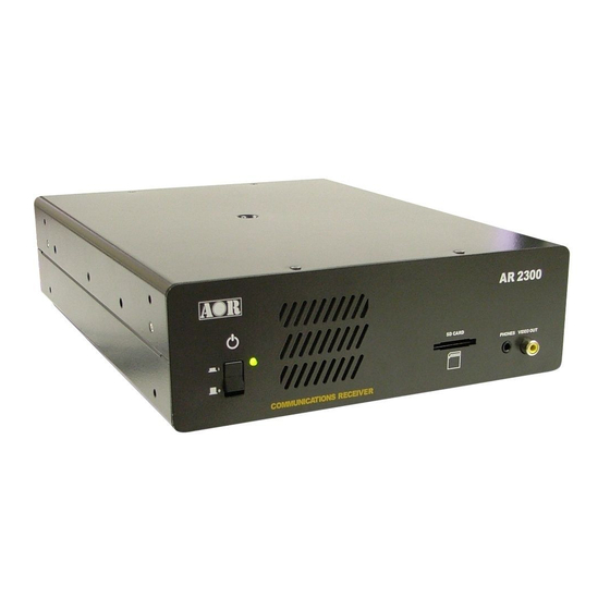
Page 7: Front/Rear Panel Description
2. FRONT/REAR PANEL DESCRIPTION 2.1. Front panel If you need to disconnect the AC power adapter, make sure that the receiver is shut ① Power switch down before. ② Status LED Green: Power on and receiving, Orange/yellow: Stand-by, Not lit: Off To mute the speaker audio while setting up the receiver and control software, simply ③... -
Page 8: Rear Panel
2.2. Rear panel ① ANT 1 Type N socket (50Ω) for frequencies over 25MHz only. ② ANT2/HF Type N socket (50Ω) for all frequencies, including HF. SMA type socket (50Ω) ③ 10MHz IN External reference clock input of 10MHz (2dBm±2dB). When a valid 10MHz is entered, it automatically switches to that external input. - Page 9 Φ3.5mm monaural jack (Up to 2W with 8Ω load) ⑧ SP OUT To connect to an external speaker. Φ3.5mm stereo jack (600Ω -10dBm) To connect to an external recording device, or an audio amplifier. Can be ⑨ LINE OUT switched to output a 12kHz wide analog I/Q signal. In dual-band reception, the main frequency is audible at the right side and the sub-frequency at the left side.
-
Page 10: Preparing For Pc Control
3. PREPARING FOR PC CONTROL The supplied AR2300 CONTROLSOFT software features complete receiver control, audio recording/playback and memory bank management for the AR2300 receiver. 3.1 PC requirements Minimum PC system: Supported OS: Windows 7/8.1/10 2GHz Dual Core CPU ... - Page 11 4. After Windows has automatically downloaded and installed the driver, Device Manager will list it as pictured: The auto-assigned COM number depends on your PC configuration.
-
Page 12: Control Software Operation
Push the power switch on the receiver’s front panel. The LED will turn orange/yellow, indicating the stand-by mode. 4.3 Starting the control software Copy the folder “AR2300 CONTROL SOFT” from inside the CD to any folder on your PC. The software does not need to be installed; it can be run as is. -
Page 13: Software Windows Description
4.4 Software windows description Any or all of the following windows can be displayed. Main Control Spectrum display / Menu bar / database Ctrl1 S-Meter Ctrl2 Mode etc. Ctrl3 AF, RF, SQL control Ctrl4 FFT control Ctrl5 Option settings Ctrl6 Frequency panel In the menu bar, go to WINDOW to select your choice of windows to display. -
Page 14: Main Control Window Description
4.4.1 MAIN CONTROL WINDOW DESCRIPTION FREQUENCY (Min.: 0000.040000 MHz, max.: 3150.000000 MHz) Change the receive frequency by either: -Hovering with the mouse over each digit and scrolling the mouse wheel up or down. -Entering the frequency via the PC keyboard + ENTER key for MHz. -
Page 15: Spectrum Display Description
4.4.2 SPECTRUM DISPLAY DESCRIPTION Click the icon to switch to waterfall display. SPECTRUM DISPLAY Spectrum displayed in real time. Receive frequency is A waterfall display is the variation of signal strength in the center frequency. conjunction with the time elapsed. The color will vary Left (single) click on spectrum: Receiver is tuned to the depending on the signal amplitude. - Page 16 4.4.3 MENU BAR DESCRIPTION (continued) Here you can select whether or not to display the toolbar and status bar, depending on the available desktop space. Power the receiver ON or OFF. Power off does actually put the receiver in standby mode, as to be completely off, the receiver’s front panel switch has to be used.
- Page 17 Priority Operation: The priority feature permits checking for activity on one of the 2000 memory channels, while the AR2300 continues scanning, searching or monitoring. The receiver is momentarily tuned to the priority channel frequency to listen for any signal. If activity is found, the receiver will remain on the active frequency until the signal disappears.
-
Page 18: Database Window Description
List-up of all audio recordings in "wav" format. Lists all pass frequencies created during a bank search. Each (AR2300 line-out needs to be connected to line-in entry can be enabled, disabled or erased. Max. 30 pass of PC audio card) frequencies per bank. -
Page 19: Description Of Control Windows 1 And 2
4.4.5 DESCRIPTION OF CONTROL WINDOWS 1 AND 2 The S-meter indicator shows the relative strength for the received signal in dB. Stored tunable data that contains frequency, step, attenuator, etc. Each click on this icon toggles between the 4 available VFOs (A~D). SEARCH The receiver sweeps between previously set start and end frequencies, in search of active frequencies. -
Page 20: Description Of Control Windows 3 And 4
4.4.6 DESCRIPTION OF CONTROL WINDOWS 3 AND 4 STEP This is the frequency increment used when selecting a frequency using the blue tuning dial, or the PC keyboard's left and right arrows. 0.001kHz to 999.999kHz in 0.001kHz increments. AF GAIN Speaker and headphone volume slider. -
Page 21: Description Of Control Window 5
RF preselection filters help to prevent overloading caused by strong out of band interfering signals. Only for frequencies below 25MHz. VIDEO Enables the video-out on the AR2300 front panel. Decodes and displays only analog video signals. Standard of the video display connected must match the video standard of the transmission. -
Page 22: Description Of Control Window 6
4.4.8 DESCRIPTION OF CONTROL WINDOW 6 To input a frequency, click on the ten-key digits and validate with kHz or MHz. To cancel the last entered digit, click the CLR key. -
Page 23: Ar2300 Specifications
5. AR2300 SPECIFICATIONS... - Page 24 AOR, LTD. 2-6-4 Misuji, Taito-ku, Tokyo 111-0055, Japan www.aorja.com Authority on Radio Communications No portion of this manual may be reproduced in English or any other language without the permission of AOR, LTD. ©2020 AOR, LTD. All rights reserved.
Need help?
Do you have a question about the AR2300 and is the answer not in the manual?
Questions and answers