Table of Contents
Advertisement
Quick Links
Download this manual
See also:
Operating Manual
Advertisement
Table of Contents

Related Manuals for AOR AR-DV10


Summary of Contents for AOR AR-DV10
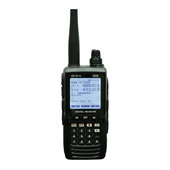
- Page 1 ® DIGITAL RECEIVER AR-DV10 Operating manual AOR, Ltd. Authority On Radio Communications Stay up to date! Operating manual addendum and firmware updates available at http://www.aorja.com/receivers/ar-dv10.html...
- Page 3 Please read this operating manual carefully. This information will allow you to enjoy maximum performance from your receiver. We sincerely hope that the AR-DV10 will be your monitoring companion for many years to come. All product names referenced herein are trademarks of their respective manufacturers.
-
Page 4: Table Of Contents
TABLE OF CONTENTS SAFETY PRECAUTIONS ....................4 1. SUPPLIED ITEMS...................... 5 2. CONTROLS & CONNECTORS ................. 6 2.1. TOP PANEL ......................6 2.2. FRONT PANEL ......................6 2.3. LEFT SIDE ......................7 2.4. RIGHT SIDE ......................7 2.5. REAR PANEL ......................8 2.6. - Page 5 7.3. SCAN PASS ......................30 7.4. BROWSE MEMORY BANKS/CHANNELS ............30 7.5. EDIT A MEMORY CHANNEL ................31 7.6. ASSIGN TITLES TO MEMORY BANKS ..............32 7.7. CREATE A GROUP OF LINKED MEMORY BANKS ..........32 7.8. SCAN A GROUP OF LINKED MEMORY BANKS..........34 7.9.
-
Page 6: Safety Precautions
• during hot seasons, as it could initiate a fire, or degrade the battery performance. Use only the supplied AOR battery pack with the supplied AOR power adapter. The • supplied power adapter is tested and approved for use with the supplied AOR battery pack. -
Page 7: Supplied Items
SUPPLIED ITEMS ・ AR-DV10 Digital Receiver (including antenna ring) ..........1 ・ AA-10* AC power adapter ................... 1 ・ BP-10 Lithium-ion battery pack ................1 ・ CC-10 Fast charger cradle ................. 1 ・ BC-10 Belt clip ....................1 ・ RA-10 Antenna .................... -
Page 8: Controls & Connectors
CONTROLS & CONNECTORS 2.1. TOP PANEL (1) Antenna jack (BNC 50 ) Attach the supplied flexible antenna or connect an external antenna. (2) Antenna ring Covers the gap between the antenna and the jack. Remains on the jack when the antenna is removed. -
Page 9: Left Side
(18) DATA jack (USB mini-B socket) Lift the rubber cover to connect a USB cable for command control. (No AOR software supplied.) (19) EXT DC jack To power the receiver from an external source, connect either the supplied AC power adapter or the cigarette lighter DC/DC converter. -
Page 10: Rear Panel
2.5. REAR PANEL (20) Belt clip screw holes Mount the belt clip here using the 2 supplied screws. When the belt clip is not used, it is important to affix the screws to the body to prevent water entering these holes. (21) Belt clip (22) Battery pack Only use the supplied lithium-ion battery... -
Page 11: Lcd Display
2.7. LCD DISPLAY 1 → 2 → 3 → 4 → 5 → 6 → 7 → Section Icons Key lock status All controls except VOL and PWR are disabled. Press and hold to enable/disable the lock feature. Remote control status ◉... - Page 12 Operation mode [VFO] [VFO]: VFO [MEM]: Memory channel readout [SCN]: Scan [SER]: Search FM15 Demodulation modes (IF bandwidth in kHz or Hz): FM100, FM30, FM15, FM6 (kHz) AM15, AM8, AM5.5, AM3.8 (kHz) USB2.6, USB1.8, LSB2.6, LSB1.8 (kHz) CW500, CW200 (Hz) IF bandwidths for digital modes: FM30, FM15, FM6 (kHz) Digital demodulation is activated.
- Page 13 BUSY (The squelch is open) S-Meter signal strength meter (relative signal strength). Relative signal strength of incoming signal is indicated in standard S units, from S1 to S9. Calibration above S9 is in dB up to +60dB. microSD card Solid: Card ready Blinking: Checking, please wait.
- Page 14 Go to next NEXT Toggle between search, scan and VFO. S<->Z Copy date and time information COPY...
-
Page 15: Power Supply
POWER SUPPLY CAUTION REGARDING THE LITHIUM-ION BATTERY PACK. ・ Do not leave the charger connected to the receiver for continuous periods in excess of 24 hours. Long term overcharging can degrade the lithium-ion battery pack and significantly shorten its useful life. ・... -
Page 16: Battery Pack Charging
3.2. BATTERY PACK CHARGING It is necessary to charge the lithium-ion battery fully before its first use. 1. Install the battery pack onto the receiver. Ensure that the receiver is switched OFF. 2. Insert the AC power adapter DC plug into the jack located on the back of the fast-charger cradle, then plug the AC power adapter into an AC line outlet. -
Page 17: Powering With Alcaline Batteries
If the AC power adapter is connected to the fast charger cradle, when the receiver is inserted into the cradle, the cradle’s LED will first turn red, indicating a charging status. When the battery pack is fully charged, the LED will turn green. A flashing red LED indicates a charging error. -
Page 18: Powering With Cigarette Lighter Dc/Dc Converter
EXT-DC socket Important: : : : ・ Do not connect any accessory not approved by AOR to supply DC power; otherwise the receiver may be damaged. ・ The AOR cigarette lighter DC/DC converters supplied for other AOR receivers are not... -
Page 19: Antenna
ANTENNA The AR-DV10 is supplied with a flexible rubber antenna to be attached to the 50 Ohm BNC jack located on the top of the receiver. Note: ・ AR-DV10 does not feature any internal AM ferrite antenna. ・ Due to physical limitations, the supplied flexible rubber antenna is not ideal for reception of LW, MW or SW. -
Page 20: Basic Operation
BASIC OPERATION 5.1. POWER ON/OFF To power the receiver ON, briefly press the red power button. The boot sequence will start when the button is released, it takes about 3 seconds for the receiver to be ready for operation. To power the receiver OFF, press and hold the red power switch for 3 seconds. Release the button after 3 seconds, and the shutdown sequence will complete. -
Page 21: Vfo Mode Reception
5.3. VFO MODE RECEPTION The AR-DV10 has three VFOs, VFO-A, VFO-B and VFO-Z, each VFO has independent receive frequency, demodulation mode, frequency step, etc..settings. However only one VFO can be selected and received at a time. VFO currently being received To select VFO-A: Press [MENU] and [ENT] twice. -
Page 22: Receive Mode Selection
B) TURNING THE DIAL SELECTOR KNOB Turn the dial selector knob on the top panel to select the desired operating frequency. The step increment per knob click is according to the frequency step displayed at the top right corner of the screen. (See chapter 5.8 “TUNING STEP” to change this step value.) C) USING THE [◀] and [▶] KEYS (fast tuning method) Press [▶] to increase or [◀] to decrease the frequency. -
Page 23: If Bandwidth Selection
5.6. IF BANDWIDTH SELECTION The appropriate IF bandwidth may to be set manually for each analog demodulation mode. However for digital modes, the IF bandwidth is automatically selected and cannot be changed. After the desired analog mode has been set, access the IF bandwidth menu as follows: Long press [MODE] and use [ ▶... -
Page 24: Tuning Step
Squelch is adjusted as follows: Press the [SQL/MONI] switch on the left side of the receiver, that will select [NSQ:010] as shown in the illustration on page 21. Rotate the DIAL knob selector to set the squelch threshold so that the receiver is just silenced. -
Page 25: Step-Adjust
The tuning step value can be changed as follows: Press [MENU], then press [ENT]. Use [▶] to select [STEP], then press [ENT]. Note that there are 3 pages of values from 10Hz ← up to 500kHz. Use the arrow keys [◀] or [▶] to select the desired step and press [ENT] to validate the setting. - Page 26 Use the arrow keys [◀] or [▶] to select the desired value, then press [ENT] to validate the setting. Note: The maximum value which can be set, corresponds to half the frequency step set in section 5.8 “TUNING STEP”.
-
Page 27: Audio Recording
AUDIO RECORDING The received audio can be recorded in MONO on a microSD card and played back. Note: ・ When a microSD card is inserted, the receiver might take more or less time to read the card’s content, depending on the size of the card. When the icon is still blinking, it means that the receiver is currently reading the card. -
Page 28: Playback
Select ON or OFF by rotating the DIAL selector knob. Press [ENT]. 6.4. PLAYBACK Audio which has been recorded using the AR-DV10 can be played back directly on the AR-DV10. Long press on [ ● ], then press [ENT]. ◯ The recording files list is displayed. -
Page 29: Memory Channel & Scan Operations
MEMORY CHANNEL & SCAN OPERATIONS AR-DV10 can store 2000 memory channels, divided into 40 banks of 50 memory chan- • nels each. Frequencies can be conveniently stored into “memory channels”, along with the • Modulation Type, IF bandwidth, etc... Frequently used groups of frequencies can be stored into “memory banks”, which can be •... -
Page 30: Scan A Memory Bank
Use the keypad to enter the frequency in MHz, followed by [ENT]. FREQ: Rotate the dial selector knob to select the desired modulation type, and press MODE: [ENT]. Rotate the dial selector knob to select the desired IF bandwidth, and press IFBW: [ENT]. - Page 31 To scan a memory bank: Go to [MENU], use the [▶] button to select [SCAN] and press [ENT]. Use the [▶] button to select [BANK] and press [ENT]. Enter the number of the bank to be scanned using the keypad. Scan will start immediately.
-
Page 32: Scan Pass
7.3. SCAN PASS The scan pass function may be marked as a memory channel to be ignored during scan. This is useful to temporarily disable memory channels, without having to erase them. For example, while scanning a memory bank, if scan has stopped on an active signal, but you want to bypass this frequency for future scans. -
Page 33: Edit A Memory Channel
7.5. EDIT A MEMORY CHANNEL A memory channel which already contains a saved frequency, can be edited as follows: Press [MENU] and use the [▶] button to move to [MEM] and press [ENT] Use the [▶] button to move to [CH EDIT] and press [ENT] twice. Use the keypad to enter the bank number and channel number, followed by [ENT]. -
Page 34: Assign Titles To Memory Banks
Set the voice descrambler function as described in chapter 10.6 “ANALOG V.SCR: VOICE DESCRAMBLER”. Finally save all the settings: Use the [▶] button to go to the line 9, [MEM CH PARAM SET] and press [ENT]. 7.6. ASSIGN TITLES TO MEMORY BANKS A title may be assigned to each memory bank, and PROTECTON set, so the bank is not accidentally erased. - Page 35 Create a scan group: Press [MENU], use the [▶] button to select [SCAN], then press [ENT]. Use the [▶] button to select [GRP EDIT], then press [ENT] twice. Enter the scan group number to be created, with the keypad. This illustration shows an example of scan group 0 and all bank numbers from 00 to 39 which can be linked, providing they already have frequencies registered.
-
Page 36: Scan A Group Of Linked Memory Banks
7.8. SCAN A GROUP OF LINKED MEMORY BANKS Select the scan group of linked memory banks to be scanned: Press [MENU], use the [▶] button to select [SCAN], then press [ENT]. Use the [▶] button to select [GRP], then press [ENT]. Input the scan group number with the keypad, then press [ENT]. -
Page 37: Priority Reception
If activity is found, the AR-DV10 will remain on the active frequency until the signal disappears. If no activity is detected, the receiver returns to the original VFO frequency, scan channel or search bank. -
Page 38: Program Search
PROGRAM SEARCH This function tunes the receiver through all frequencies between two specified frequency • limits in the predetermined step size, looking for active frequencies. The search instructions may be programmed into “search banks”. • There are 40 search banks, numbered from 00 to 39. •... -
Page 39: Run A Search
PROTECT: Rotate the dial knob to toggle protect ON or OFF, and press [ENT]. When set to ON, this search bank cannot be erased. (refer to page 2/2) Rotate the dial knob to choose between LEVEL, NOISE or AUTO squelch. SQL N/L: SQL TYPE: Rotate the dial knob to choose between CTCSS, DCS, reverse tone and OFF. -
Page 40: Search Pass
To copy a search channel to VFO: When search has stopped on an active frequency of interest, this frequency channel, • along with all its VFO settings, can be copied to receiver VFO-Z. Press [ENT] to copy to VFO-Z Press [ENT] to return to search 9.3. -
Page 41: Create A Group Of Linked Search Banks
9.4. CREATE A GROUP OF LINKED SEARCH BANKS There are 10 search groups (numbered 0 to 9) that may be set up individually to search a group of linked search banks. Each search group can be setup with its own squelch parameters as follows: Delay time: Time between the signal dropout and squelch closing, for search to resume. -
Page 42: Search A Group Of Linked Search Banks
Free time: This is the time after which scanning will resume, whether or not the signal drops out. Free time can be set between 1 and 60 seconds. [OFF] means search will only resume after the signal drops, as set in “Delay time”. Default is [OFF]. - Page 43 Use [▶] to select any of the following categories in order to perform data COPY, MOVE or ERASE data: SEARCH BANK: For an entire search bank. SEARCH GRP: For a search group. Press [ENT] and rotate the dial knob to choose: COPY: To copy data MOVE: To move data (the original entry will be deleted)
-
Page 44: Advanced Operation
10. ADVANCED OPERATION 10.1. SIGNAL ATTENUATOR This function is used to lower the receiver sensitivity in case the signal is too strong (audio is distorted), thus overloading the receiver RF stage. The attenuation is approx. 10dB. However the S-meter value remains unchanged. Press [MENU] then use [▶] to select [OPT] and press [ENT]. -
Page 45: Input Characters & Symbols
When manual gain RF-G is selected, then set the gain level as follows: Press [MENU], then press [ENT]. Use [▶] to select [CONF], then press [ENT] Use [▶] to select [RF-GAIN], then press [ENT] Select the desired gain level (between 000 and 255) with the dial knob. -
Page 46: Data Editor (Copy, Move, Delete)
An alternative method to select characters and symbols is by rotating the dial knob. This method gives a wider choice of symbols than the key entry. ABCDEFGHIJKLMNOPQRSTUVWXYZ[\]^_` abcdefghijklmnopqrstuvwxyz{|}~ (blank space) !”#$%&’()*+,-./0123456789:;<=>?@ 10.4. DATA EDITOR (COPY, MOVE, DELETE) The contents of memory channels, memory banks, scan groups, search banks, and search groups may be copied, moved, and erased. -
Page 47: Advanced Squelch Types
10.5. ADVANCED SQUELCH TYPES 10.5.1. CTCSS & REVERSE TONE Continuous tone-coded squelch system (CTCSS) is a function which opens squelch only when a preset tone frequency is detected in the signal. Otherwise the audio will be muted. The tone code squelch only functions in FM mode, with IF bandwidth set to 6kHz or 15kHz. -
Page 48: Dcs
10.5.2. Digital-code squelch (DCS) function opens squelch only if a preset DCS code is detected in the signal. At other times, audio will be muted. DCS functions only in FM mode with IF bandwidth set to 6kHz or 15kHz. Basically, DCS functions the same as CTCSS; however, there are more DCS codes available. -
Page 49: Analog Voice Descrambler
There are only 32767 possible combinations, between 00001 and 32767. 00000 no scramble code used. Note: AR-DV10 also has an exclusive scramble code auto detect feature. While receiving a scrambled signal, press the key-lock key and “D-CR ENC.CODE” with a blinking “?”... - Page 50 ・(line 2) DMR slot selection Only the selected slots will be decoded. Both slots but priority on SLOT1 Both slots but priority on SLOT2 SLOT1 only SLOT2 only ・(line 3) DMR COLOR When set to ON, the receiver will only decode signals corresponding to the color code number set in the (line 4) DMR COL C column.
-
Page 51: Offset Reception
10.8. OFFSET RECEPTION AR-DV10 can be easily programmed to shift the receive frequency by a preprogrammed value. This is useful when receiving two-frequency radio communications, such as a base station and a mobile station or a relay station, that transmit to each other on two frequencies. -
Page 52: Receiver Settings
11. RECEIVER SETTINGS 11.1. CALENDAR & CLOCK Press [MENU], then use [▶] to select [CLK] and then press [ENT] Using the number keys, input the date and time in the following format: YY-MM-DD HH:MM For example: for 18-01-30 15:00 (Jan.30, 2018 at 15:00) just enter 1801301500, then press [ENT] to save the setting. - Page 53 All MENU settings are returned to factory default. Memory data is retained. 5 FULL RESET All settings are returned to factory default and all memory data is deleted. 6 FACTORY MENU Access is restricted to AOR Service Department. 7 FIRM Displays the firmware version.
- Page 54 8 SER. Displays the serial number of the receiver. 9 SYS.UPDATE To apply a firmware update using the SD card. Download the latest firmware version at http://www.aorja.com/receivers/ar-dv10.html...
-
Page 55: Receiver Data Backup & Restore
12. RECEIVER DATA BACKUP & RESTORE MAKE A BACKUP Receiver system settings and memory data may be saved to the microSD card. The recorded .CSV files may also be edited on a PC and then uploaded to the receiver. Long press on [ ● ] Select [BACKUP] using the [▶] button and then press [ENT]. - Page 56 RESTORE A BACKUP Backups saved on the SD card can be restored to the receiver. To facilitate the handling of multiple backups, file names may be changed if desired, as long as they are up to 8 ASCII characters. The receiver will recognize the kind of backup, no matter what file name is assigned.
-
Page 57: Firmware Update
This could potentially corrupt system data and make the receiver unusable. Such a happening would not be covered by the manufacturer warranty. ・ The firmware is the property of AOR Ltd. and should not be re-distributed, either in its original form or in any modified form. - Page 58 Press [MENU], then use [▶] to select [CONF], followed by [ENT]. Press [▶]until [SYS UPDATE] is displayed, then press [ENT]. The firmware file will be automatically displayed. If more than one firmware file is stored to the card, select the desired file. Press [ENT] to start the update.
-
Page 59: Troubleshooting
14. TROUBLESHOOTING If the receiver appears to be defective, please check the following Q&A troubleshooting assistance chart before contacting AOR. If the device cannot be operated properly after reviewing the assistance information, kindly contact an AOR dealer for instructions. Symptoms... - Page 60 ・ Wait for the next transmission D-STAR call sign is not Header of the transmis- displayed. sion has not been re- (header) to be received and de- ceived. Especially dur- coded. ・If cause is unstable signal, try a ing SCAN and SEARCH, hitting a signal in the better location or larger antenna.
-
Page 61: Specifications
15. SPECIFICATIONS Frequency range 100kHz~1300MHz (Cellular frequencies blocked for US consumer version) Operation modes VFO, memory channel, program search, scan Analog receive modes WFM, NFM, AM, USB, LSB, CW Digital receive modes TETRA(Direct mode, mobile to mobile),DMR(Tier1/2/Mototrbo), NXDN(6.25k), dPMR(446 Tier1), APCO25(Phase1), D-STAR, Yaesu(C4FM), Alinco(EJ47U), Japanese D-CR. - Page 62 Digital voice mode compatibility chart: AR-DV10 DIGITAL COMPATIBLE MODE ENCRYPTED / TRUNKED MODULATION VOICE MODE BANDWIDTH VOCODER DECODING GMSK 12.5kHz AMBE D-STAR GMSK 12.5kHz EJ-47 (VOICE F1E) AMBE ALINCO C4FM 12.5kHz AMBE+2 YAESU VOICE FR NON-ENCRYPTED C4FM 6.25kHz AMBE+2 D-CR...
-
Page 63: Declaration Of Conformity
® Declaration of Conformity We, AOR Ltd. certify and declare under our sole responsibility that the following equipment complies with the essential requirements of the Directive 89/336/EWG changed by 2004/108/EWG v.19.04.2016; 19.04.2016; 2014/30/EU and low voltage Directive 2006/95/EG. Type of Equipment:... - Page 64 2-6-4, Misuji, Taito-Ku, Tokyo, 111-0055, Japan URL: www.aorja.com Authority On Radio Communications No portion of this manual may be reproduced in English or any other language without the permission of AOR, LTD. ©2018 AOR, LTD. All rights reserved. E.U/US(U) v.2018-04-18...
Need help?
Do you have a question about the AR-DV10 and is the answer not in the manual?
Questions and answers