Table of Contents
Advertisement
Quick Links
Download this manual
See also:
Operating Manual
Advertisement
Table of Contents

Subscribe to Our Youtube Channel
Related Manuals for AOR AR-ONE


Summary of Contents for AOR AR-ONE
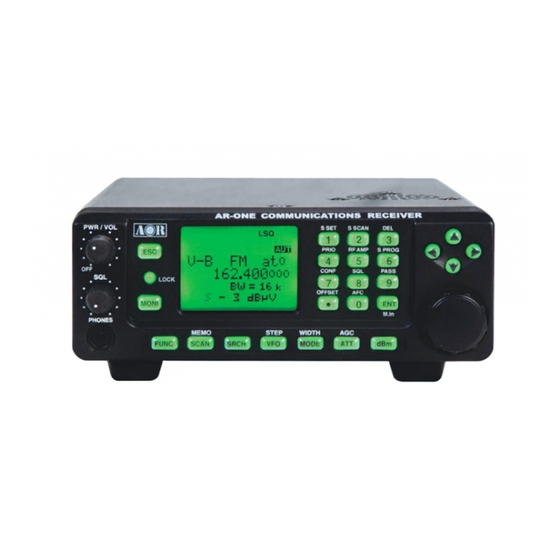
- Page 1 ® AR-ONE Ultra Wide Band Communications Receiver Operating manual AOR, LTD.
-
Page 2: Table Of Contents
1-6 Computer control ---------------------------------------------------------------------------- 12 1-7 IF output and Spectrum Display Unit (SDU5600) ----------------------------------- 12 2 Getting Started -------------------------------------------------------------------------------------------- 13 2-1 Making the AR-ONE ready for operation ---------------------------------------------- 13 2-1-1 LCD ------------------------------------------------------------------------------ 13 2-1-2 Connect the antenna -------------------------------------------------------- 13 2-1-3 Connect power ---------------------------------------------------------------- 13... - Page 3 3 Memory channels and banks ----------------------------------------------------------------------- 24 3-1 Memory channel overview -------------------------------------------------------------- 24 3-2 Storing VFO frequency and data into memory ------------------------------------- 25 3-3 Memory read “M.RD” --------------------------------------------------------------------- 26 3-4 Deleting memory channels -------------------------------------------------------------- 27 4 SCAN – scanning memory channels -------------------------------------------------------------28 4-1 SCAN –...
- Page 4 7 Computer control --------------------------------------------------------------------------------------- 52 7-1 How to send an RS-232C command ------------------------------------------------- 52 7-2 Power on the AR-ONE ------------------------------------------------------------------- 52 7-3 Detailed RS-232C Command Listing of the AR-ONE ---------------------------- 53 8 Reset -------------------------------------------------------------------------------------------------------- 66 9 Specifications -------------------------------------------------------------------------------------------- 67 10 Optional Accessories -------------------------------------------------------------------------------- 70...
-
Page 5: Introduction
1-1 Introduction Thank you for purchasing the AR-ONE Ultra Wide Band Communications receiver. The AR-ONE is designed using the very latest technology to ensure the highest levels of performance and reliability. To get the best possible results from your AR-ONE, we strongly recommend you to read this manual and familiarize yourself with the receiver. -
Page 6: Taking Care Of Your Radio
Always keep the AR-ONE free from dust and moisture. Use a soft, dry cloth to gently wipe the set clean, never use abrasive cleaners or organic solvents which may damage certain parts. -
Page 7: Attention While Operating
SAFETY NOTICE – Always disconnect the power supply from the AC outlet when not in use. If used mobile, it should be noted that the AR-ONE has NOT been manufactured or tested to meet any specific mobile safety requirements. The AR-ONE has no internally user adjustable parts. - Page 8 & scan functions to operate. This is because the AR-ONE believes that it has found an active frequency when the squelch opens and “S” ‘squelch open’ icon is displayed to the left of the signal meter.
-
Page 9: Accessories Supplied
AR-ONE receiver DC power cable Operating manual 1-5 Controls & functions Controls are located on the front with most connectors on the rear of the AR-ONE, a brief identification is given here: Front Panel 1. Volume control plus isolate power On/Off 2. - Page 10 The REMOTE RS-232C connectors (17 & 18 above) are designed for connection directly to a RS-232C serial port of a PC. By daisy chaining the units, control of up to 99 AR-ONE receivers is possible from one PC. No interface is required, just a standard RS-232C straight cable.
-
Page 11: 1-5-1Keypad
LOCK This key is intentionally small to reduce the chances of accidental operation. Key lock is useful when you do not wish an important frequency to be lost or the AR-ONE to be incorrectly set to a different frequency. To force the squelch open so that you may manually intervene to ensure that no weak signals are missed. - Page 12 RF Attenuator. Move the cursor to select the desired parameter. The AUTO selection will work best for most of cases. Automatic Gain Control. Move the cursor to select the desired AGC time constant. Usually, FAST is used to receive CW, MEDIUM for AM and FM, and SLOW for SSB. When MANU is selected, any desired parameter (between 0 –...
-
Page 13: Computer Control
CONFIG menu. Baud rates (transfer speed) can be set to 9600, 19200 (default) or 38400 bps. Since there are two independent RS-232C ports with the AR-ONE, it is possible to set an ‘address’ to facilitate connection of up to 99 AR-ONE receivers to a single PC. -
Page 14: Getting Started
2-1-3 Connect power Connect power to the DC power jack on the rear panel of the AR-ONE. For optimal performance use a regulated DC power supply (12 ~ 14 V with capacity 2A). Do not connect to a 24 V system. -
Page 15: Squelch Circuit
The AR-ONE will take approximately 4 - 5 seconds before information appears on the LCD. This is normal, while the AR-ONE microprocessor generates the ‘boot up data’ required to control the receiver. 2-3 Squelch Circuit In normal use, NOISE SQUELCH is used. However, LEVEL SQUELCH can be selected for search and scan operations. -
Page 16: Vfo Selection
6. To select NOISE SQUELCH, repeat above steps. 2-4 VFO selection The AR-ONE has ten (10) VFOs being identified as “V-A” through “V-J” on the top left of the LCD. The term VFO historically means ‘Variable Frequency Oscillator’ and today refers to a tunable data store which contains frequency, step, step-adjust, attenuator etc. -
Page 17: Changing Frequency Using The Main Tuning Dial
For your convenience, receive mode and tuning step size have been pre-programmed into the AR-ONE auto-mode band plan data at the factory to simplify operation of the receiver, especially while you familiarize yourself with all functions. Should you wish, the defaults may be manually overridden at anytime so that you may select an alternative receive mode and tuning step on any frequency. -
Page 18: Auto Mode Selection
WFM – Wide Band Frequency Modulation – used by VHF and UHF broadcast stations as excellent audio quality is available due to the relatively wide frequency bandwidth employed. Used only for local services such as VHF band stereo (received as mono on the AR-ONE) and UHF TV sound channels. -
Page 19: Receive Mode Selection
Note: Auto-mode is cancelled as soon as the receive mode, tuning step or other related data is changed. Remember that auto-STEP and auto-MODE are linked, reselect AUTO-MODE if either have been adjusted and you require the auto band plan selection. 2-5-2 Receive mode selection Any receive mode may be selected at any frequency within the receiver’s frequency coverage. -
Page 20: If Bandwidth
The bottom line of the LCD displays the icon “STEP SET” to indicate that the AR-ONE is Waiting for you to change the step size. Use the main tuning dial or arrow key to select the desired step size. To accept the displayed tuning step size, push the ENT key. -
Page 21: Manually Selecting If Bandwidth
An appropriate IF filter is automatically selected when auto mode is engaged. However any combination of IF filter and receive mode is possible in manual mode. When you have manually selected an IF filter bandwidth, auto mode will be disengaged, but the receive mode, step size, etc will be retained until they are changed manually. -
Page 22: Att (Attenuator)
When MANU is selected, a desired parameter can be entered between 0 ~ 255 in the Configuration Menu. 2-9 ATTENUATOR Activating the attenuator reduces signals to the RF input stages of the AR-ONE to prevent overloading, for example when the receiver is used in close proximity to strong transmissions. -
Page 23: Rf Amplifier
2-10 RF AMPLIFIER The AR-ONE features a preamplifier. The LCD icon “a” is used to display the setting in use. To change the RF Amplifier setting, push the FUNC key and then push the 5 key. Select a new AMP parameter from the list of ON, OFF, AUTO by rotating the main tuning... -
Page 24: Offset
2-11 OFFSET This function enables the receive frequency to be quickly SHIFTED by a predetermined value, this makes it easy to track duplex-transmissions or check repeater inputs/outputs. The locations for frequency offset storage are numbered 00 to 47 with 00 acting as OFF, this makes 47 locations available. -
Page 25: Memory Channels And Banks
Think of memory channels as pages in a notebook, each of which is numbered to identify it. Data may be written to each new page (memory channel) and each page may be overwritten with new data, they can be used over and over again. The AR-ONE has 1,000 memory channels and one priority channel. -
Page 26: Storing Vfo Frequency And Data Into Memory
100 channels. The memory banks are identified by the first BANK number 0, 1, 2, 3, 4, 5, 6. 7, 8 and 9 and the individual channels are numbered from 00 to 99. Examples are “000” for the first channel location in memory bank “0” and “099” for the last memory channel in memory bank “0”. -
Page 27: Memory Read "M.rd
“325” during an earlier example in the preceding section. Push the FUNC key and push the SCAN key to go into memory read mode, the “M.RD” icon appears on the top left of the LCD to confirm operation. The AR-ONE will monitor... -
Page 28: Deleting Memory Channels
The AR-ONE will display memory channel, mode, text comment (if one was used). The memory channel last used (for memory write or recall) will initially be displayed. If the desired memory channel is not immediately displayed, it may be recalled by keying in the required three digit location. -
Page 29: Scan - Scanning Memory Channels
During SCAN, the AR-ONE automatically recalls memory channels which contains data in numeric order and monitors them looking for activity. When an ‘active’ memory channel is located (when a signal is found and the squelch is open), the AR-ONE will temporarily stop scanning. -
Page 30: Selecting A Scan Bank
When SCAN has been selected, only the currently displayed memory bank WHICH CONTAINS DATA will be SCANNED, receive mode and frequency are unimportant. Any memory channels which contain no data (empty) will be ignored (skipped). 4-3 Selecting a scan bank The memory bank identifier (such as “3”) will be displayed on the middle right of the LCD. -
Page 31: Search Mode
To stop select scan, push the VFO key. 5 Search mode In search mode, the AR-ONE is programmed to automatically tune between two specified frequency limits looking for activity. Please refer to section 1-3 of this manual if you do not fully understand the function of SEARCH. -
Page 32: Starting Program Search
LO (lower) start frequency HI (upper) stop frequency Receive mode (or set to AUTO MODE) Step (if auto is not selected) Text comment The program search banks are identified by numbers (01 ~ 40). To help with identification, each bank may be labeled with an alphanumeric text comment. 5-2 Staring program search Presuming that data is already stored into a search bank …... -
Page 33: Forcing The Search To Resume
5-2-2 Forcing the search to resume If the AR-ONE stops on an unwanted busy frequency, rotate the main tuning dial knob or use the up arrow key or down arrow key to force the search process to resume from the current frequency displayed. - Page 34 Use the main tuning dial, right arrow key, left arrow key or keypad to select the bank you wish to program or overwrite (The down arrow key is used to move through the menu). Push the down arrow key.
- Page 35 LO: Input the lower start frequency in MHz format (don’t push the ENT key). Push the down arrow key. HI: Input the higher end (stop) frequency in MHz format (don’t push the ENT key). Push the down arrow key.
- Page 36 MODE SET: Use the right arrow key or left arrow key or main tuning dial to select receive mode, the FUNC key is used as a short cut to “AUTO”. Note: If the receive mode is set to “AUTO”, the receive mode, channel step will be taken from the pre-programmed auto band plan data, for this reason the detailing will not be required and skipped.
-
Page 37: Deleting Search Banks
To accept the data input, push the ENT key. 5-5 Deleting search banks A delete menu is provided so that you can delete program search data (of course you may simply overwrite the data, too) . While in search mode, the DELETE menu is accessed as follows: Push the FUNC key and then push the 3 key. -
Page 38: Locking Out Unwanted Active Frequencies (Pass)
Push the down arrow key. Using the main tuning dial, keypad, right arrow key or left arrow key, select the desired search bank. The “HI” and “LO” frequency limits will appear on the LCD along with any associated text comment to aid the identification of the required search bank. To delete the program search bank, push the ENT key. -
Page 39: Deleting Pass Channels
the PASS function before taking action or transmissions may be missed. While stopped on an unwanted frequency, push FUNC and then push the 9 key. The search process will resume. It will appear that all frequencies are still searched, however, locked out frequencies will be ‘passed over’, the search will not stop on locked out frequencies. -
Page 40: Configuration Menu
If pass channels have already been tagged for the current search bank, the icon “PAS” (PASS) will be displayed on the LCD. Push the FUNC key to delete the pass frequency. To exit from this menu, push the ENT key. 6 Configuration menu The configuration menu is used to set fundamental operating parameters and other variables which do not appear in any other menu heading. -
Page 41: Configure Beep
AUTO 6-1 Configure beep The AR-ONE emits confirmation ‘beeps’ while the keypad is used. A ‘HIGH’ pitched beep indicates correct operation while a ‘LOW’ pitched beep indicates that an error or unexpected entry has taken place. The volume of the beep is independent of the main volume control... -
Page 42: Configure Lamp
(LAMP). 6-2 Configure lamp The AR-ONE is equipped with high intensity green LEDs to illuminate the LCD and keypad when operating in areas of low level lighting. The lamp may be configured in three ways: AUTO: The lamp will automatically illuminate when the keypad or main tuning dial are used. -
Page 43: Configure Dimmer
(CONTRAST). 6-4 Configure contrast The AR-ONE is equipped with variable LCD contrast which is adjustable in 32 steps to provide best visibility under different viewing angles, extremes of ambient light & temperature (and between sets due to variation). -
Page 44: Configure If-Gain (Intermediate Frequency Gain)
is set OFF. The default setting for Manual AGC is 255, maximum gain control value. The value can be adjusted according to the receiving condition. To access the configuration menu, push the FUNC key and then push the 7 key. Push the down arrow key to move the cursor to the “MANU AGC”... -
Page 45: Configure Rf-Gain (Radio Frequency Gain)
AR-ONE (connected via a male 9-pin to male 9-pin straight cable). To access the configuration menu, push the FUNC key and then push the 7 key. -
Page 46: Configure Rmt-Id (Remote Id)
To access the configuration menu, push the FUNC key and then push the 7 key. Push the down arrow key to move the cursor to the “RMT-ID” selection point. Use the main tuning dial, the right arrow key or the left arrow key to change the AR-ONE’s RS-232C identification address. -
Page 47: Configure Free (Scan Free And Search Free)
This is useful if you wish to gain a snap shot of activity without the AR-ONE being tied to a busy frequency for long periods of time (such as when monitoring active commercial repeaters etc). -
Page 48: Configure Rear Speaker
6-12-1 Configure rear speaker To access the configuration menu, push the FUNC key and then push the 7 key. Push the down arrow key to move the cursor to the “REAR SP” selection point. This menu is to configure the rear speaker. Use the main tuning dial, the right arrow key or the left arrow key to select the desired rear speaker setting (ON or OFF). -
Page 49: Configure Audio Filters (Hpf/Lpf)
6-13 Configure audio filters (HPF / LPF) An audio HPF (High Pass Filter) and a LPF (Low Pass Filter) are available. 6-13-1 Configure audio HPF (high pass filter) The audio high pass filter is useful for limiting the audio bass response (allowing higher tones to pass) improving intelligibility in certain circumstances (such as low frequency whistles on AM, SSB &... -
Page 50: Configure Audio Lpf (Low Pass Filter)
6-13-2 Configure audio LPF (low pass filter) The audio low pass filter is useful to cut off high tones (allowing low tones to pass) to improve intelligibility of weak signals in close proximity to adjacent interference and to remove hiss making listening for extended periods easier on the ears. There are four available pass frequencies: 3KHz, 4KHz, 6KHz and 12KHz. -
Page 51: Engaging Prio Channel
The priority checking is accomplished by momentarily tuning the receive circuit to the priority frequency to see if it is active. If activity is found, the AR-ONE will remain on the active frequency until the signal disappears. If no activity is detected, the receiver returns to the VFO frequency, scan channel or search bank from where it originated. -
Page 52: Configure If Output Frequency
(Reference Signal). 6-17 Configure reference signal source The function enables you to select the reference signal of the receiver. The AR-ONE has a built-in stable reference oscillator, however, an external high stability 10 MHz reference (such as off-air atomic coupled) can be accepted from the SMA connector (marked as 10 MHz IN) on the rear panel of the AR-ONE. -
Page 53: Computer Control
(data transfer speed) may be set to 9600, 19200 or 38400 bps. 19200 bps is the factory default. It is also possible to set an ‘address’ to facilitate connection of up to 99 AR-ONE receivers to a single port for custom operation, the addresses may be set between the limits of 01 to 99 with 00 representing single radio operation. -
Page 54: Detailed Rs-232C Command Listing Of The Ar-One
Send a [CR] then re-send the command. Should problem persist, check your connections and try reducing the RS-232C baud rate. 7-3 Detailed RS-232C command listing of the AR-ONE Power on x: any key to power on the AR-ONE (it takes 4 sec.) Power off Power off ^Ann... - Page 55 FREQUENCY RFnnnnnnnnnn (entry in Hz format) (VFO mode only) RFnn.nn (entry in MHz format) (VFO mode only) Vx nnnnnnnnnn (entry in Hz format) x: A – J (VFO) To read: RF <CR> Response: RFnnnnnnnnnn (Hz) STEP FREQUENCY STnnnnnn (entry in Hz format) (not available in search mode) STnn.nn (entry in kHz format) (not available in search mode)
- Page 56 BANDWIDTH BWn (n: 0 – 8) Auto mode will be disabled by this command n=0 0.5kHz n=1 3.0kHz n=2 6.0kHz n=3 8.5kHz n=4 16kHz n=5 30kHz n=6 100kHz n=7 200kHz n=8 300kHz To read: BW <CR> Response: BWn HPF (High Pass Filter) HPn (n: 0 –...
- Page 57 AGC (Automatic Gain Control) Acn (n: 0 – 2) n=0 AGC - OFF n=1 AGC - FAST n=2 AGC - SLOW n=3 AGC - MIDDLE To read: AC <CR> Response: ACn DE-EMPHASIS ENn (n: 0 – 5) Auto mode will be disabled by this command 25μS 50μS 75μS...
- Page 58 RF AMP (Amplifier) AMn (n: 0 – 2) n=0 RF AMP OFF n=1 RF AMP ON n=2 RF AMP AUTO To read: AM <CR> Response: AMn BFO FREQ (Beat Frequency Oscillator Frequency) BF +/-nnnn (nnnn: 0000 - +/- 3000Hz) Available in CW, LSB, USB mode only Default: CW +800Hz, USB +1500Hz, LSB -1500Hz To read: BF <CR>...
- Page 59 MANUAL GAIN (10.7 MHz AGC) MGnnn (nnn: 000 – 255) Default: 255 Note: Available only when the AGC is set to OFF To read: MG <CR> Response: MG nnn RF GAIN RGnnn (nnn: 000 – 255) Default: 255 Note: volume control knob must...
- Page 60 AUTO SIGNAL LEVEL n:0 Auto Signal Level off n:1 Auto Signal Level on While n is set to 1, and the squelch opens, the signal level and frequency information is sent to the PC To read: LC <CR> Response: SQm LMnnn RFnnnnnnnnnn m: 0 Noise squelch mode m: 1 Level squelch mode nnn: signal level from 000 to 999...
- Page 61 BACKLIT DIMMER LDn (n: 0 or 1) n: 0 NORMAL (Default) n: 1 DIMM To read: LD<CR> Response: LDn LCD CONTRAST LVnn (nn: 00 – 31) (Default: 12) To read: LV<CR> Response: LVnn BEEP LEVEL BVn (n: 0 – 9) (Default: 5) To read: BV<CR>...
- Page 62 DELAY TIME (SCAN DELAY AND SEARCH DELAY) DDn.n (n.n: 0.0 – 9.9 second) Default: 2.0 sec. nn: FF (hold) To read: DD<CR> Response: DDn.n or DDFF FREE SCAN SPn.n (n.n: 0.0 – 9.9 second) n.n: 0.0 FREE SCAN OFF (Default) n.n: 0.1 –...
- Page 63 SIGNAL LEVEL UNIT (in dBμV) – Read only LU nnn (-nnn – nnn) dBμV To read: LU<CR> Response: LU nnn SIGNAL LEVEL UNIT (in dBm) – Read only LB nnn (-nnn – nnn) dBm To read: LU<CR> Response: LB nnn SEARCH DATA SETTING –...
- Page 64 PASS FREQUENCY LIST – Read only PRnn (nn: 01 – 40) Bank number PR00 nnnnnnnnnn PR01 nnnnnnnnnn PRmm (mm: 00 – 49) Last channel will be 49 or blank (- - -) DELETE PASS FREQUENCY – Write only PDmmnn (mm: 01 – 40) Bank number (nn: 00 –...
- Page 65 MEMORY DATA LIST – Read only MAn (n: 0 – 9) Bank number, memory data between CH00 to CH10. MA Memory data for bank number higher than 10 [Example]: MXmnn MPn GAn RFnnnnnnnnnn AUn MDn BWn ATn AMn TMxxxxxxxx SELECT MEMORY ON/OFF GAn (n: 0 or 1) Memory select On/Off n: 0 OFF n: 1 ON...
- Page 66 SCAN/SEARCH RE-START n= 0 (default) no operation, scan does not automatically resume n= 1 scan resumes after 2 seconds, or after the time set with the DD command. To read: SG<CR> Response: SGn SELECT PRIORITY CHANNEL PPmnn m= 0-9 bank number nn= 00-99 channel number To read: PP<CR>...
-
Page 67: Reset
Try the suggestions given in (1) then hold the ESC key while powering up the AR-ONE to ‘Soft reset’ the microprocessor. Should AR-ONE still appear to behave strangely, try a ‘hard reset’ of the microprocessor, as follows: Remove the receiver’s top cover and push the reset button while the receiver is powered ON (see picture below). -
Page 68: Specifications
9 SPECIFICATIONS Configuration: Triple conversion super heterodyne Frequency coverage: 10 KHz ~ 3.3 GHz (no gap) Receive mode: AM, NFM, WFM, USB, LSB, CW, DATA Sensitivity: AM: – 10 dB S/N, NFM: – 12 dB SINAD, CW/SSB: – 10 dB S/N 10 ~ 40 kHz: CW 22.3 μV 40 ~ 100 kHz: AM –... - Page 69 THD: 20 dB> (< 10 %) Audio Output: 2.0 W (at 8 ohms, THD < 10 %) Power requirement: 13.5 V DC, < 2 A. (@ 1 W audio output) 50 Ω Antenna impedance: Antenna Connector: N type IF output level: -20 dBm (10.7 MHz or 455 kHz) Ext.
- Page 70 For better accuracy in signal level values, connect a spectrum analyzer such as SDU5600 to the receiver’s IF OUT port. Make sure that both the AR-ONE and SDU5600 (or similar) are set to communicate at the same RS232C port speed.
-
Page 71: Optional Accessories
10 OPTIONAL ACCESSORIES EXT-ONE Separation kit (includes a control head adapter and 16 feet separation cable) MM8600 Mobile mounting bracket (receiver not included) PSU-ALPHA AC adapter ANTENNAS DA3200 16 element discone DA5000 commercial grade discone SA7000 twin element MA500 mobile whip LA390 high Q active indoor loop BNC connectors for MA500 and LA390 N connectors for DA3200, DA5000, SA7000 (SA7000 also includes BNC-N and BNC-PL259 adapters) -
Page 72: Limited Warranty (Usa Only)
AOR USA, Inc. (AOR) warrants the AR -ONE as described below: AOR will repair or exchange equipment as a result of defects in parts or workmanship for a period of one year from the date of original retail purchase from an authorized AOR dealer. - Page 73 AOR’s limits on warranty pertain only to the repair or, at its option, replacement of defective products. AOR shall not be liable for any other damages, including consequential, incidental or otherwise, arising from any defect.
- Page 74 Manufacturer: AOR, LTD. 2-6-4, Misuji, Taito-Ku, Tokyo, 111-0055, Japan URL: www.aorja.com e-mail: mail@aorja.com US distributor: AOR USA, INC. 20655 S. Western Ave. Suite 112 Torrance, CA 90501, U.S.A Phone: 310-787-8615 Fax: 310-787-8619 URL: www.aorusa.com e-mail: info@aorusa.com Feb.20, 2012 Printed in Japan...
Need help?
Do you have a question about the AR-ONE and is the answer not in the manual?
Questions and answers