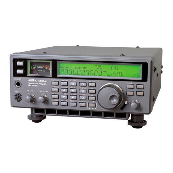
AOR AR5000 Operating Manual
Hide thumbs
Also See for AR5000:
- Command list (10 pages) ,
- Operating manual (2 pages) ,
- Quick manual (2 pages)
Table of Contents
Advertisement
Quick Links
Download this manual
See also:
Quick Manual
Contents
(1) Table of contents .......................................................................... 1
(2) Introduction ................................................................................... 2
2-1 Key information and common menus .................................. 3
2-2 Accessories supplied .......................................................... 4
(3) Major Features .............................................................................. 4
(4) Precautions ................................................................................... 4
4-1 Location .............................................................................. 4
4-2 Looking after your receiver ................................................... 5
4-3 Power requirements ............................................................ 5
4-4 Aerial (antenna) connection ................................................. 5
(5) Controls and functions ................................................................ 6
5-1 On/Off power switch ............................................................ 6
5-2 S-meter (signal strength meter) ........................................... 6
5-3 Liquid Crystal Display (LCD) ................................................ 6
5-7 Removable feet ................................................................... 9
5-8 Internal speaker .................................................................. 9
5-9 SQ - squelch control (plus RF control) ................................. 9
5-10 Volume control (AF GAIN) ................................................. 10
5-11 ACC 1 accessory number one socket ................................ 10
5-12 Headphone socket ............................................................. 10
5-13 Front panel keys ................................................................ 10
5-14 DC 12V - external power connection .................................. 15
5-15 ACC 2 (accessory 2 socket) ............................................. 15
5-16 EXT SP - external speaker output socket ........................... 16
5-17 REMOTE - RS232C computer control port ........................ 16
5-18 I.F. OUTPUT (10.7 MHz) ................................................... 16
5-19 STD IN (10 MHz) ............................................................... 16
5-20 MUTE ............................................................................... 16
5-21 ANT 2 ............................................................................... 17
5-22 ANT 1 ............................................................................... 17
(6) Basic manual operation of the receiver ..................................... 17
6-1 Switching on for the first time .............................................. 17
6-2 Changing VFO .................................................................... 17
6-3 Tuning the receiver using the rotary controls ........................ 18
6-4 Entering a frequency via the numeric keypad ....................... 18
6-5 Correction of frequency input via the numeric keypad ........... 19
6-6 Selecting tuning step (increment) ......................................... 19
6-7 Step-adjust .......................................................................... 20
6-8 FREQUENCY OFFSET ....................................................... 22
6-9 Changing receive mode (AUTOMODE) ................................ 22
6-10 IF BANDWIDTH ................................................................ 24
6-11 AF SET - (Audio characteristics) ........................................ 25
6-12 Audio tone eliminator (T-ELMT) ......................................... 27
6-13 DTMF decoder .................................................................. 28
6-14 RF Attenuator & preamplifier ............................................. 28
6-15 CONFIG menu outline of facilities ...................................... 28
6-16 CONFIG - LAMP ............................................................... 29
6-17 CONFIG menu - BEEP ..................................................... 29
.......................... 8
............................ 8
brake) ..................................... 8
6-18 CONFIG - EXTERNAL I.F. output (SDU5000) ..................... 29
6-19 CONFIG - Computer control BPS ....................................... 29
6-20 CONFIG - Advanced aerial switching .................................. 30
6-21 CONFIG - Frequency standard ............................................ 32
(7) Memory banks & channels ............................................................ 33
7-1 Storing receive data into memory - VFO mode ...................... 33
7-2 Memory recall - Recalling receive data from memory ............. 34
7-3 Transfer of memory channel to VFO ...................................... 35
7-4 Changing and deleting memory data ..................................... 35
7-5 Deleting memory channels and banks ................................... 36
(8) SCAN - scanning memory channels & banks ............................. 37
8-1 SCAN - outline introduction to facilities available ................... 37
8-2 Starting to SCAN, considerations .......................................... 37
8-3 SCANNING a memory bank ................................................. 38
8-4 Selecting a single memory bank to scan ................................ 38
8-5 Memory bank linking to scan ALL memory banks .................. 39
8-6 Specifying memory bank linking ............................................ 39
8-7 Scanning a memory bank which is not linked ........................ 39
8-8 SCAN channel PASS (lockout) .............................................. 40
8-9 Cyber Scan in SCAN mode .................................................. 41
(9) Additional SCAN facilities ............................................................. 41
9-1 SCAN - PAUSE .................................................................... 41
9-2 SCAN - DELAY .................................................................... 42
9-3 SCAN - LEVEL SQUELCH ................................................... 42
9-4 SCAN - VOICE ..................................................................... 42
9-5 SCAN - MODE (receive mode AM, FM etc) ........................... 43
(10) SELECT SCAN - special select scan list overview ................... 43
10-1 Tagging scan select channels .............................................. 43
10-2 SELECT SCAN - while in SCAN MODE .............................. 44
10-3 SELECT SCAN while in MEMORY RECALL mode ............. 44
10-4 Starting SELECT SCAN ..................................................... 44
10-5 Deleting all SELECT SCAN channels in one go ................... 44
(11) Priority operation .......................................................................... 45
11-1 Engaging PRIORITY channel .............................................. 45
11-2 Changing PRIORITY channel parameters ............................ 45
(12) SEARCH ......................................................................................... 46
12-2 Simple search (VC, VD, VE) ............................................... 47
12-3 Optimising VFO search parameters ..................................... 48
12-4 Program search banks ........................................................ 49
12-5 Starting program search ...................................................... 50
12-6 Cancelling, restarting program search ................................. 50
12-7 Programming and reprogramming SEARCH BANKS .......... 51
12-8 Deleting PROGRAM SEARCH BANKS ............................... 53
12-9 SEARCH - outline introduction to additional facilities ........... 53
12-10 Linking program search banks ........................................... 54
12-11 Linking only a few search banks ......................................... 55
12-14 PROGRAM SEARCH - PAUSE ......................................... 55
12-15 PROGRAM SEARCH - DELAY ......................................... 56
12-16 PROGRAM SEARCH - LEVEL SQUELCH ....................... 56
12-17 PROGRAM SEARCH - VOICE ......................................... 57
12-18 Cyber Search ................................................................... 57
12-19 AUTO-STORE .................................................................. 58
AR5000 OPERATING MANUAL
PAGE 1
Advertisement
Table of Contents

Related Manuals for AOR AR5000


Summary of Contents for AOR AR5000
-
Page 1: Table Of Contents
6-15 CONFIG menu outline of facilities ........28 12-17 PROGRAM SEARCH - VOICE ......... 57 6-16 CONFIG - LAMP ............... 29 12-18 Cyber Search ..............57 6-17 CONFIG menu - BEEP ............. 29 12-19 AUTO-STORE ..............58 AR5000 OPERATING MANUAL PAGE 1... -
Page 2: Introduction
(2) Introduction (13) Frequency Pass ................58 13-1 Register PASS Frequency ..........59 Thank you for purchasing the AOR AR5000 wide band all 13-2 Manually adding a PASS frequency ........59 mode receiver. The AR5000 uses the very latest NCO 13-3 Editing pass frequencies ........... -
Page 3: Key Information And Common Menus
(skipped if AUTOMODE is used) Press (skipped if AUTOMODE is used) Additional search facilities (12-14, 12-15, 12-16, 12-17, 12-19): Press Option menu (6-12, 6-13, 15-2, 16-2): Press (if DS8000 option is fitted) (if CT5000 option is fitted) AR5000 OPERATING MANUAL PAGE 3... -
Page 4: Accessories Supplied
(pre-selector) circuits Avoid strong RF fields from nearby transmitters. If in doubt, up to 1GHz. disconnect the AR5000 from the aerial and switch the set Comprehensive bandplan information specific to the target off. market area has been programmed into the AR5000... -
Page 5: Looking After Your Receiver
* For further information please refer to section 20 of this manual regarding aerial and earth systems. 4-4 Aerial (antenna) connection The AR5000 has two 50 OHM aerial input sockets fitted as standard to the rear panel. Further aerials may be connected using the optional aerial switching unit AS5000 with switching data being fed from a rear panel accessory socket (ACC 2). -
Page 6: Controls And Functions
(5) Controls and functions 5-3 Liquid Crystal Display (LCD) The AR5000 receiver is housed in a strong metal cabinet. Controls for operation are located on the front of the Display of operational information is provided via a high cabinet with connections to the rear. - Page 7 The legend “ALARM” will be displayed on the even if the frequency is still busy. LCD even when the AR5000 is switched off (as long as power is maintained to the receiver). At the prescribed 14 “VCS” is a selectable parameter (VOICE) for SCAN time, the receiver will automatically switch on.
-
Page 8: Main (Large) Rotary Tuning Control
22 “AUTO” is displayed when the receive mode selection This smaller control may be programmed in a number of is set to AUTO. In this condition the AR5000 will select different ways. It too is largely used to tune the receiver... -
Page 9: Removable Feet
5-8 Internal speaker as RF GAIN by selecting on the keypad, the The AR5000 is fitted with a lower case mounted speaker. “ -SQL” legend is removed from the LCD to confirm In order to provide best projection of audio from the operation. -
Page 10: Volume Control (Af Gain)
1.2 OHMS. When turned fully clockwise the volume is at maximum, 6 High level audio output. The AR5000 provides both when rotated fully anti-clockwise the volume is reduced high and low level audio output for feeding tape recorders to minimum. - Page 11 MODE select menu using a short cut... select - V.MODE AUTO by pressing and holding the key for more than one second. The AR5000 has a FIVE VFO system being identified “ ”, “ ”, “ ”, “...
- Page 12 Figure SIX for the numeric input of frequencies, bank, automatically after a prescribed time period of 1 to 120 channel numbers etc. minutes... useful if you go to sleep with the AR5000 as a The sequence activates the RF GAIN control bedside radio.
- Page 13 Note: If this key is accidentally pressed, it may give the 0.100 kHz (100 Hz), 0.500 kHz (500 Hz), 1.000 kHz, impression that the AR5000 is not receiving certain 5.000kHz, 6.250 kHz, 9.000 kHz, 10.000 kHz, 12.500 frequencies... so make sure you are familiar with the PASS kHz, 20.000 kHz, 25.000 kHz, 30.000 kHz, 50.000 kHz,...
- Page 14 Under this situation the on channel sensitivity will generally be reduced to once the key has been used, the AR5000 some degree, for this reason do not manually tune the microprocessor will automatically add the additional trailing preselector too far away from the start point.
-
Page 15: Rear Panel
7 No connection personal injury and fire. 8 Ground 5-15 ACC 2 (accessory 2 socket) This 8-pin miniature socket is used for connection of an optional aerial (antenna) switching unit (AS5000) so that AR5000 OPERATING MANUAL PAGE 15... -
Page 16: Ext Sp - External Speaker Output Socket
MUST be left in the mute socket for standard permits the AR5000 to be connected directly to a computer operation or the AR5000 will not receive and no audio will for hands off remote control. be heard from the speaker. -
Page 17: Ant 2
(Hz position) to ensure the receiver is in AUTO MODE. This This is the secondary aerial (antenna) input for the AR5000 places the receiver into a known state of operation ready receiver. -
Page 18: Tuning The Receiver Using The Rotary Controls
Note: If you press the VFO key for one second or longer, SEARCH will be activated. 6-3 Tuning the receiver using the rotary controls The AR5000 is now in a known state of operation ready The receiver may be tuned using the rotary tuning controls for data input. -
Page 19: Correction Of Frequency Input Via The Numeric Keypad
The any changes. If you wish to abort step size selection press AR5000 has been pre-programmed at the factory with all the bandplan data (specific to each market area) so that the AR5000 will automatically select the appropriate step In addition, unusual step sizes may be entered using the size and mode for the frequency chosen. -
Page 20: Step-Adjust
VFO mode. Alternatively press to abort entry and return 6-7 Step-adjust to VFO mode. The AR5000 provides a powerful feature to enable Select receive mode: Press the key and use accurate following of unusual bandplans. When active, to select “... - Page 21 VFO mode. Application of arithmetic for the step-adjust For those who wish further information on the mathematics involved... the AR5000 works this out for you automatically! The following examples should explain how the step-adjust works in theory.
-
Page 22: Frequency Offset
See above Example of display: (item 4) for selection of “+” or “-” offset. Note: The use of frequency offset will take the AR5000 out of automode. To reactivate automode press and hold key for more than one second, the legend “AUTO”... - Page 23 WFM - The AR5000 does not list WFM (Wide Band Frequency Modulation) as a separate mode, it is simply a product of the I.F. filter bandwidth selection. Select a wide If automode is currently in use, the legend “...
-
Page 24: If Bandwidth
This is not a criticism of the AR5000 and is applicable to particular modes require differing amounts of bandwidth ALL SSB receivers in varying degrees... the AR5000 in order to operate otherwise the receive system simply being very good. -
Page 25: Af Set - (Audio Characteristics)
6-11 AF SET - (Audio characteristics) There are four available high pass frequencies: 0.05 kHz It is possible to optimise the audio settings of the AR5000, (50 Hz), 0.02 kHz (200 Hz), 0.3kHz (300 Hz) & 0.4 kHz there are a total of 5 different settings relating to the audio (400 Hz). - Page 26 Morse code) is usually centred around a kHz <<< tone of 700 to 800 Hz. The audio stage of the AR5000 is configured to emphasise this window , however the centre frequency may be changed to suit personal preferences or specific requirements.
-
Page 27: Audio Tone Eliminator (T-Elmt)
184 ~ 196 to ensure that important radio links are in working order. 198 ~ 208 The AR5000 tone eliminator is used to eliminate many of these tones to enable the squelch to close when in scan 208 ~ 217 &... -
Page 28: Dtmf Decoder
0dB and 10dB. The “AMP” legend is always displayed. Note: The # symbol is displayed as “=“ on the AR5000 LCD. If the DTMF tone consists of more than 10 Above 1,000 MHz (1 GHz) The attenuator is disabled to characters, the LCD will scroll up the entire DTMF tone minimise signal loss through the switching unit... -
Page 29: Config - Lamp
/ external frequency reference. The AR5000 is capable of providing a 10.7 MHz I.F. output suitably wide enough to drive the optional SDU5000 spectrum display unit with a bandwidth of up to ± 5 MHz. -
Page 30: Config - Advanced Aerial Switching
“ANT ”, “ANT ” and “ANT ”. It is possible to program the AR5000 to automatically switch the aerial input used (aerials 1 & 2 at default or aerial 1, 2, 3 & 4 with the optional AS5000 aerial switching unit) depending upon receive frequency. - Page 31 Starting at AERIAL 3 channel 0 key in the lowest upper freq limit 200MHz frequency limit then key in the upper lower freq limit frequency limit upper freq limit and so on..lower freq limit upper freq limit AR5000 OPERATING MANUAL PAGE 31...
-
Page 32: Config - Frequency Standard
6-21 CONFIG - Frequency standard data already programmed using the key until the The AR5000 is fitted with a 12.8 MHz internal TCXO legend “- - - - - - - - - -” is displayed. (Temperature Compensated Crystal Oscillator) as standard to ensure the ultimate in frequency precision. -
Page 33: Memory Banks & Channels
The stored data may be quickly and easily recalled, changed or deleted using the memory recall and delete facilities. The flashing legend “M” for memory also indicates that a memory location is being displayed (rather than a search AR5000 OPERATING MANUAL PAGE 33... -
Page 34: Memory Recall - Recalling Receive Data From Memory
It is possible to add text at present at this time. a later time. The AR5000 will monitor whatever memory channel first appears when you enter memory recall mode. To aid text entry, a decimal “.” is displayed to the right of the text entry point (initially close to the left of the LCD). -
Page 35: Transfer Of Memory Channel To Vfo
7-1 of this manual. flashing. The legend “- - >” and “< - - “ confirms that memory location 123 is to be over-written with data. AR5000 OPERATING MANUAL PAGE 35... -
Page 36: Deleting Memory Channels And Banks
Deleting individual memory channels First place the AR5000 into memory recall mode. Switch on the receiver and press the key once (unless it is in SCAN mode in which case you should press The legend “- -”... -
Page 37: Scan - Scanning Memory Channels & Banks
& banks frequencies found while conducting a SEARCH may be automatically written to memory (see SEARCH at section The AR5000 has a SCAN MODE whereby the contents 12 with auto-store at section 12-19). This is a useful tool stored MEMORY... -
Page 38: Scanning A Memory Bank
Note: If text has not been stored in the memory channels and TEXT DISPLAY has been selected, the AR5000 will halt on busy channels but no frequency or text will be displayed... this can be confusing at first. To restore the... -
Page 39: Memory Bank Linking To Scan All Memory Banks
BANK LINK programming. To SCAN any deselected bank simply rotate the The AR5000 will use the settings of whichever bank link while scanning until the desired scan bank number is identifier (profile number) is displayed when the bank link displayed in the top right of the LCD. -
Page 40: Scan Channel Pass (Lockout)
8-8 SCAN channel PASS (lockout) displayed while in memory recall mode whether the “PASS” indicator is shown or not. Should the AR5000 stop on an active channel while scanning and for some reason you do not wish to monitor Deleting memory pass channels... -
Page 41: Cyber Scan In Scan Mode
(which is capable of scanning about 25 memory channels per second), typically the speed accept the entry and the AR5000 will revert to SCAN, increases to about 45 channels per second. SEARCH or VFO mode depending upon which was previously in use. -
Page 42: Scan - Delay
Note: It is possible that false signal levels may upset the operation of scan LEVEL SQUELCH due to local noise or the close proximity of computer systems. Number 1 instructs the AR5000 to react to very weak signals while a Either use the to change the value. -
Page 43: Scan - Mode (Receive Mode Am, Fm Etc)
. The legend key acts as a short cut to “ ”. “ ” is added before the memory bank number to show that the channel has been added to the select scan list. AR5000 OPERATING MANUAL PAGE 43... -
Page 44: Select Scan - While In Scan Mode
(tagging and un-tagging) When the memory channel has been tagged using the While the receiver is scanning, the AR5000 will stop on sequence , the legend “ ” will be displayed active frequencies and you will soon realise that some next to the bank number of the chosen memory channel are interesting and some uninteresting . -
Page 45: Priority Operation
The priority checking is accomplished by momentarily tuning the receive circuit to the priority frequency to see if 11-2 Changing PRIORITY channel it is active . If activity is found, the AR5000 will remain on parameters the active frequency until the signal disappears. If no activity is detected, the receiver returns to the VFO The default channel used for PRIORITY is “... -
Page 46: Search
The AR5000 is equipped with various SEARCH modes whereby an upper and lower frequency limit may be Program search (bank search) - Search banks defined and the AR5000 instructed to look for activity on 00 ~ 19 all frequencies in predetermined step size in an upward or downward direction. -
Page 47: Simple Search (Vc, Vd, Ve)
“AUTO” legend is displayed to ensure the AR5000 search and restart the process. is in AUTOMODE (as each VFO can retain different mode information). -
Page 48: Optimising Vfo Search Parameters
The process will halt when a busy frequency is located, (at default the delay is two seconds after the The DELAY parameter affects the time the AR5000 will transmission clears) then resume searching again when remain on an active frequency in VFO search once the the frequency is clear. -
Page 49: Program Search Banks
Either use the to change the value. A value of 1 instructs the AR5000 to react to very weak key may be used as a short cut to OFF. signal while a value of 255 instructs the AR5000 to react ONLY to strong signals. -
Page 50: Starting Program Search
Banks “ ” to “ ” just need the last digit keyed, Saving busy frequencies into memory the preceding “ ” is automatically added by the AR5000 microprocessor. Banks “ ” to “ ” require the entry of It is possible to save interesting frequencies into memory. -
Page 51: Programming And Reprogramming Search Banks
(“ ”) and lower (“ ”) frequency limits would alternatively be to AUTOMODE. displayed to warn that data was about to be over-written. AR5000 OPERATING MANUAL PAGE 51... - Page 52 05. This can be useful to assist identification of banks when the AR5000 in used in TEXT Auto aerial switching: To enable the fastest search rates, display mode but the input of text is not mandatory. Should...
-
Page 53: Deleting Program Search Banks
At default when shipped from the factory, the AR5000 To start searching program search bank 05 (or whatever will remain on an active frequency until the received signal bank was last selected) simply press (providing disappears and the squelch closes. -
Page 54: Linking Program Search Banks
12-13 of this manual for further information. Selecting different favourite bank link identifiers The AR5000 will use the settings of whichever bank link There are ten possible PROFILES for BANK LINK which identifier is displayed when the bank link menu is accessed... -
Page 55: Linking Only A Few Search Banks
2.0s, as in the DELAY menu). When you are happy with the changes press to accept the changes and the AR5000 will revert to SCAN, SEARCH or VFO mode depending upon which Next time the AR5000 is returned to SEARCH MODE, was previously in use. -
Page 56: Program Search - Delay
Note: It is possible that false signal levels may upset the operation of search LEVEL SQUELCH due to local noise or the close proximity of computer systems. A value of 1 instructs the AR5000 to react to very weak Either use the to change the value. -
Page 57: Program Search - Voice
If nothing were displayed to show that Cyber Search was in operation and no transmissions were encountered, the AR5000 may otherwise look like it was doing nothing. The legend “*” positioned to the right of the word “ ”... -
Page 58: Auto-Store
Deleting ALL channels from memory bank “ ” automatically to memory bank “ ” by entering MEMORY before using AUTO-STORE RECALL MODE. Ensure the AR5000 is in VFO or memory recall mode, if First place the AR5000 into memory recall mode by in doubt press pressing the... -
Page 59: Register Pass Frequency
VFO (or manual search or simple search) mode. Rotate the to select the required bank number (00 ~ 19 or VFO). To accept the input and complete the process, press in either of the two menus. AR5000 OPERATING MANUAL PAGE 59... -
Page 60: Editing Pass Frequencies
” will be displayed with an identifying bank number or legend “ ” to the right depending on whether the AR5000 is currently in program search mode (in which case the current bank number will be displayed) or VFO (or manual... -
Page 61: Deleting Complete Banks Of Pass Frequencies
13-4 of this manual)..especially if you have previously from 00-00-00 hrs. registered 100 pass frequencies in a bank. Ensure the AR5000 is in VFO or memory recall mode, if 14-1 Displaying the clock in doubt press To display the real time clock, press . -
Page 62: Setting Time
However for accurate setting, display clock 1 again. Press and hold the key for more than one second to scroll passed “ ” then press the key again for more than one second to display clock 1. PAGE 62 AR5000 OPERATING MANUAL... -
Page 63: Alarm Clock
Alarm BEEP During ALARM BEEP mode, the AR5000 will power-up at the pre-set time causing the beep sounder to activate (repeated three beeps) at the pre-set volume level. This is useful as an (expensive!) alarm clock when you don’t want to miss an important broadcast or event. -
Page 64: Alarm Activation
14-5 ALARM activation Once the alarm has been activated the “ALARM” legend will be displayed on the top line of the LCD. The AR5000 will switch-on automatically once per day (presuming the receiver had been switched off) on a daily basis at the... -
Page 65: Option - Descrambler (Voice Inverter) - Ds8000
15-1 Descrambler installation 2 “ ” legends flash on the LCD prompting for input Only the upper case of the AR5000 needs to be removed of sleep time. The may be rotated when installing the optional DS8000 board. Switch the to make selection between 1 and 120 minutes, the default receiver off and unplug the power cord. -
Page 66: Descrambler Operation
Assuming that power is connected to the AR5000 and To increase versatility different CTCSS tones may be programmed into each memory and VFO. the power switch is currently OFF, press and hold key then power up the receiver by pressing and... -
Page 67: Installation Of The Ct5000
16-1 Installation of the CT5000 key then power up the receiver by pressing and releasing the switch while still holding the Only the upper case of the AR5000 needs to be removed key. Now release the key. The “ ” tone when installing the optional CT5000 board. -
Page 68: Ctcss Squelch
17-1 Fitting the optional 500 Hz filter received a strong signal (which does not carry the selected CTCSS frequency). Only the upper case of the AR5000 needs to be removed when installing optional filters. Switch the receiver off and 1 To access the CTCSS menu press . -
Page 69: Installation Of Other Filters
3 Pull the PCB towards the front panel and lift it as shown 17-2 Installation of other filters in the diagram. Consult your AOR dealer if you wish to install other filters such as 2.5 kHz and 5.5 kHz. To add these substitute filters, the standard ceramic filters must be replaced, this requires good quality tools and technical skill. -
Page 70: Trouble Shooting - Microprocessor Reset
The reset switch is located at reset the top of the slot about 10mm behind the front panel. Should the AR5000 fail to operate correctly, refer to the following instructions before contacting your AOR dealer for support. -
Page 71: Af.set Int/Ext
18-4 AF.SET INT/EXT Power-On Add descrambler entry to the option menu after fitting the The AR5000 may have become confused about the status optional DS8000 board. of AUDIO INTERNAL / EXTERNAL. Reaffirm the setup. 1 Press to access the audio setup menu. -
Page 72: Optional Accessories
Computer control software LA320 loop aerial A hands off IBM-PC WINDOWS computer program is planned to control the AR5000 via the rear panel remote Desktop active loop aerial for portable connector. A separate serial connecting lead will also be operation away from a base aerial such required to connect to your computer. - Page 73 OHM coaxial cable. In this instance the path of feeder is i.e. For 14.2 MHz unimportant and chances of noise entering the aerial system reduced. The 50 OHM aerial input of the AR5000 is ideally suited for connection to a magnetic balun. ------- = 5.28 metres (i.e.
- Page 74 Short wave desktop loop aerials have the advantage of called the ABF125. This will help minimise the possible small size (such as the AOR LA320). They too have tuning effects of breakthrough when listening to VHF airband in controls to reject unwanted signals. As the loop is within...
-
Page 75: Propagation - Short Wave Bands
For instance the MUF (Maximum Usable Frequency) is the D layer dissipates, medium and low frequency often stated for a path between two locations. Choosing transmissions may propagate over much greater a frequency above the MUF will not produce results as distances. AR5000 OPERATING MANUAL PAGE 75... -
Page 76: Specification
10.7 MHz with maximum ± 5 continuous development of the product E&OE. MHz bandwidth Manual version 1.0. External reference 10.0 MHz input Mute Phono/RCA socket CMOS input pull-up to 5V @ 100k OHMS Operating temp. 0° to +50° C PAGE 76 AR5000 OPERATING MANUAL... - Page 77 AR5000 OPERATING MANUAL PAGE 77...
Need help?
Do you have a question about the AR5000 and is the answer not in the manual?
Questions and answers
Sir can I Reset the settings of AR 5000 pl send me
To reset the settings of the AOR AR5000, perform a CPU SOFT RESET:
1. Switch off the receiver (unplug the power cord if needed).
2. Press and hold the "CLR" key.
3. While holding "CLR", switch the receiver back on.
4. Keep holding "CLR" until the default frequency/text display appears, then release the key.
This resets the VFO to default parameters and clears all bank link information. Default settings include:
- Frequency: 128.900 MHz
- Mode: AM
- Tuning Step: 25 kHz
- IFBW: 6.0 kHz
- Attenuator: 00 dB
This answer is automatically generated
Sir I have AR 5000 Signal received but Background Noice is very high
To reduce background noise on the AOR AR5000, try the following:
1. For early AR5000 units: Add a 22-ohm resistor in the IF chain to address noise and instability in the 10.7 MHz section.
2. Shielding: Install a small grounded shield around Q10 (FSX52WF) on the RF board to reduce oscillation between 400 MHz and 1 GHz.
3. Adjust RF Gain and AGC: Reducing RF gain and adjusting AGC settings can help minimize noise, especially after a strong signal ends.
4. Antenna and grounding: Use a properly grounded antenna to reduce external noise sources.
These steps target known noise issues in early AR5000 units and general noise reduction.
This answer is automatically generated