Table of Contents
Advertisement
1 Introduction
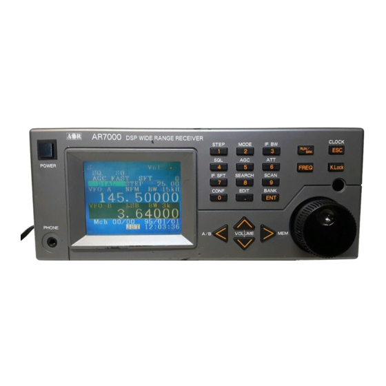
Thank you for purchasing the AR7000 wide band all mode receiver. The AR7000 is
designed using DSP (Digital Signal Processing) technology to ensure the highest
levels of performance and reliability. To get the best possible results from your
AR7000 we recommended that you read this manual and familiarise yourself with the
receiver. Although carefully designed, this receiver (like all receivers) suffers from a
degree of internal noises known as spurii which are a product of the receiver's
circuitry and do not represent a fault. Apparent faults may be due to accidental mis-
operation of the receiver, if you think there is a problem, carefully read all of the
manual before deciding to return the receiver for repair.
Every effort has been made to make this manual correct and up to date. Due to
continuous development of the receiver and by error or omission anomalies may be
found and this is acknowledged.
© This manual is protected by copyright AOR Ltd 1998. No information contained in
this manual may be copied or transferred by any means without the prior written
consent of AOR Ltd. AOR and the AOR logo are trade marks of AOR Ltd. All other
trade marks and names acknowledged. E&OE
2 Standard supplied accessories
1 x Power supply (a.c. to d.c., input voltage dependant on market)
1 x Infrared remote controller
1 x Operating manual (this booklet)
3 For your safety
There are no internal operator adjustments. In the unlikely event of servicing being
required, please contact your dealer for technical assistance.
The AR7000 is designed for operation from its supplied a.c.-to-d.c. adapter.
Operation is possible from a d.c. supply of 12 to 14V, which should be able to supply
up to 2.0A. Never connect the AR7000 directly to the a.c. supply.
Do not use or leave the receiver in direct sunlight (especially the LCD). It is best to
avoid locations where excessive heat, humidity, dust and vibration are expected.
Always treat the receiver with care. Take care to avoid spillage or leakage of liquids
into the receiver and a.c. power supply. Special care should be taken to avoid liquid
entering around the controls, through the speaker grille or via the connection jacks.
If fitting a separate external earth rod, consider the implications carefully if your
buildings' a.c. supply uses a Protective Multiple Earth (PME) system. If in doubt
consult an expert electrician. Never earth to a gas pipe!
The AR7000 has a single BNC aerial socket for all frequencies. This socket is
intended for connection of a 50 OHM (unbalanced) coaxial fed aerial such as a
discone, dipole, unipole, yagi etc. When sighting the aerial, avoid power cables. A
telescopic whip may be connected to this socket for local monitoring.
Advertisement
Table of Contents

Related Manuals for AOR AR7000


Summary of Contents for AOR AR7000
- Page 1 © This manual is protected by copyright AOR Ltd 1998. No information contained in this manual may be copied or transferred by any means without the prior written consent of AOR Ltd. AOR and the AOR logo are trade marks of AOR Ltd. All other trade marks and names acknowledged. E&OE 2 Standard supplied accessories 1 x Power supply (a.c.
-
Page 2: Table Of Contents
8.2 Video format switch......….. 11 8.3 Connection of the aerial....…. 11 8.4 Power it up.........………. 11 9 Keyboard (basic operations)..... 12 AR7000 Basic operation......… 13 * Understanding the basic operation..... 14 # Basic operating modes......…. 14 # Audio volume.........……… 14 # Key lock........…………... - Page 3 2.6 Transfer data from dial to memory..29 3 Memory mode........…… 30 3.1 Display........………. 30 3.2 Memory channel......… 3.3 Memory bank........…... 30 3.4 Transfer data from memory to dial..3.5 Memory data edit......…. 4 Search and Scan mode......38 4.1 Type of scan/search and definitions..38 4.2 Display and Run/Brk......….
-
Page 4: Care & Maintenance
AR7000 (for each world market area). Although the AR7000 has no special rear panel socket for a connection of an RF earth, a separate earth may be connected to the chassis ground connectors (RS232, video, audio, BNC) then on to a water pipe, central heating system radiator or external earth rod. -
Page 5: Front Panel
Press this switch to power the radio on/off. In addition the separate infrared remote controller (supplied) will enable the AR7000 to be switched off. Note: The AR7000 may be switched off and on via the infrared remote only if the AR7000 mechanical front panel switch remains depressed. - Page 6 {figure 2} 7.2.1 AUX connector This 8-pin 270º DIN socket provides output for audio, squelch switching, etc. Refer to section 10 of this manual for pin-out details. 7.2.2 Video output switch This slide switch selects the video format of either PAL or NTSC. The default position is NTSC.
-
Page 7: Before The Set Is Switched On
Make sure that all necessary connections are made, and double check that the power supply voltage/polarity are correct. Press the front panel power switch to switch the AR7000 on. The dial mode set-up will be displayed on the LCD following the CPU initialising. -
Page 8: Understanding The Basic Operation
3. Press [ENT] key to confirm the entry. Understanding the basic operation Basic operating modes The AR7000 is equipped with the 2 dial modes (VFO-A, VFO-B) and one memory mode. Push the [ key to scroll from VFO-A to VFO-B to Memory back to VFO-A... -
Page 9: A Dial Mode
{figure 10} A Dial mode The AR7000 is equipped with the 2 dial modes, VFO-A and VFO-B. You can manually select/enter the receive frequency, receive mode, etc. VFO is a historical term for Variable Frequency Oscillator, today it is used to describe a facility which stores frequency &... -
Page 10: Recall The Memory Channel
{figure 13} B Memory mode The AR7000 is equipped with a total of 1500 memory channels (100 ch x 15 banks). Each memory channel can be given an alpha-numeric ident of up to 7 letters for ease of identification, the ident is displayed to the upper left of the frequency (under the legend “MEMORY”). -
Page 11: Manual Search
Manual search and Program search. C-1 Manual search When the AR7000 is in the “DIAL” mode (either VFO-A or VFO-B on the upper line of the large frequency readout) the manual search can be used. 1. Push the [RUN/BRK] key while in dial mode to initiate the manual search. -
Page 12: D Scan Mode
Remember, the squelch must be advanced high enough to cancel the background noise or the search process will not progress as the AR7000 will think that it has found a busy frequency. Press [SQL] and rotate the main dial clockwise until background noise in cancelled then press [ENT] to accept the new value. -
Page 13: Program Scan
Remember, the squelch must be advanced high enough to cancel the background noise or the scan process will not progress as the AR7000 will think that it has found a busy channel. Press [SQL] and rotate the main dial clockwise until background noise in cancelled then press [ENT] to accept the new value. -
Page 14: Ar7000 Reference Manual
6. Push the [ESC] key to go back to the operating mode in use prior to program scan selection. AR7000 Reference manual 1. Basic operation 1.1 Selection of the basic operating mode Push the [ key to advance the operating mode clockwise, VFO-A to VFO-B to MEMORY to VFO-A..., push the [... -
Page 15: Agc Setting
{figure 34} 1.6 ATT (Attenuator) setting The AR7000 is equipped with a 10dB RF attenuator, this can be useful for reducing the effect of strong local signals which otherwise may lead to “mixing” inside the receiver’s circuitry (common to all receivers). Each press of the [ATT] key will toggle the attenuator ON and OFF. -
Page 16: Dial Mode
Clockwise rotation increases frequency while ant- clockwise rotation decreases frequency. 2.3 Selection of frequency step The step size cannot be altered while the AR7000 is in AUTO MODE (while the legend “AUT” displayed on the LCD), select another receive mode then press the [STEP] key. -
Page 17: Selection Of Receive Mode
(10 Hz) and 1000 kHz (1 MHz). The back space key [ ] will act as delete key if a mistake is made. When AUTO MODE is selected, the step size is selected automatically by the AR7000 CPU appropriate to the market area, this is taken from a detailed bandplan entered into the AR7000 during manufacture. {figure 40} 2.4 Selection of receive mode... -
Page 18: Transfer Data From Dial To Memory
3 Memory mode The AR7000 is equipped with a total of 1500 memory channels arranged as 15 memory banks 0 to 14, each containing 100 channels numbered 00 to 99. Each memory channel can be tagged with a text ident of up to seven characters. -
Page 19: Memory Channel
{figure 45} 3.2 Memory channel In the memory channel mode, either rotate the main dial to select the memory channel or use the [ keys. Memory channels with no valid data will be ignored (skipped = not shown). 3.3 Memory bank In the memory mode, press the [BANK] key. - Page 20 Press [ENT] to confirm your selection. When AUT has been selected as the current receive mode, IF-BW will be automatically selected by the AR7000 CPU mapped band plan, for this reason you cannot change the IF-BW when AUT receive mode is selected, the IF-BW will display “- - - -“...
- Page 21 {figure 54} The Name Edit screen will be displayed. Your desired text ident may now be entered or edited. Use the [ ] and [ ] keys to select character line number, use the main dial to move along each line, use the [ keys to move along the seven character text ident, use the [ENT] key to accept the input for each character.
- Page 22 {figure 60} B Selection of distant memory (destination) Press the [ENT] key when the cursor “>” is next to the “Dist”. The channel number of the distant memory will reverse to a negative image. Press the [ keys to toggle between channel number and bank number. Rotate the main dial to select the desired memory channel and bank number for the distant memory channel.
- Page 23 B Selection of distant memory channel Press the [ENT] key when the cursor “>” is next to “Dist”. The channel number of the distant memory will reverse to a negative image. Press the [ keys to toggle between channel number and bank number. Rotate the main dial to select the desired memory channel and bank number for the distant memory channel.
-
Page 24: Search And Scan Mode
between channel number and bank number. Rotate the main dial to select the desired memory channel and bank number for the distant memory channel. Press [ENT] {figure 73} C Executing the swap Now that both source memory and distant memory channel have been selected, press the [ ] and [ ] keys to move the cursor “>”... -
Page 25: Display And Run/Brk
The AR7000 steps through the spectrum using the selected mode and step size (including automatic selection using the automode bandplan data programmed into the AR7000 CPU). -
Page 26: Manual Search
The squelch threshold is shown as a light blue horizontal line, when temporarily stopped, a vertical dark cursor bar indicates current receive frequency. The larger the signal received, the higher the green bars of spectrum analysis, however, there is no way of showing real time signal strength on the spectrum display (refer to the s- meter in the top left corner of the LCD for current signal strength). -
Page 27: Program Search
4.4.3 Terminate the manual scan Push the [ENT] key while the scan is in progress. The AR7000 will revert to memory mode still retaining the current memory channel. Push the [ESC] key to revert to memory mode with the previously selected memory channel displayed (before the scan first began). - Page 28 {figure 85} When an active signal has been found the program search will stop. The search will resume when the active signal has disappeared and squelch closes, or in case of time controlled search, when a pre-determined time has elapsed. Rotate the main dial or use the [ keys to force the search to resume, you cannot reverse the direction of program search as it is defined in the programming menu.
- Page 29 key to accept the input for each character. Other options include Insert, Delete, Space and Quit. Refer to section 7 of this manual for further details. {figure 87} C Stop time Push the [ENT] key when the cursor is placed alongside the item “Stop Time”. {figure 88} Rotate the main dial or push the [ keys to select the desired stop time in...
- Page 30 Note: When inputting start and stop frequencies, the AR7000 automatically assigns the lower frequency to the START and upper frequency to the STOP regardless of which order then are entered. F End frequency Push the [ENT] key when the cursor is placed alongside the item “Stop”. Enter the desired stop frequency followed by [ENT].
-
Page 31: Program Scan
O N : When active signals above the squelch threshold have been received, such signals will be automatically stored in the empty channels of the designated memory bank. When the memory bank becomes full, the auto store action will become invalid, the search process will carry on regardless. - Page 32 Having selected the desired program scan number, push the [RUN/BRK] key to start the program scan. {figure 99} The scan process will temporarily stop when an active signal above the squelch threshold has been received. The scan process will resume when such signal has disappeared.
- Page 33 C Stop time Push the [ENT] key when the cursor is placed alongside the item “Stop Time”. Rotate the main dial or push the [ keys to select the desired stop time in seconds followed by [ENT]. {figure 102} SQ : The program scan will stop as long as the received signal stays above the squelch threshold, scan will resume once the signal drops below squelch threshold and the squelch closes.
-
Page 34: Search Pass Bank
5 Search pass/bank The AR7000 has a PASS facility which enables unwanted busy frequencies to be skipped during the scan and search processes. 5.1 Common pass bank Memory bank number 14 has been assigned the special status of PASS BANK. -
Page 35: Clock
6.2 Time The AR7000 is equipped with one main clock plus four sub-clocks. Push the [ENT] key when the cursor is placed alongside the item “Clock Setup”. Items relating to the MAIN clock are prefixed “M” and the SUB-clock are prefixed “S”. -
Page 36: Timer
-24 and 24 hours, 0 being the current time zone of the main clock), followed by [ENT]. The local time and date is calculated by the AR7000 and displayed in green in the lower half of the LCD. - Page 37 The AR7000 front panel power switch must remain depressed and d.c. power applied to the radio at all times while the timer is armed. B Setting the timer for switch-off 1. In the timer selection menu, select the date the AR7000 is to be switched off.
-
Page 38: Delay
3. Select the “Operation” item and choose “POWOFF” followed by [ENT]. 4. The AR7000 will remain active until the preset date and time has arrived then will automatically switch off. There is no need to move the cursor to the “power Off” item, simply carry on using the AR7000 as usual. -
Page 39: Priority
1 second. Select OFF if the priority facility is not required. The AR7000 will check for activity on the priority channel every few seconds as set in priority time (unless disabled by selecting OFF). If a transmission is encountered on the priority channel, the AR7000 will monitor the traffic. -
Page 40: Av Output
Push the [ESC] key at any stage to cancel the sequence returning to whatever menu was in use before the name editor was selected. Other options include Insert, Delete, and Space. 8 AV output The AR7000 can be connected with external video monitor or audio equipment via these sockets. -
Page 41: Video Output
The AR7000 can be operated via the supplied infrared remote controller. Aim the front of the remote at the front panel IR sensor to the AR7000. Most IR keys mimic those of the AR7000 and menus. The IR [POWER] key is valid only when the power... -
Page 42: Specification
check the condition of the batteries regularly to avoid damage due to leakage from exhausted batteries. 12 Reference data 12.1 Specification Frequency range 100kHz - 2000MHz Receive mode FM (W), FM (N), AM, CW, USB, LSB Receiver circuitry Triple superheterodyne & digital conversion IF frequency 1st=275.4MHz,782.28MHz, 2nd=45MHz, 3rd=10.7MHz... -
Page 43: Trouble Shooting
12.2 memory channel default data The AR7000 memory banks may contain data for test purposes during manufacture of the receiver. 12.3 Trouble shooting 1. No operation Check that power is connected to the AR7000 and the power switch is on (depressed). 2. No display... -
Page 44: Optional Accessories
In the case of the infrared controller, ensure that the batteries are in good condition and the front on the controller is pointed directly at the AR7000 IR front panel sensor. 4. Poor performance... -
Page 45: After Sales Service
12.5 After sales service There are no user serviceable parts inside the AR7000. In the unlikely event of failure, first check through the suggestions listed in section 12.3 of this manual. If the problem persists, please contact your supplier who will advise you of the after sales...
Need help?
Do you have a question about the AR7000 and is the answer not in the manual?
Questions and answers