Table of Contents
Advertisement
Advertisement
Table of Contents
Troubleshooting

Related Manuals for Furuno FA-50


Summary of Contents for Furuno FA-50
- Page 1 www.furuno.co.jp...
- Page 2 • Store this manual in a convenient place for future reference. • FURUNO will assume no responsibility for the damage caused by improper use or modification of the equipment (including software) by an unauthorized agent or a third party.
-
Page 3: Safety Instructions
WARNING something is dropped into the Do not remove these labels. If a label is missing equipment or illegible, contact a FURUNO agent or dealer the equipment is emitting smoke or about replacement. is on fire the equipment is emitting strange... - Page 4 Steering compass compass Do not install the equipment where it may get wet from rain or water splash. FA-50 0.30 m 0.30 m Water in the equipment can result in fire, electrical shock or damage to the equipment. Be sure that the power supply is compatible with the voltage rating of the equipment.
-
Page 5: Table Of Contents
TABLE OF CONTENTS FOREWORD ......................v SYSTEM CONFIGURATION................vii SYSTEM OVERVIEW..................viii 1. INSTALLATION ....................1 1.1 Equipment Lists ........................1 1.2 AIS transponder FA-50 .......................2 1.3 Whip Antenna ........................3 1.4 GPS Antenna........................4 1.5 GPS/VHF Combined Antenna ....................6 1.6 Power Supply (option) ......................8 1.7 Wiring ..........................9 1.8 Setting Adjustments...................... -
Page 6: Foreword
FOREWORD A Word to the Owner of the FA-50 Congratulations on your choice of the FURUNO FA-50 AIS Transponder. We are con- fident you will see why the FURUNO name has become synonymous with quality and reliability. For over 50 years FURUNO Electric Company has enjoyed an enviable reputation for quality marine electronics equipment. - Page 7 Interfaces for radar, PC for future networking expansion • GPS/VHF combined antenna for easy installation available • Built-in GPS receiver for position-fixing device Program Version Item Program No. Version No. Date FA-50 AIS Transponder Main Program xxx July 2007 **: Minor change...
-
Page 8: System Configuration
FR-8xx2 SERIES IF-1500AIS : Standard supply : Optional supply *Usaually FA-50 uses the internal GPS. When connecting the : Local supply external GPS, use one which satisfies the followings. 1) Outputs DTM sentence (WGS-84 can be chosen.) 2) Outputs GBS sentence. -
Page 9: System Overview
SYSTEM OVERVIEW System overview The Automatic Identification System (AIS) was originally developed to aid the Vessel Traffic Services (VTS) by use of a VHF transponder working on DIgital Selective Call (DSC) at VHF CH70, and is still in use along the UL coastal areas and others. Some time later the IMO developed a Universal AIS using the new sophisticated technology called Carrier-Sence Time Division Multiple Access (CSTDMA) based on a VHF Data Link (VDL). - Page 10 The Officer of the Watch (OOW) should always be aware that other ships, and in par- ticular leisure craft, fishing boats and warships, and some coastal shore stations (in- cluding Vessel Traffic Service centers) might not be fitted with AIS. The OOW should also be aware that AIS fitted on other ships as a mandatory carriage requirement might be switched off by the master if its use might compromise the se- curity of the vessel.
-
Page 11: Installation
INSTALLATION Equipment Lists Standard supply Name Type Code No. Remarks AIS Transponder FA-50-E GPS/VHF combined GVA-100 Select one. antenna GPS Antenna GPA-017S 1 set (Select one) GPA017 1 set Spare parts 1 set Fuse, FGB0-A 4A AC125V Accessories 1 set... -
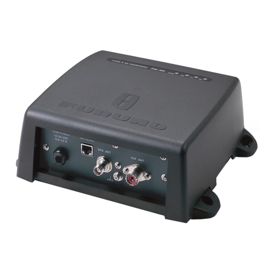
Page 12: Ais Transponder Fa-50
• Keep the unit away from electromagnetic field-generating equipment such as motors and generators. • A magnetic compass will be affected if the FA-50 is placed too close to it. Observe the compass safe distances noted in the safety instructions to prevent disturbance to the magnetic compass. -
Page 13: Whip Antenna
10 meters. • Install the VHF whip antenna (option) referring to the outline drawing at the back of this manual. Separate this antenna from other VHF radiotelephone antennas as shown below to prevent interference to the FA-50. Other VHF whip antenna... -
Page 14: Gps Antenna
Antenna cable set CP20-02700 Conversion Antenna Unit : Connector Cable Assy. NJ-JP-3DXV-1 0.6m Antenna Cable FA-50 TNCP-NJ Fabricate locally. (See next page.) N-P-8DFB • Waterproofing connector Wrap connector with vulcanizing tape and then vinyl tape. Bind the tape end with a cable-tie. - Page 15 How to attach the connector N-P-8DFB for cable 8D-FB-CV Dimensions in millimeters. Outer Sheath Armor Inner Sheath Shield Remove outer sheath and armor by the dimensions shown left. Expose inner sheath and shield by the dimensions shown left. Cover with heat-shrink tubing and heat. Cut off insulator and core by 10mm.
-
Page 16: Gps/Vhf Combined Antenna
GPS satel- lite signal if the water freezes. Outdoor Indoor Distributor DB-1 AIS Transponder FA-50 N-P-8DFB N-P-8DFB RG-10U/Y Installation overview of GPS/VHF combined antenna Mounting procedure 1. Dismount the bottom cover, cut the cable-tie inside the unit and take out the coax- ial connector attached to the combined box. - Page 17 Whip antenna fixture Loosen four screws. (M5x16) Antenna fixing bracket Combined box Bottom cover GPS/VHF Combined antenna The top of the stanchion comes into contact with the flange. Stanchion...
-
Page 18: Power Supply (Option)
Installing distributor unit DB-1 The length of the cable between the distributor unit and transponder unit is 1 m so lo- cate the distributor unit within 1 m from the transponder unit. Fix the distributor unit on the bulkhead, facing the cable entrance downward. Remove the lid of the distributor unit and secure the unit with two self-tapping screws. -
Page 19: Wiring
Wiring Connect power source, LAN cable, VHF antenna and ground wire as shown below. GPS/VHF Conbined GPS Antenna Antenna GVA-100 GPA-017/S 150M-W2VN or FAB-151D Either one 0.8 m 0.6 m Distributor unit DB-1 RG-10U/Y (8D-FB-CV for more than 20 m) Attached to Distributor RG-10U/Y (approx. - Page 20 Coupling shield ring Solder here. Connection of AIS viewer (FAISPC-MX) The AIS viewer may be connected to the FA-50 directly, or to both FA-50 and NavNet vx2. See the figure below for connection examples. Data sentences VDM, VDO FA-50 FAISPC-MX...
-
Page 21: Setting Adjustments
PC. 1.8.1 COM Port Setup, Network Setup NOTICE: Only one FA-50 may be connected to the network. Start up 1. Start up the PC and enter IP address and subnet mask. 1) Right-click My Network and Properties. - Page 22 IEC61162+ P-sentence: Transmit and receive IEC61162+P sentences format data via COM port. Off: FA-50 transmits no data. With the radio buttons at RX Speed, choose how RX speed is regulated, Auto or Manual. For manual, choose speed from the drop-down list.
- Page 23 Do you want to restart your FA-50 now? (It will take about 1 minute to restart your FA-50). 18.Click the Yes button to restart. "ER" LED on the FA-50 lights. After the LED goes off access is given. 19.The message “Please close the window.” appears. Close the browser.
- Page 24 24.Enter call sign, using seven alphanumeric characters. 25.Set Internal/External antenna positions as follows: 1) Enter distance for for location “A” of FA-50 GPS antenna. A: Distance from bow to GPS antenna position, setting range: 0-511 m 2) Enter distance for location B, C and D similar to how you did for “A” above.
- Page 25 26.Click the down-allow button for Ship Type to show the option window, and then choose a ship type. (WOIG: Wing in ground, HSC: High speed craft) 27.After finishing all settings, Click the OK button.
-
Page 26: Operation
OPERATION AIS Transponder FA-50 The FA-50 has no power switch. Power is fed from the ship’s switchboard, and a pow- er switch on the switchboard turns the FA-50 on or off. When powered, the PWR LED (green) on the cover lights. The three other LEDs on the cover flash or light with equip- ment state. -
Page 27: Messages
Messages 2.2.1 Sending a message 14 pre-difined messages (maximum 16 characters for each message) are stored in the Send Mes- sage screen. You can send a message among from these once in a minute. 1. Click Message on the main menu. 2. -
Page 28: Own Vessel Data Display
For detailed information about a messgae, click appropriate “Detail” to show the RX Log Detail screen. Own Vessel Data Display The Own Vessel Data display shows your ship’s MMSI No., RX channel Nos., and channel selection method. 1. Show the main menu. 2. - Page 29 Description of own vessel data MMSI: MMSI number (nine-digit number). Ship Name: Ship’s name (20 characters) Call Sign: Call signe (7 characters) Internal/External Antenna Position: Shows antenna posiiton. Ship Type: The ship type is shown by a digit number. Cargo Type: Choose the cargo type as below. 1) Click the Cargo Type Edit button to show the Cargo Type screen.
-
Page 30: Alarm Status
Alarm Status The alarm status log shows the latest 25 dates and times alarms were violated. Click “Alarm Status” on the main menu to show the alarm status log. Description of Alarm Status indications Alarm Status Indication Meaning TX malfunction (and Error LED lights.) TDMA RX1 Board trouble. -
Page 31: Sensor Status
Sensor Status The sensor status display provides information about sensors connected to the FA-50. 1. Show the main menu. 2. Click Sensor Status. The illustration below shows typical sensor status indications. Description of sensor status indications Indication Meaning Remarks DGPS in use... -
Page 32: Maintenance, Troubleshooting
MAINTENANCE, TROUBLESHOOTING WARNING NOTICE Do not open the equipment Do not apply paint, anti-corrosive sealant unless totally familiar with or contact spray to coating or plastic electrical circuits and parts of the equipment. service manual. Those items contain organic solvents that Only qualified personnel can damage coating and plastic parts, should work inside the... -
Page 33: Replacing The Fuse
PWR (power) LED is off, the fuse may have blown. If this happens, turn off the power to the FA-50, open the cover and check the fuse. If the fuse has blown, find out the reason before replacing it. If it blows again after re- placement, contact a FURUNO agent or dealer for advice. -
Page 34: Diagnostics
Diagnostics The built-in diagnostic facility displays program version no. and checks RAM, ROM, RX channels and GPS antenna for proper operation. 1. Open Internet Explorer and show the main menu. 2. Click Test to show the Test display. 3. Click “Transponder Test” or “GPS Test” to show the appropriate test screen. Transponder test: The program version number appears on the first line. -
Page 35: Appendix
APPENDIX Menu Tree Initial Setup COM Port Setup Data Type ( IEC61162 , IEC61162+P-sentence, Off) Tx Speed ( 38400 bps ) RX Speed ( Auto , Manual ( 4800 bps , 38400 bps)) Network Setup MAC Address IP Address ( 172.031.024.003 ) Subnet Mask ( 255.255.000.000 ) Gateway Address ( 000.000.000.000 ) NavNet Port Number ( 10000 ) -
Page 36: Vhf Channel List
VHF CHANNEL LIST International mode Ch No. Frequency (MHz) Ch No. Frequency (MHz) 1001 156.05 1088 157.425 1002 156.1 2001 160.65 1003 156.15 2002 160.7 1004 156.2 2003 160.75 1005 156.25 2004 160.8 156.3 2005 160.85 1007 156.35 2007 160.95 1018 156.9 156.4... - Page 37 USA mode Ch No. Frequency (MHz) Ch No. Frequency (MHz) 1001 156.05 1088 157.425 2001 160.65 1003 156.15 2002 160.7 2003 160.75 1005 156.25 2004 160.8 156.3 2005 160.85 1007 156.35 2007 160.95 1018 156.9 156.4 1019 156.45 156.95 1020 156.5 1021 157.05...
-
Page 38: Parts List
This equipment contains complex modules in which fault diagnosis and repair down to component level are not practical (IMO A.694(17)/8.3.1). Only some discrete components are used. FURUNO Electric Co., Ltd. believes identifying these components is of no value for shipboard maintenance; therefore, they are not listed in the manual. Major modules can be located on the parts location photo on page AP-5. -
Page 39: Parts Location
Parts Location Transponder MAIN&TX&GPS Board 05P0814 GPS receiver GN-8093 Transponder, cover opened (upper) RX1 Board RX2 Board 05P0808 05P0808 POWER Board 05P0809 Transponder, cover removed (lower) AP-5... -
Page 40: Digital Interface
Isolation: opto coupler Input Impedance: 470 ohms Max. Voltage: ±15 V Threshold: 3 mA (In case of FURUNO device talker connection) Output drive capability Differential driver output R=54 ohm 1.1 v min. R=60 ohm 1.1 V min. Driver short-circuit current 250 mA max. - Page 41 Serial interface I/O circuit Input/Output Buffer AP-7...
- Page 42 Sentence description Input sentences ACK - Acknowledge alarm $--ACK,xxx*hh<CR><LF> +--------------------- 2 +------------------------ 1 1. Local alarm number(identifier) 2. Checksum AIQ – AIS query $--AIQ,ccc,*hh<CR><LF> +------------------------------ 2 +------------------------------------- 1 1. Query data 2. Checksum BBM - UAIS broadcast binary message . !--BBM,x,x,x,x,x.x,s--s,x*hh<CR><LF>...
- Page 43 DSC – Digital selective calling information $--DSC,xxxxxxxxxx,xx,xx,xx,xx,xx,x*hh<CR><LF> | | | | | | | | | | | | | +------- 8 | | | | | +--------- 7 | | | | +----------- 6 | | | +-------------- 5 | | +----------------- 4 | +-------------------- 3 +----------------------- 2...
- Page 44 DTM - Datum reference $--DTM,ccc,a,x.x,a,x.x,a,x.x,ccc*hh<CR><LF> +--- 7 +------ 6 | +---------- 5 | +---+------------- 4 | +---+------------------- 3 | +------------------------- 2 +---------------------------- 1 1. Local datum W84 - WGS84 W72 - WGS72 S85 - SGS85 P90 - PE90 999 - User defined IHO datum code 2.
- Page 45 GGA - Global positioning system (GPS) fix data $--GGA,hhmmss.ss,llll.ll,a,yyyyy.yy,a,x,xx,x.x,x.x,M,x.x,M,x.x,xxxx*hh<CR><LF> | | | | | | +-- 11 | | | +---- 10 | | | | +--------- 9 | | | | +---+------------ 8 | | | +---+------------------ 7 | | | +------------------------- 6 | | +---------------------------- 5 | +------------------------------- 4...
- Page 46 GNS - GNSS fixed data $--GNS,hhmmss.ss,llll.ll,a,yyyyy.yy,a,c--c,xx,x.x,x.x,x.x,x.x,x.x*hh<CR><LF> +--- 11 +------ 10 +---------- 9 +-------------- 8 +------------------ 7 | +---------------------- 6 +------------------------- 5 | +------------------------------ 4 +-------+--------------------------------- 3 +--+--------------------------------------------- 2 +------------------------------------------------------------- 1 1. Not used 2. Latitude, N/S 3. Longitude, E/W 4. Mode indicator 5.
- Page 47 OSD - Own ship data $--OSD,x.x,A,x.x,a,x.x,a,x.x,x.x,a*hh<CR><LF> | | | | | | +--------- 10 | | | +----------- 9 | | | +-------------- 8 | | | +------------------ 7 | | +--------------------- 6 | +------------------------ 5 +--------------------------- 4 | | +------------------------------ 3 | +--------------------------------- 2 +------------------------------------ 1 1.
- Page 48 RMC - Recommended minimum specific GPS/TRANSIT data $--RMC,hhmmss.ss,A,llll.ll,a,yyyyy.yy,a,x.x,x.x,xxxxxx,x.x,a,a*hh<CR><LF> | | | | | | | +--- 10 | | +----- 9 +--+------- 8 +--------------- 7 | | +--------------------- 6 | +------------------------- 5 +---+---------------------------- 4 +---+---------------------------------------- 3 +--------------------------------------------------- 2 +---------------------------------------------------------- 1 1.
- Page 49 SSD - UAIS ship static data $--SSD,c--c,c--c,xxx,xxx,xx,xx,c, aa*hh<CR><LF> | | | | | | +--9 | | +--- 8 | +----- 7 +------- 6 +---------- 5 +-------------- 4 +------------------ 3 +---------------------- 2 +--------------------------- 1 1. Ship's Call Sign, 1 to 7 characters 2.
- Page 50 VSD - UAIS voyage static data $--VSD,x.x,x.x,x.x,c--c,hhmmss.ss,xx,xx,x.x,x.x*hh<CR><LF> +--- 10 +------ 9 | +---------- 8 | +------------- 7 +---------------- 6 +----------------------- 5 +------------------------------ 4 +----------------------------------- 3 +--------------------------------------- 2 +------------------------------------------- 1 1. Type of ship and cargo category, 0 to 255 2. Maximum present static draught, 0 to 25.5 Meters 3.
- Page 51 Output sentences ABK - UAIS addressed and binary broadcast acknowledgement $--ABK,xxxxxxxxx,a,x.x,x,x*hh<CR><LF> | | | | | | | +--- 6 | | +----- 5 | +------- 4 | +---------- 3 +------------- 2 +------------------- 1 1. MMSI of the addressed AIS unit 2.
- Page 52 ACS - Channel management information source $--ACS,x,xxxxxxxxx,hhmmss.ss,xx,xx,xxxx*hh<CR><LF> 1. Sequence number, 0 to 9 2. MMSI of originator 3. UTC at receipt of regional operating settings 4. UTC day, 01- to 31 5. UTC month, 01 to 12 6. UTC year ALR - Set alarm state $--ALR,hhmmss.ss,xxx,A,A,c--c*hh<CR><LF>...
- Page 53 VDM - VHF data-link message !--VDM,x,x,x,a,s--s,x*hh<CR><LF> | | | | | | | | | +--- 7 | | | | | +----- 6 | | | | +-------- 5 | | | +------------ 4 | | +-------------- 3 | +---------------- 2 +------------------ 1 1.
-
Page 54: Specifications
FURUNO FA-50 SPECIFICATIONS OF CLASS B AIS TRANSPONDER FA-50 GENERAL Type Class B AIS Transponder RX capacity 2250 report/minute, 1channel 4500 report/minute, 2channel RX system CSTDMA dual wave simultaneous reception Synchronous framing Indirect synchronize from external oscillator Operating mode Autonomous, Assigned, polled/interrogation response... - Page 55 FURUNO FA-50 Co-channel rejection 10 dB Adjacent channel selectivity 70 dB Spurious response 70 dB Inter-modulation 65 dB Sensitivity suppression 84 dB GPS RECEIVER Receiving frequency 1575.42 MHz Tracking code C/A code Number of channel 12 channels parallel, 12 satellites...
- Page 56 FURUNO FA-50 Transponder IP20 Bearing vibration IEC 60945 COATING COLOR GPS antenna unit N9.5 Transponder N2.5 SP - 3 E4442S01A 070828...
- Page 57 Aug.30'07 R.Esumi...
- Page 59 OME-44420-Z...
Need help?
Do you have a question about the FA-50 and is the answer not in the manual?
Questions and answers