Table of Contents
Advertisement
Quick Links
Advertisement
Table of Contents

Related Manuals for Patton electronics IPLink 3210 Series


Summary of Contents for Patton electronics IPLink 3210 Series
- Page 1 IPLink 3210 Series G.SHDSL VPN Router Getting Started Guide Sales Office: +1 (301) 975-1000 Technical Support: +1 (301) 975-1007 E-mail: support@patton.com WWW: www.patton.com Document Number: 13220U1-002 Rev. A Part Number: 07M3210-GS Revised: March 22, 2007...
- Page 2 Patton Electronics Company, Inc. 7622 Rickenbacker Drive Gaithersburg, MD 20879 USA Tel: +1 (301) 975-1000 Fax: +1 (301) 869-9293 Support: +1 (301) 975-1007 URL: www.patton.com E-Mail: support@patton.com Trademark Statement The term IPLink is a trademark of Patton Electronics Company. All other trademarks presented in this document are the property of their respective owners.
-
Page 3: Summary Table Of Contents
Link scheduler configuration ........................71 LEDs status and monitoring ......................... 90 Contacting Patton for assistance ........................92 Compliance information ..........................95 Specifications ..............................98 Cabling ............................... 103 Port pin-outs .............................. 107 IPLink 3210 Series factory configuration ....................110 Installation checklist ..........................112... - Page 4 IPLink 3210 Series Getting Started Guide Summary Table of Contents...
-
Page 5: Table Of Contents
Typographical conventions used in this document....................17 General conventions ............................17 General information............................19 IPLink Model 3210 Series overview........................20 IPLink 3210 Series detailed description ......................21 Model code extensions ..........................21 Ports descriptions ............................22 Applications overview ............................23 Branch-Office virtual private network over Frame Relay service ..............23... - Page 6 IPLink 3210 Series Getting Started Guide Table of Contents Power connection and default configuration ....................36 Connect with the serial interface ........................36 Login ................................37 Changing the IP address ..........................37 2. Connect the IPLink VPN Router to the network ....................38 3. Load configuration ............................38...
- Page 7 IPLink 3210 Series Getting Started Guide Table of Contents When to configure access lists .........................59 Features of access control lists .........................59 Access control list configuration task list........................60 Mapping out the goals of the access control list ....................60 Creating an access control list profile and enter configuration mode ...............61...
- Page 8 IPLink 3210 Series Getting Started Guide Table of Contents Discarding Excess Load ..........................86 Devoting the service policy profile to an interface ...................87 Displaying link arbitration status ........................88 Displaying link scheduling profile information ....................88 Enable statistics gathering ..........................88 LEDs status and monitoring .........................
- Page 9 IPLink 3210 Series Getting Started Guide Table of Contents 12VDC version with External AC Power Adapter ..................102 5VDC Version with External Power Adapter ....................102 Cabling ............................... 103 Introduction ................................104 Serial console ...............................104 Ethernet 10Base-T and 100Base-T ........................105 Port pin-outs .............................. 107 Introduction ................................108...
- Page 10 IPLink 3210 Series Getting Started Guide Table of Contents...
-
Page 11: List Of Figures
Connecting an IPLink 3210 Series device to a hub ....... . -
Page 12: List Of Tables
List of Tables General conventions ..............17 Rear panel ports . -
Page 13: About This Guide
About this guide This guide describes IPLink VPN router hardware, installation, and configuration. Audience This guide is intended for the following users: • Operators • Installers • Maintenance technicians Structure This guide contains the following chapters and appendices: • Chapter 1 on page 19 provides information about router features, capabilities, operation, and applications •... -
Page 14: Precautions
IPLink 3210 Series Getting Started Guide About this guide Precautions Notes, cautions, and warnings, which have the following meanings, are used throughout this guide to help you become aware of potential problems. Warnings are intended to prevent safety hazards that could result in per- sonal injury. -
Page 15: Safety When Working With Electricity
IPLink 3210 Series Getting Started Guide About this guide Safety when working with electricity The IPLink contains no user serviceable parts. The equipment shall be returned to Patton Electronics for repairs, or repaired by qualified service personnel. Opening the IPLink case will void the warranty. -
Page 16: General Observations
IPLink 3210 Series Getting Started Guide About this guide The power supply automatically adjusts to accept an input volt- age from 100 to 240 VAC (50/60 Hz). Verify that the proper voltage is present before plugging the CAUTION power cord into the receptacle. Failure to do so could result in equipment damage. -
Page 17: Typographical Conventions Used In This Document
IPLink 3210 Series Getting Started Guide About this guide Typographical conventions used in this document This section describes the typographical conventions and terms used in this guide. General conventions The procedures described in this manual use the following text conventions: Table 1. - Page 18 IPLink 3210 Series Getting Started Guide About this guide...
-
Page 19: General Information
Chapter 1 General information Chapter contents IPLink Model 3210 Series overview........................20 IPLink 3210 Series detailed description ......................21 Model code extensions ..........................21 Ports descriptions .............................22 Applications overview............................23 Branch-Office virtual private network over Frame Relay service ..............23 Corporate multi-function virtual private network... -
Page 20: Iplink Model 3210 Series Overview
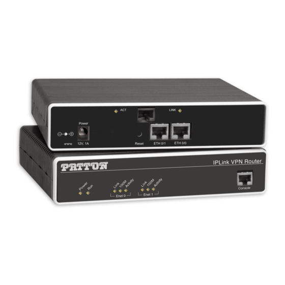
IPLink 3210 Series Getting Started Guide 1 • General information IPLink Model 3210 Series overview The IPLink Model 3210 Series G.SHDSL VPN Router (see figure 1) is a next generation business-class G.SHDSL router that addresses both the security and the traffic prioritization needs of enterprises while pro- viding complete broadband integration with existing DSLAM neteworks. -
Page 21: Iplink 3210 Series Detailed Description
Enhanced IP services include domain name service (DNS) resolver and relay, NAT/NAPT, dynamic DNS, and DHCP server. IPLink 3210 Series detailed description The IPLink 3210 Series G.SHDSL VPN Router provides secure managed VPN routed networking with 2- port Ethernet LAN connectivity and a G.SHDSL WAN interface (see figure IPLink 3210 G.SHDSL WAN port connector... -
Page 22: Ports Descriptions
IPLink 3210 Series Getting Started Guide 1 • General information • EUI stands for external 100–240V AC universal input power supply (see figure Ports descriptions The IPLink 3210 Series rear-panel ports are described in table Table 2. Rear panel ports Port Location Description... -
Page 23: Applications Overview
VPN connection through a frame-relay service network as delivered on serial lines. The IPLink 3210 Series can support a similar scenario with network service delivered via an Ether- net WAN interface. For remote sites where PPP service is available, the 3210 Series also supports PPP network access over all the standard WAN interface options mentioned above. -
Page 24: Corporate Multi-Function Virtual Private Network
45 to configure the VPN. Corporate multi-function virtual private network The IPLink 3210 Series can deliver both private corporate intranet service and public Internet access to multi- ple remote sites by leveraging IPLink’s multiple frame-relay PVC support (see figure... - Page 25 IPLink 3210 Series Getting Started Guide 1 • General information The corporate multi-function application carries two types of traffic between each remote office and corpo- rate’s central office: • Private corporate traffic (the intranet/extranet) • Internet traffic The service provider offers a Frame Relay network for access, so both the private corporate traffic and the Inter- net traffic is transported over a Frame Relay PVC with one DLCI.
-
Page 26: Hardware Installation
Chapter 2 Hardware installation Chapter contents Planning the installation ............................27 Installation checklist ............................28 Site log ................................29 Network information .............................29 Network Diagram .............................29 IP related information ............................29 Software tools ..............................29 Power source ..............................29 Location and mounting requirements ......................30 Installing the VPN router .............................30 Mounting the VPN router ..........................30... -
Page 27: Planning The Installation
IPLink 3210 Series Getting Started Guide 2 • Hardware installation Planning the installation Before you start the actual installation, we strongly recommend that you gather all the information you will need to install and setup the device. See table 3 for an example of what pre-installment checks you might need to carry out. -
Page 28: Installation Checklist
3) lists the tasks for installing an IPLink 3210 Series VPN Router. Make a copy of this checklist and mark the entries as you complete each task. For each IPLink 3210 Series VPN Router, include a copy of the completed checklist in your site log. -
Page 29: Site Log
Draw a network overview diagram that displays all neighboring IP nodes, connected elements and telephony components. IP related information Before you can set up the basic IP connectivity for your IPLink 3210 Series you should have the following information: •... -
Page 30: Location And Mounting Requirements
32) Installing the Ethernet cable The IPLink 3210 Series has automatic MDX (auto-cross-over) detection and configuration on the Ethernet ports. Any of the two ports can be connected to a host or hub/switch with a straight-through wired cable (see... -
Page 31: Installing The Dsl Cable
1 Rx+ 2 Rx- 3 Tx+ 6 Tx- Figure 7. Connecting an IPLink 3210 Series device to a hub Installing the DSL cable The IPLink 3210 comes with a G.SHDSL interface. Use a straight-through RJ-11 cable to connect the DSL port. -
Page 32: Connecting To External Power Source
IPLink 3210 Series Getting Started Guide 2 • Hardware installation Connecting to external power source The VPN Router comes with one of the following power supply options as best-suited to the expected installa- tion environment: • 120/140VAC internal power supply (designated by the model code extension UI) •... -
Page 33: Vpn Router Front Panel Leds And Console Port Locations
IPLink 3210 Series Getting Started Guide 2 • Hardware installation The UI and EUI power supplies automatically adjust to accept an input voltage from 100 to 240 VAC (50/60 Hz). Verify that the proper voltage is present before plugging the CAUTION power cord into the receptacle. -
Page 34: Getting Started With The Iplink
Chapter 3 Getting started with the IPLink Chapter contents Introduction ................................35 1. Configure IP address ............................36 Power connection and default configuration ....................36 Connect with the serial interface ........................36 Login ................................37 Changing the IP address ..........................37 2. Connect the IPLink VPN Router to the network....................38 3. -
Page 35: Introduction
IPLink 3210 Series Getting Started Guide 3 • Getting started with the IPLink Introduction This chapter leads you through the basic steps to set up a new IPLink VPN Router. Figure 10 show the main steps for setting up a new IPLink VPN Router. -
Page 36: Configure Ip Address
IPLink 3210 Series Getting Started Guide 3 • Getting started with the IPLink 1. Configure IP address Power connection and default configuration First the IPLink VPN Router must be connected to the mains power supply with the power cable. Wait until LED stops blinking and lights constantly. -
Page 37: Login
IPLink 3210 Series Getting Started Guide 3 • Getting started with the IPLink • 1 stop bit • No flow control Login Accessing your IPLink VPN Router via the local console port (or via a Telnet session) causes the login screen to display. -
Page 38: Connect The Iplink Vpn Router To The Network
IPLink 3210 Series Getting Started Guide 3 • Getting started with the IPLink 2. Connect the IPLink VPN Router to the network Depending whether you connect the IPLink VPN Router to a host directly or via a hub or switch either straight-through wired or cross-over cables must be used (see figure... - Page 39 IPLink 3210 Series Getting Started Guide 3 • Getting started with the IPLink After the IPLink VPN Router has been rebooted the new start up configuration will be activated. 172.16.1.99(if-ip)[eth0]#reload Running configuration has been changed. Do you want to copy the 'running-config' to the 'startup-config'?
-
Page 40: G.shdsl Basic Configuration
Chapter 4 G.SHDSL Basic Configuration Chapter contents Introduction ................................41 Line Setup ................................41 Configuring PPPoE ...............................41 Configuration Summary............................42 Setting up permanent virtual circuits (PVC)......................43 Using PVC channels in bridged Ethernet mode ....................43 Using PVC channels with PPPoE ........................43 Diagnostics ..............................44 Troubleshooting DSL Connections ........................44... -
Page 41: G.shdsl Basic Configuration
IPLink 3210 Series Getting Started Guide 4 • G.SHDSL Basic Configuration Introduction The IPLink 3210 model has an option for a built-in G.SHDSL modem. The modem appears in the configura- tion as "port dsl 0 0" mode. port dsl 0 0... -
Page 42: Configuration Summary
IPLink 3210 Series Getting Started Guide 4 • G.SHDSL Basic Configuration Next, you will need to create a WAN profile, create a WAN interface, and create a subscriber. Then, you can configure the DSL port (port dsl 0 0) for PPPoE. -
Page 43: Setting Up Permanent Virtual Circuits (Pvc)
IPLink 3210 Series Getting Started Guide 4 • G.SHDSL Basic Configuration Setting up permanent virtual circuits (PVC) The modems currently available are using ATM to multiplex traffic over the DSL framing connection. ATM allows you to have separate logical connections running in parallel. Those connections are called permanent virtual circuits (PVC). -
Page 44: Diagnostics
IPLink 3210 Series Getting Started Guide 4 • G.SHDSL Basic Configuration Diagnostics Table 10. Diagnostics commans Command Purpose Step 1 node> show dsl type Displays the type of modem installed. Step 2 node> show dsl line-state Displays information about the state of the DSL link. -
Page 45: Vpn Configuration
Chapter 5 VPN configuration Chapter contents Introduction ................................46 Authentication ..............................46 Encryption ..............................46 Transport and tunnel modes ...........................47 VPN configuration task list ...........................47 Creating an IPsec transformation profile ......................47 Creating an IPsec policy profile ........................48 Creating/modifying an outgoing ACL profile for IPsec ...................50 Configuration of an IP interface and the IP router for IPsec ................51... -
Page 46: Introduction
IPLink 3210 Series Getting Started Guide 5 • VPN configuration Introduction This chapter describes how to configure the VPN connections between two IPLink routers or between an IPLink and a third-party device. A virtual private network (VPN) is a private data network that uses the public telecommunications infrastruc- ture, maintaining privacy through the use of a tunneling protocol and security procedures. -
Page 47: Transport And Tunnel Modes
IPLink 3210 Series Getting Started Guide 5 • VPN configuration Transport and tunnel modes The mode determines the payload of the ESP packet and hence the application: • Transport mode: Encapsulates only the payload of the original IP packet, but not its header, so the IPsec peers must be at the endpoints of the communications link. -
Page 48: Creating An Ipsec Policy Profile
IPLink 3210 Series Getting Started Guide 5 • VPN configuration Creating an IPsec policy profile The IPsec policy profile supplies the keys for the encryption and/or the authenticators for the authentication, the security parameters indexes (SPIs), and IP address of the peer of the secured communication. Furthermore, the profile defines which IPsec transformation profile to apply and whether transport or tunnel mode shall be... - Page 49 IPLink 3210 Series Getting Started Guide 5 • VPN configuration Mode: Configure Step Command Purpose Creates the IPsec policy profile name node (cfg)#profile ipsec-policy-man- ual name Selects the IPsec transformation profile to be node (pf-ipstr)[name]#use profile ipsec-transform name applied node (pf-ipstr)[ name ]#session-key...
-
Page 50: Creating/Modifying An Outgoing Acl Profile For Ipsec
IPLink 3210 Series Getting Started Guide 5 • VPN configuration Example: Create an IPsec policy profile The following example defines a profile for AES-encryption at a key length of 128. 3210(cfg)#profile ipsec-policy-manual ToBurg 3210(pf-ipsma)[ToBurg]#use profile ipsec-transform AES_128 3210(pf-ipsma)[ToBurg]#session-key inbound esp-encryption 1234567890ABCDEF1234567890ABCDEF... -
Page 51: Configuration Of An Ip Interface And The Ip Router For Ipsec
IPLink 3210 Series Getting Started Guide 5 • VPN configuration Configuration of an IP interface and the IP router for IPsec The IP interface that provides connectivity to the IPsec peer, must now activate the outgoing ACL profile con- figured in the previous section. Furthermore, the IP router must have a route for the remote network that points to the respective IP interface. -
Page 52: Debugging Ipsec
IPLink 3210 Series Getting Started Guide 5 • VPN configuration Example: Display IPsec transformation profiles 3210(cfg)#show profile ipsec-transform IPSEC transform profiles: Name: AES_128 ESP Encryption: AES-CBC, Key length: 128 Example: Display IPsec policy profiles 3210(cfg)#show profile ipsec-policy-manual Manually keyed IPsec policy profiles: Name: ToBurg, Peer: 200.200.200.1, Mode: tunnel, transform-profile: AES_128... -
Page 53: Sample Configurations
IPLink 3210 Series Getting Started Guide 5 • VPN configuration MANUAL ToBurg Tunnel 200.200.200.1 1111 AES-CBC 128 3622/unlimited 19047/unlimited OUT MANUAL ToBurg Tunnel 200.200.200.1 2222 AES-CBC 128 2857/unlimited 19047/unlimited Sample configurations The following sample configurations establish IPsec connections between an IPLink and a Cisco router. To interconnect two IPLink routers instead, derive the configuration for the second IPLink by doing the following... -
Page 54: Cisco Router Configuration
IPLink 3210 Series Getting Started Guide 5 • VPN configuration use profile acl VPN_In in use profile acl VPN_Out out context ip router route 0.0.0.0 0.0.0.0 200.200.200.1 0 route 172.16.0.0 255.255.0.0 WAN 0 Cisco router configuration crypto ipsec transform-set DES esp-des... -
Page 55: Cisco Router Configuration
IPLink 3210 Series Getting Started Guide 5 • VPN configuration Cisco router configuration crypto ipsec transform-set AES_SHA1 ah-sha-hmac esp-aes 256 crypto map VPN_AES_SHA1 local-address FastEthernet0/1 crypto map VPN_AES_SHA1 10 ipsec-manual set peer 200.200.200.2 set session-key inbound esp 6666 cipher FEDCBA0987654321FEDCBA0987654321FEDCBA0987654321FEDCBA0987654321... - Page 56 IPLink 3210 Series Getting Started Guide 5 • VPN configuration match address 110 For the remainder of the configuration (see above), just change the name of the IPsec policy profile in the ACL profile VPN_Out. Sample configurations...
-
Page 57: Access Control List Configuration
Chapter 6 Access control list configuration Chapter contents Introduction ................................58 About access control lists ............................58 What access lists do ............................58 Why you should configure access lists ......................58 When to configure access lists .........................59 Features of access control lists .........................59 Access control list configuration task list........................60 Mapping out the goals of the access control list ....................60... -
Page 58: Introduction
IPLink 3210 Series Getting Started Guide 6 • Access control list configuration Introduction This chapter provides an overview of IP Access Control Lists and describes the tasks involved in configuring them through the IPLink router. This chapter includes the following sections: •... -
Page 59: When To Configure Access Lists
IPLink 3210 Series Getting Started Guide 6 • Access control list configuration For example, access lists can allow one host to access a part of your network, and prevent another host from accessing the same area. In figure 14 host A is allowed to access the Human Resources network and host B is prevented from accessing the Human Resources network. -
Page 60: Access Control List Configuration Task List
IPLink 3210 Series Getting Started Guide 6 • Access control list configuration • All access control lists have an implicit deny ip any any at the end. A packet that does not match the criteria of the first statement is subjected to the criteria of the second statement and so on until the end of the access control list is reached, at which point the packet is dropped. -
Page 61: Creating An Access Control List Profile And Enter Configuration Mode
IPLink 3210 Series Getting Started Guide 6 • Access control list configuration Before you begin to enter the commands that create and configure the IP access control list, be sure that you are clear about what you want to achieve with the list. Consider whether it is better to deny specific accesses and permit all others or to permit specific accesses and deny all others. - Page 62 IPLink 3210 Series Getting Started Guide 6 • Access control list configuration Mode: Profile access control list Step Command Purpose node (pf-acl)[ name ]#deny ip { src src-wildcard | any | host Creates an IP access of control list src } { dest dest-wildcard | any | host dest } [cos group ] entry that denies access defined...
-
Page 63: Adding An Icmp Filter Rule To The Current Access Control List Profile
IPLink 3210 Series Getting Started Guide 6 • Access control list configuration Adding an ICMP filter rule to the current access control list profile The command permit or deny are used to define an ICMP filter rule. Each ICMP filter rule represents an ICMP access of control list entry. - Page 64 IPLink 3210 Series Getting Started Guide 6 • Access control list configuration Where the syntax is as following: Keyword Meaning The source address to be included in the rule. An IP address in dotted-decimal-format, e.g. 64.231.1.10. A wildcard for the source address. Expressed in dotted-decimal format this value specifies src-wildcard which bits are significant for matching.
-
Page 65: Adding A Tcp, Udp Or Sctp Filter Rule To The Current Access Control List Profile
IPLink 3210 Series Getting Started Guide 6 • Access control list configuration The same effect can also be obtained by using the simpler message name option. See the following example. 3210(cfg)#profile acl WanRx 3210(pf-acl)[WanRX]#deny icmp any any msg echo 3210(pf-acl)[WanRX]#exit 3210(cfg)# Adding a TCP, UDP or SCTP filter rule to the current access control list profile... - Page 66 IPLink 3210 Series Getting Started Guide 6 • Access control list configuration Where the syntax is: Keyword Meaning The source address to be included in the rule. An IP address in dotted-decimal-format, e.g. 64.231.1.10. A wildcard for the source address. Expressed in dotted-decimal format this value specifies src-wildcard which bits are significant for matching.
-
Page 67: Binding And Unbinding An Access Control List Profile To An Ip Interface
IPLink 3210 Series Getting Started Guide 6 • Access control list configuration Binding and unbinding an access control list profile to an IP interface The command use is used to bind an access control list profile to an IP interface. This procedure describes how to bind an access control list profile to incoming packets on an IP interface... -
Page 68: Displaying An Access Control List Profile
IPLink 3210 Series Getting Started Guide 6 • Access control list configuration Unbind an access control list profile from an interface. 3210(cfg)#context ip router 3210(cfg-ip)[router]#interface wan 3210(cfg-if)[wan]#no use profile acl in Note When unbinding an access control list profile the name argument is not required, since only one incoming and outgoing access control list can be active at the same time on a certain IP interface. - Page 69 IPLink 3210 Series Getting Started Guide 6 • Access control list configuration Mode: Interface Step Command Purpose Selects the IP router context node (cfg)#context ip router node (ctx-ip)[router]#interface if-name Selects IP interface if-name for which access control list profile shall be debugged...
-
Page 70: Examples
IPLink 3210 Series Getting Started Guide 6 • Access control list configuration Examples Denying a specific subnet Figure 15 shows an example in which a server attached to network 172.16.1.0 shall not be accessible from outside networks connected to IP interface lan of the IPLink device. To prevent access, an incoming filter rule named Jamming is defined, which blocks any IP traffic from network 172.16.2.0 and has to be bound to IP interface lan. -
Page 71: Link Scheduler Configuration
Chapter 7 Link scheduler configuration Chapter contents Introduction ................................72 Configuring access control lists..........................72 Configuring quality of service (QoS) ........................73 Applying scheduling at the bottleneck ......................73 Using traffic classes ............................73 Introduction to Scheduling ..........................74 Priority ..............................74 Weighted fair queuing (WFQ) ........................74 Shaping ..............................75 Burst tolerant shaping or wfq... -
Page 72: Introduction
IPLink 3210 Series Getting Started Guide 7 • Link scheduler configuration Introduction This chapter describes how to use and configure the IPLink Quality of Service (QoS) features. Refer to 6, “Access control list configuration” on page 57 for more information on the use of access control lists. -
Page 73: Configuring Quality Of Service (Qos)
IPLink 3210 Series Getting Started Guide 7 • Link scheduler configuration NAPT Profile Service Policy Profile router Context use command use command Interfaces Profile bind command bind command Circuit Ports Figure 16. IP context and related elements Configuring quality of service (QoS) In the IPLink 3210, the link scheduler enables the definition of QoS profiles for network traffic on a certain... -
Page 74: Introduction To Scheduling
IPLink 3210 Series Getting Started Guide 7 • Link scheduler configuration can be used to mark a specific packet type for the other network nodes. By default the traffic-class tag is empty. Refer to figure 17 on page 74 when using the ACL to classify traffic. It illustrates the sequence of processing stages every routed packet passes. -
Page 75: Shaping
IPLink 3210 Series Getting Started Guide 7 • Link scheduler configuration Each traffic-class is in fact assigned a relative weight, which is used to share the bandwidth among the currently active classes. Patton recommends that you specify the weight as percent which is best readable. -
Page 76: Quick References
IPLink 3210 Series Getting Started Guide 7 • Link scheduler configuration Mode priority critical_q min. 30% min. 40% Level_1 min. 30% Mail Low_Priority Default Mode Shaper Define 2nd level Define 1st level Use arbiter on arbiter arbiter an interface Figure 18. Example of Hierarchical Scheduling Quick references The following sections provide a minimal “standard”... -
Page 77: Command Cross Reference
IPLink 3210 Series Getting Started Guide 7 • Link scheduler configuration • “modem-512” is the title of the profile which is referred to when installing the scheduler • “rate-limit 512” allows no more than 512 kbit/sec to pass which avoids queueing in the modem. -
Page 78: Defining The Access Control List Profile
IPLink 3210 Series Getting Started Guide 7 • Link scheduler configuration • Displaying link scheduling profile information (see page 88) • Enable statistics gathering (see page 88) Profile Packet Classification Predefined Classes Different Types (Classes) of Traffic The service-policy profile... -
Page 79: Creating An Access Control List
IPLink 3210 Series Getting Started Guide 7 • Link scheduler configuration Some types of packets you do not have to tag with ACL. Voice and data packets from of for the IPLink itself are automatically tagged with predefined traffic-class names: Predefined internal classes for data are: •... -
Page 80: Creating A Service Policy Profile
IPLink 3210 Series Getting Started Guide 7 • Link scheduler configuration Mode: Configure Step Command Purpose node (cfg)#profile acl name Creates a new access control list profile named name node (pf-acl)[ name ]#permit ip host ip-address any traffic-class Creates an IP access con-... - Page 81 IPLink 3210 Series Getting Started Guide 7 • Link scheduler configuration profile service-policy <profile-name> link rate, arbitration common settings common parameters source traffic-class <x> bandwidth, packet mark settings for class x queue-size, etc. source traffic-class <y> settings for class y...
-
Page 82: Specifying The Handling Of Traffic-Classes
IPLink 3210 Series Getting Started Guide 7 • Link scheduler configuration At a some point the source traffic-class default must be listed. This class must be present, because it defines how packets, which do not belong to any of the traffic-classes listed in the profile are to be handled. When all listed “traffic-classes”... -
Page 83: Defining The Bit-Rate
IPLink 3210 Series Getting Started Guide 7 • Link scheduler configuration Mode: Source Command Purpose node (src)[ name ]#share percentage Defines fair queuing weight (relative to other sources) to percent- age for the selected class or policy name Defining the bit-rate... -
Page 84: Specifying The Precedence Field
IPLink 3210 Series Getting Started Guide 7 • Link scheduler configuration The type-of-service (TOS) byte in an IP header specifies precedence (priority) and type of service (RFC791, RFC1349). The precedence field is defined by the first three bits and supports eight levels of priority. The next four bits—which are set by the... -
Page 85: Specifying Layer 2 Marking
IPLink 3210 Series Getting Started Guide 7 • Link scheduler configuration “traffic-class” number called. With IPLink you can inspect the DSCP value in the ACL rules and modify the DSCP value with the link scheduler command. set ip dscp Note When configuring service differentiation on the IPLink router, ensure... -
Page 86: Defining Random Early Detection
IPLink 3210 Series Getting Started Guide 7 • Link scheduler configuration Defining random early detection The command is used to request random early detection (RED). When a queue carries lots of random-detect TCP transfers that last longer than simple web requests, there is a risk that TCP flow-control might be ineffi- cient. -
Page 87: Devoting The Service Policy Profile To An Interface
IPLink 3210 Series Getting Started Guide 7 • Link scheduler configuration Devoting the service policy profile to an interface Any service policy profile needs to be bound to a certain IP interface to get activated. According the terminol- ogy of IPLink a service policy profile is used on a certain IP interface, as shown in figure... -
Page 88: Displaying Link Arbitration Status
IPLink 3210 Series Getting Started Guide 7 • Link scheduler configuration 3210>enable 3210#configure 3210(cfg)#context ip router 3210(ctx-ip)[router]#interface wan 3210(if-ip)[wan]#use profile service-policy Voice_Prio out Displaying link arbitration status command displays link arbitration status. This command supports the optional show service-policy argument interface that select a certain IP interface. - Page 89 IPLink 3210 Series Getting Started Guide 7 • Link scheduler configuration The command has optional values (in the range of 1 to 4) that define the level of detail (see table 14). Table 14. Values defining detail of the queuing statistics...
-
Page 90: Leds Status And Monitoring
Chapter 8 LEDs status and monitoring Chapter contents Status LEDs................................91... -
Page 91: Status Leds
Console Enet 0 Enet 1 Console port L i n o le Figure 23. Examples of IPLink 3210 Series front panels Table 15. IPLink LED Indications Description Note If an error occurs, all LEDs will flash once per second. Power When lit, indicates power is applied. -
Page 92: Contacting Patton For Assistance
Chapter 9 Contacting Patton for assistance Chapter contents Introduction ................................93 Contact information..............................93 Patton Support Headquarters in the USA .......................93 Alternate Patton support for Europe, Middle Ease, and Africa (EMEA) ............93 Warranty Service and Returned Merchandise Authorizations (RMAs)..............93 Warranty coverage ............................93 Out-of-warranty service ..........................94 Returns for credit... -
Page 93: Introduction
IPLink 3210 Series Getting Started Guide 9 • Contacting Patton for assistance Introduction This chapter contains the following information: • “Contact information”—describes how to contact Patton technical support for assistance. • “Warranty Service and Returned Merchandise Authorizations (RMAs)”—contains information about the RAS warranty and obtaining a return merchandise authorization (RMA). -
Page 94: Out-Of-Warranty Service
IPLink 3210 Series Getting Started Guide 9 • Contacting Patton for assistance Out-of-warranty service Patton services what we sell, no matter how you acquired it, including malfunctioning products that are no longer under warranty. Our products have a flat fee for repairs. Units damaged by lightning or other catastro- phes may require replacement. - Page 95 Appendix A Compliance information Chapter contents Compliance ................................96 ................................96 Safety ................................96 PSTN Regulatory ............................96 Radio and TV Interference (FCC Part 15) ......................96 CE Declaration of Conformity ..........................96 Authorized European Representative ........................97 FCC Part 68 (ACTA) Statement ...........................97 Industry Canada Notice ............................97...
-
Page 96: A Compliance Information
IPLink 3210 Series Getting Started Guide A • Compliance information Compliance • FCC Part 15, Class A • EN55022, Class A • EN55024 Safety • UL 60950-1/CSA C22.2 N0.60950-1 • IEC/EN60950-1 • AS/NZS 60950-1 PSTN Regulatory • ACTA Part 68 •... -
Page 97: Authorized European Representative
IPLink 3210 Series Getting Started Guide A • Compliance information Authorized European Representative D R M Green European Compliance Services Limited. Oakdene House, Oak Road Watchfield, Swindon, Wilts SN6 8TD, UK FCC Part 68 (ACTA) Statement This equipment complies with Part 68 of FCC rules and the requirements adopted by ACTA. On the bottom side of this equipment is a label that contains—among other information—a product identifier in the format... - Page 98 Appendix B Specifications Chapter contents Ethernet interfaces ..............................99 PPP support ................................99 IP services ................................99 Management .................................99 Operating environment ............................99 Operating temperature ............................99 Operating humidity ............................99 System .................................100 Dimensions .................................100 G.SHDSL Daughter Card ...........................101 Power supply ...............................102 Internal AC version ............................102 12VDC version with External AC Power Adapter ..................102 5VDC Version with External Power Adapter...
-
Page 99: B Specifications
IPLink 3210 Series Getting Started Guide B • Specifications Ethernet interfaces 10/100Base-TX Ethernet WAN port 10/100Base-TX Ethernet LAN port All ports full duplex, autosensing, auto-MDIX 10/100 Full Duplex/Autosensing Ethernet RJ-45 PPP support Frame-Relay (8 PVCs) RFC1490, FRF.12 fragmentation LMI, Q.933D, ANSI 617D, Gang of Four... -
Page 100: System
IPLink 3210 Series Getting Started Guide B • Specifications System CPU Motorola MPC875 operating at 66 MHz Memory: • 32 Mbytes SDRAM • 8 Mbytes Flash Dimensions 7.3W x 1.6H x 6.1D in. (18.5H x 4.1W x 15.5D cm) System... -
Page 101: G.shdsl Daughter Card
IPLink 3210 Series Getting Started Guide B • Specifications G.SHDSL Daughter Card Note For information on configuring the G.SHDSL daughter card, see Chapter 4, “G.SHDSL Basic Configuration” on page 40. Table 16. G.SHDSL Daughter Card Specifications Factor Specs • ITU-T G.991.2 (and Amendment 2) •... -
Page 102: Power Supply
IPLink 3210 Series Getting Started Guide B • Specifications Power supply Internal AC version Internal power supply 100–240 VAC, 50/60 Hz, 200 mA 12VDC version with External AC Power Adapter Uses external AC Adaptor which provides 12VDC via barrel type connector AC Adapter Input: 90-264VAC, 47-63Hz AC Adapter Output: 12 VDC, 1.25A max... -
Page 103: Cabling
Appendix C Cabling Chapter contents Introduction ................................104 Serial console ..............................104 Ethernet 10Base-T and 100Base-T ........................105... -
Page 104: Introduction
IPLink 3210 Series Getting Started Guide C • Cabling Introduction This section provides information on the cables used to connect the IPLink to the existing network infrastruc- ture and to third party products. The interconnecting cables must be acceptable for external use and must be rated for the proper application with respect to volt- age, current, anticipated temperature, flammability, and... -
Page 105: Ethernet 10Base-T And 100Base-T
IPLink 3210 Series Getting Started Guide C • Cabling Ethernet 10Base-T and 100Base-T Ethernet devices (10Base-T/100Base-T) are connected to the IPLink over a cable with RJ-45 plugs. Use a cross-over cable to a host, or a straight cable to a hub. See figure 25... -
Page 106: Ethernet Straight-Through
IPLink 3210 Series Getting Started Guide C • Cabling Straight-through cable RJ-45, male RJ-45, male 1 Rx+ 2 Rx- 3 Tx+ 6 Tx- Figure 26. Ethernet straight-through Ethernet 10Base-T and 100Base-T... -
Page 107: Console Port
Appendix D Port pin-outs Chapter contents Introduction ................................108 Console port, RJ-45, EIA-561 (RS-232)......................108 Ethernet 10Base-T and 100Base-T port ......................109 ..................................109... -
Page 108: D Port Pin-Outs
IPLink 3210 Series Getting Started Guide D • Port pin-outs Introduction This section provides pin-out information for the ports of the IPLink router. Console port, RJ-45, EIA-561 (RS-232) The RS-232 serial console port of the IPLink is configured to operate as a DCE. View the image in figure 27... -
Page 109: Ethernet 10Base-T And 100Base-T Port
IPLink 3210 Series Getting Started Guide D • Port pin-outs Ethernet 10Base-T and 100Base-T port Table 18. RJ-45 socket Signal Direction from IPLink from IPLink to IPLink to IPLink The Ethernet ports are auto-detect MDI-X. Note Pins not listed are not used. -
Page 110: Iplink 3210 Series Factory Configuration
Appendix E IPLink 3210 Series factory configuration Chapter contents Introduction ................................111... -
Page 111: Introduction
IPLink 3210 Series Getting Started Guide E • IPLink 3210 Series factory configuration Introduction The factory configuration settings for the IPLink 3210 Series devices are as follows: #----------------------------------------------------------------# # 3210 Series # R3.xx BUILDxxxxx # 2005-01-18T00:00:00 # Factory configuration file... -
Page 112: Installation Checklist
Appendix F Installation checklist Chapter contents Introduction ................................113... -
Page 113: Introduction
This appendix lists the tasks for installing an IPLink 3210 Series G.SHDSL VPN Router (see table 20). Make a copy of this checklist and mark the entries as you complete each task. For each IPLink 3210 Series Router, include a copy of the completed checklist in your site log. Table 20. Installation checklist Task Verified by...
Need help?
Do you have a question about the IPLink 3210 Series and is the answer not in the manual?
Questions and answers