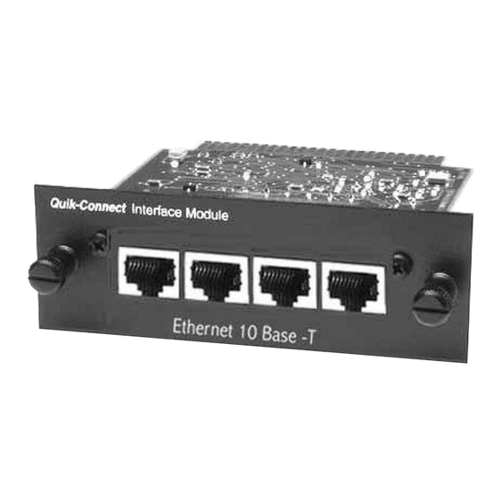
Summary of Contents for Patton electronics IM1/I4
- Page 1 Ethernet Bridge with Integral 4-Port Hub QuikConnect™ Module Part# 07MIM1/I4-C SALES OFFICE Doc# 090141UC (301) 975-1000 Revised 07/19/00 TECHNICAL SUPPORT C E R T I F I E D (301) 975-1007 An ISO-9001 http://www.patton.com Certified Company...
-
Page 2: Radio And Tv Interference
The Model IM1/I4 has been tested and complies with the limits for a Class A computing device in accordance with the specifi-... -
Page 3: Typical Application
The Model IM1/I4 QuickConnect™ is designed to plug directly into the rear of a Patton Electronics baseband modem (e.g. Model 1092A or 1095). The Model IM1/I4 is designed to be used as one of a pair of units. Figure 1 (below) illustrates a typical Model IM1/I4 instal- lation. - Page 4 Ethernet network. The serial interface on the Cisco will have an IP address on the same Ethernet subnet as the bridge. Patton Router IM1/I4 Bridge Ethernet LAN PEC Device w/ Serial I/F Figure 2. Cisco router with serial interface, configured as PPP Half Bridge.
- Page 5 The instructions below describe how to remove the existing QuickConnect™ Module and how to install the new IM1/I4 module. If your base unit does not have an existing QuickConnect™ already installed, please skip to sec- tion 4.1.2.
-
Page 6: Connecting To The 10Base-T Ethernet Port
The Model IM1/I4 10Base-T hub interfaces are configured as DCE (Data Circuit Terminating Equipment). Therefore, it “expects” to con- nect to a 10Base-T workstation using a straight-through RJ-45 cable. Use the diagram below to construct a cable to connect the IM1/I4 to a workstation. IM1/I4 RJ-45 Pin No. - Page 7 LED status monitors. 5.1 OPERATING INSTRUCTIONS In order to operate, the Model IM1/I4 must be installed in the base unit. It also requires a 10Base-T connection. After power is applied, the IM1/I4 automatically starts performing the bridging function without further user intervention.
-
Page 8: Led Status Monitors
5.3 LED STATUS MONITORS The Model IM1/I4 features two LEDs that monitor general operat- ing status and the 10Base-T twisted pair link integrity. Figure 6 (below) shows the LEDs located directly beneath the RJ-45 jack. Following Figure 6 is a description of each LEDs function. - Page 9 10BASE-T Interface Pin Description (RJ-45 Female Connector) (Hub Configuration) Pin # Signal RD + (data input to IM1/I4) RD - (data input to IM1/I4) TD + (data output from IM1/I4) no connection no connection TD - (data output from IM1/I4)


Need help?
Do you have a question about the IM1/I4 and is the answer not in the manual?
Questions and answers