Table of Contents

Summary of Contents for Patton electronics IM 1/I
- Page 1 USER MANUAL MODEL IM 1/I Ethernet Bridge Module Part# 07MIM1/I-E Doc# 090101U, Rev. F C E R T I F I E D Revised 1/22/08 An ISO-9001 Certified Company SALES OFFICE (301) 975-1000 TECHNICAL SUPPORT (301) 975-1007 http://www.patton.com...
-
Page 2: Radio And Tv Interference
1.1 RADIO AND TV INTERFERENCE The Model IM1/I generates and uses radio frequency energy, and if not installed and used properly—that is, in strict accordance with the manufacturer’s instructions—may cause interference to radio and television reception. - Page 3 1.3 SERVICE All warranty and nonwarranty repairs must be returned freight prepaid and insured to Patton Electronics. All returns must have a Return Materials Authorization number on the outside of the shipping container. This number may be obtained from Patton Electronics Technical Service at: (301) 975-1007, http://www.patton.com;...
-
Page 4: General Information
“plug and play” manner to forward LAN broadcasts, multicasts and frames destined for the peered Ethernet LAN at the remote end (the Patton base unit at the remote end must also be equipped with an IM1/I module). Using the Patton IM1/I, peered Ethernet LANs can be linked... -
Page 5: Typical Application
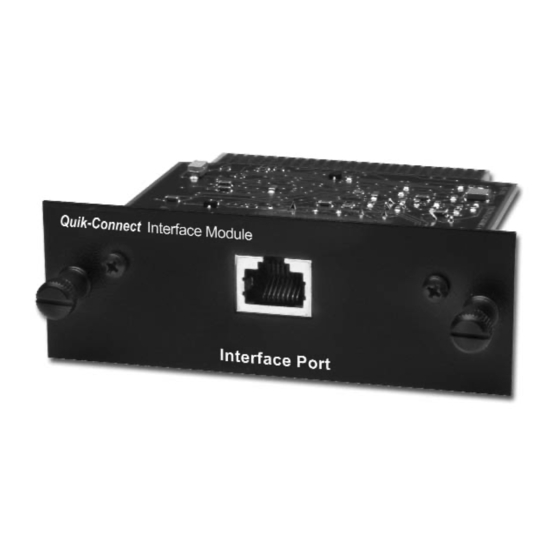
The Model IM1/I QuickConnect™ is designed to plug directly into the rear of a Patton Electronics baseband modem (i.e. Model 1090 or 1092). The Model IM1/I is designed to be used as one of a pair of units. Figure 1 (below) illustrates a typical Model IM1/I installation. -
Page 6: Ppp Operational Background
3.0 PPP OPERATIONAL BACKGROUND PPP is a protocol used for multi-plexed transport over a point- to-point link. PPP operates on all full duplex media, and is a symmetric peer-to-peer protocol, which can be broken into three main components: 1. A standard method to encapsulate datagrams over serial links;... - Page 7 Patton IM1/I Bridge Ethernet LAN Customer Site Figure 2. Cisco router with serial interface, configured as PPP Half Bridge. For example, the customer site is assigned the addresses 192.168.1.0/24 through 192.168.1.1/24. The address 192.168.1.1/24 is also the default gateway for the remote network.
- Page 8 4.0 CONFIGURATION The Model IM1/I module plugs into Patton’s fiber and copper baseband modems to provide Ethernet LAN extension. The IM1/I has no switches or jumpers and does not need to be configured. However, factors such as ty type of medium, throughput across the link and clocking mode must be determined by the settings of the baseband modems.
-
Page 9: Installation
The instructions below describe how to remove the existing QuickConnect™ Module and how to install the new IM1/I module. If your base unit does not have an existing QuickConnect™ already installed, please skip to section 3.2.2. - Page 10 5.1.2 Installing the New QuickConnect™ Module 1) Make sure the power switch on the base unit is off. Leave the power cord plugged into a grounded outlet to keep the unit grounded. 2) Hold the module with the faceplate toward you and align the module with the guide slots in the rear panel of the base unit.
-
Page 11: Connecting To The 10Base-T Ethernet Port
5.2.2 Connecting the 10Base-T Ethernet Port to a PC (DTE) The Model IM1/I 10Base-T interface is configured as DTE (Data Terminal Equipment). If you wish to connect the IM1/I to another DTE device such as a 10Base-T network interface card in a PC, you must construct a 10Base-T crossover cable as shown in the diagram below. - Page 12 Please refer to the base unit manual for connection details. Notice! Any terminal cable connected to the Model IM1/I must be shielded cable, and the outer shield must be 360 degree bonded–at both ends–to a metal or metalized backshell.
-
Page 13: Operation
LED status monitors. 6.1 OPERATING INSTRUCTIONS In order to operate, the Model IM1/I must be installed in the base unit. It also requires a 10Base-T connection. After power is applied, the IM1/I automatically starts performing the bridging function without further user intervention. -
Page 14: Led Status Monitors
6.3 LED STATUS MONITORS The Model IM1/I features two LEDs that monitor general operating status and the 10Base-T twisted pair link integrity. Figure 6 (below) shows the LEDs located directly beneath the RJ-45 jack. Following Figure 6 is a description of each LEDs function. - Page 15 PATTON MODEL IM1/I SPECIFICATIONS LAN Connection: Protocol: MAC Address Table Size: MAC Address Aging: On-board Memory: Frame Latency: Interface: LED Indicators: Power Supply: Temperature Range: Dimensions: Weight: APPENDIX A RJ-45, 10Base-T, 802.3 Ethernet PPP (RFC 1661) with Bridging Control Protocol (RFC 1638)
- Page 16 IM1/I INTERFACE PIN ASSIGNMENT 10BASE-T Interface Pin Description (RJ-45 Female Connector) (DTE Configuration) Pin # Signal TD + (data output from IM1/I) TD - (data output from IM1/I) RD +(data input to IM1/I) no connection no connection RD - (data input to IM1/I)
- Page 17 Dear Valued Customer, Thank you for purchasing Patton Electronics products! We do appreciate your business. I trust that you find this user manual helpful. We manufacture one of the widest selections of data communications products in the world including CSU/DSU's, network termination units, powered and self-powered short range modems, fiber optic modems, interface converters, baluns, electronic data switches, data-line surge protectors, multiplexers, transceivers, hubs, print servers and much more.


Need help?
Do you have a question about the IM 1/I and is the answer not in the manual?
Questions and answers