Table of Contents
Advertisement
Quick Links
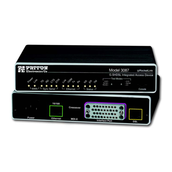
ipRocketLink™ Model 3087
Serial G.SHDSL Bridge/Router
Quick Start Guide
Important
intended nor approved for use in an industrial or residential environment.
Part Number: 07M3087-QS, Rev. C
Revised: February 15, 2012
—This is a Class A device and is intended for use in a light industrial environment. It is not
Sales Office: +1 (301) 975-1000
Technical Support: +1 (301) 975-1007
E-mail: support@patton.com
WWW: www.patton.com
Advertisement
Table of Contents

Summary of Contents for Patton electronics Serial G.SHDSL Bridge/Router 3087
-
Page 1: Quick Start Guide
ipRocketLink™ Model 3087 Serial G.SHDSL Bridge/Router Quick Start Guide Important —This is a Class A device and is intended for use in a light industrial environment. It is not intended nor approved for use in an industrial or residential environment. Part Number: 07M3087-QS, Rev. - Page 2 • This device contains no user serviceable parts. The equipment shall be returned to Patton Electronics for repairs, or repaired by qualified service personnel. WARNING • Mains Voltage: Do not open the case the when the power cord is attached. Line voltages are present within the power supply when the power cords are connected.
- Page 3 Insert the male plug of the AC power cord into an AC power outlet (100–240 VAC) 1.3 Power-up indication The Power LED blinks as the ipRocketLink is powering up. When the Power LED stops blinking and remains lit, the ipRocketLink is ready for you to configure. 2.0 Configure the IP address The ipRocketLink is shipped with a factory-configured IP address assigned to the Ethernet LAN port (green out- line).
- Page 4 IP Interfaces: ID | Name | IP Address ---|------|----------------|----------|-------------- | ip1 | 192.168.200.10 | disabled | <bridge> ---------------------------------------------- Modify the IP address for the LAN port according to your network requirements. ip set interface ip1 ipaddress 10.10.10.5 255.255.255.0 fi The above IP address ( Note subnet as your PC.
-
Page 5: Connect The Serial Port
4.0 Log onto the web management interface You will now access the web management graphical user interface (GUI) to configure the ipRocketLink using a standard web browser (such as Internet Explorer or Netscape browser). At your PC, open a web browser and enter the IP address you assigned to the ipRocketLink’s Ethernet LAN port in step 2 of section Log in to the web management home page using the username superuser and the password superuser. -
Page 6: Additional Information
Connect the serial cable to the ipRocketLink serial port as follows: Attach the male connector of the serial cable to the female serial connector on the IAD. Attach the other end of the cable to the serial connector on local serial NTU. The 3087’s V.35 interface is wired as a DCE. -
Page 7: Compliance Information
B.0 Key factory default parameters Key factory default parameters: C.0 Compliance Information C.1 Compliance EMC: FCC Part 15, Class A • EN55022, Class A • EN55024 • Safety: UL60950-1/CSA C22.2 No. 60950-1 • IEC/EN 60950-1 • AS/NZS 60950-1 • PSTN Regulatory: FCC Part 68 •... - Page 8 C.2 Radio and TV Interference (FCC Part 15) This equipment generates and uses radio frequency energy, and if not installed and used properly—that is, in strict accordance with the manufacturer's instructions—may cause interference to radio and television recep- tion. This equipment has been tested and found to comply with the limits for a Class A computing device in accor- dance with the specifications in Subpart B of Part 15 of FCC rules, which are designed to provide reasonable protection from such interference in a commercial installation.
- Page 9 pany will notify the customer as soon as possible. Also, you will be advised of your right to file a complaint with the FCC if you believe it is necessary. The telephone company may make changes in its facilities, equipment, operations or procedures that could affect the operation of the equipment.
-
Page 10: Copyright Statement
Copyright statement Copyright © 2012, Patton Electronics Company. All rights reserved. The information in this document is subject to change without notice. Patton Electronics assumes no liability for errors that may appear in this document. Trademarks statement The term ipRocketLink is a trademark of Patton Electronics Company. All other trademarks presented in this doc- ument are the property of their respective owners. - Page 11 NOTES ____________________________________________________________________ ____________________________________________________________________ ____________________________________________________________________ ____________________________________________________________________ ____________________________________________________________________ ____________________________________________________________________ ____________________________________________________________________ ____________________________________________________________________ ____________________________________________________________________ ____________________________________________________________________ ____________________________________________________________________ ____________________________________________________________________ ____________________________________________________________________ ____________________________________________________________________ ____________________________________________________________________ ____________________________________________________________________ Model 3087 Quick Start Guide...
- Page 12 NOTES ____________________________________________________________________ ____________________________________________________________________ ____________________________________________________________________ ____________________________________________________________________ ____________________________________________________________________ ____________________________________________________________________ ____________________________________________________________________ ____________________________________________________________________ ____________________________________________________________________ ____________________________________________________________________ ____________________________________________________________________ ____________________________________________________________________ ____________________________________________________________________ ____________________________________________________________________ ____________________________________________________________________ ____________________________________________________________________ Model 3087 Quick Start Guide...


Need help?
Do you have a question about the Serial G.SHDSL Bridge/Router 3087 and is the answer not in the manual?
Questions and answers