Table of Contents
Advertisement
Quick Links
IPLink 2800 Series
Managed VPN Router
Getting Started Guide
Important
This is a Class A device and is intended for use in a light industrial environment. It is not intended nor approved for use in an industrial
or residential environment.
Sales Office:
+1 (301) 975-1000
Technical Support:
+1 (301) 975-1007
E-mail: support@patton.com
WWW: www.patton.com
Document Number: 13220U1-001 Rev. E
Part Number: 07M2800-GS
Revised: April 27, 2007
Advertisement
Table of Contents

Related Manuals for Patton electronics IPLink 2821


Summary of Contents for Patton electronics IPLink 2821
- Page 1 IPLink 2800 Series Managed VPN Router Getting Started Guide Important This is a Class A device and is intended for use in a light industrial environment. It is not intended nor approved for use in an industrial or residential environment. Sales Office: +1 (301) 975-1000 Technical Support:...
- Page 2 E-Mail: support@patton.com Trademark Statement The term IPLink is a trademark of Patton Electronics Company. All other trademarks presented in this document are the property of their respective owners. Copyright © 2005 - 2007, Patton Electronics Company. All rights reserved. The information in this document is subject to change without notice. Patton Elec- tronics assumes no liability for errors that may appear in this document.
-
Page 3: Summary Table Of Contents
Summary Table of Contents General information............................19 Hardware installation............................ 28 Getting started with the IPLink Managed VPN Router ................40 Serial port configuration ..........................46 T1/E1 port configuration ..........................60 VPN configuration ............................69 Access control list configuration........................81 Link scheduler configuration ........................ - Page 4 IPLink 2800 Series Getting Started Guide Summary Table of Contents...
-
Page 5: Table Of Contents
Table of Contents Summary Table of Contents ........................... 3 Table of Contents ............................5 List of Figures ............................... 11 List of Tables ..............................12 About this guide ............................13 Audience................................13 Structure................................13 Precautions ................................14 Safety when working with electricity .......................15 General observations ............................16... - Page 6 IPLink 2800 Series Getting Started Guide Table of Contents Installing the T1/E1 twisted pair cables ....................36 Installing the E1 dual coaxial cables ....................37 Connecting to external power source ......................38 Getting started with the IPLink Managed VPN Router ................40 Introduction ................................41 1.
- Page 7 IPLink 2800 Series Getting Started Guide Table of Contents Configuring Channel-Group Timeslots ......................65 Configuring Channel-Group Encapsulation ....................65 Entering HDLC Configuration Mode ......................65 Configuring HDLC CRC-Type ........................66 Configuring HDLC Encapsulation .........................66 T1/E1 Configuration Examples ........................66 Example 1: Frame Relay without a channel-group ..................67 Example 2: Framerelay with a channel-group ....................68...
- Page 8 IPLink 2800 Series Getting Started Guide Table of Contents Adding an ICMP filter rule to the current access control list profile ..............87 Adding a TCP, UDP or SCTP filter rule to the current access control list profile ...........89 Binding and unbinding an access control list profile to an IP interface ............91 Displaying an access control list profile ......................92...
- Page 9 IPLink 2800 Series Getting Started Guide Table of Contents Status LEDs.................................115 Contacting Patton for assistance ......................... 116 Introduction ................................117 Contact information............................117 Patton Support Headquarters in the USA .....................117 Alternate Patton support for Europe, Middle Ease, and Africa (EMEA) ............117 Warranty Service and Returned Merchandise Authorizations (RMAs)..............117 Warranty coverage ............................117...
- Page 10 IPLink 2800 Series Getting Started Guide Table of Contents Ethernet 10Base-T and 100Base-T ........................128 Port pin-outs .............................. 130 Introduction ................................131 Console port, RJ-45, EIA-561 (RS-232)......................131 Ethernet 10Base-T and 100Base-T port.......................132 Sync serial port ..............................132 V.35 serial port .............................132 X.21 serial port .............................133 IPLink 2800 Series factory configuration ....................
-
Page 11: List Of Figures
List of Figures IPLink Managed VPN Router (2805 shown) ..........20 IPLink 2800 Series X.21, and V.35 connectors . -
Page 12: List Of Tables
List of Tables General conventions ..............17 Rear panel ports . -
Page 13: About This Guide
About this guide This guide describes IPLink VPN router hardware, installation, and configuration. Audience This guide is intended for the following users: • Operators • Installers • Maintenance technicians Structure This guide contains the following chapters and appendices: • Chapter 1 on page 19 provides information about router features, capabilities, operation, and applications •... -
Page 14: Precautions
IPLink 2800 Series Getting Started Guide About this guide Precautions Notes, cautions, and warnings, which have the following meanings, are used throughout this guide to help you become aware of potential problems. Warnings are intended to prevent safety hazards that could result in per- sonal injury. -
Page 15: Safety When Working With Electricity
About this guide Safety when working with electricity The IPLink contains no user serviceable parts. The equipment shall be returned to Patton Electronics for repairs, or repaired by qualified service personnel. Opening the IPLink case will void the warranty. WARNING Mains Voltage: Do not open the case the when the power cord is attached. -
Page 16: General Observations
IPLink 2800 Series Getting Started Guide About this guide The power supply automatically adjusts to accept an input volt- age from 100 to 240 VAC (50/60 Hz). Verify that the proper voltage is present before plugging the CAUTION power cord into the receptacle. Failure to do so could result in equipment damage. -
Page 17: Typographical Conventions Used In This Document
IPLink 2800 Series Getting Started Guide About this guide Typographical conventions used in this document This section describes the typographical conventions and terms used in this guide. General conventions The procedures described in this manual use the following text conventions: Table 1. - Page 18 IPLink 2800 Series Getting Started Guide About this guide...
-
Page 19: General Information
Chapter 1 General information Chapter contents IPLink Model 2800 Series overview........................20 IPLink 2800 Series detailed description ......................21 IPLink 2800 Series model codes ......................21 Serial WAN models ........................... 21 Ethernet WAN models ........................22 Model code extensions ..........................23 Ports descriptions .............................24 Applications overview............................25 Branch-Office virtual private network over Frame Relay service... -
Page 20: Iplink Model 2800 Series Overview
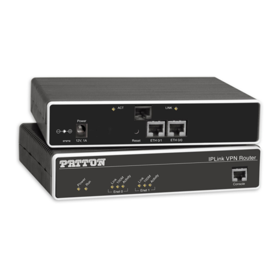
IPLink 2800 Series Getting Started Guide 1 • General information IPLink Model 2800 Series overview The IPLink Model 2800 Series Managed VPN Router (see figure 1) delivers secure, optimized communica- tions across unsecured IP networks between any enterprise headquarters and remote offices, home offices (RoHo), or mobile users. -
Page 21: Iplink 2800 Series Detailed Description
Serial WAN models. The following models come equipped with an integrated V.35 or X.21 serial WAN port and two 10/100Base-T Ethernet ports (see figure • IPLink 2821—X.21 WAN interface and two Ethernet ports • IPLink 2835—V.35 WAN interface and two Ethernet ports •... -
Page 22: Ethernet Wan Models
IPLink 2800 Series Getting Started Guide 1 • General information IPLink 2805 10/100Base-T Ethernet WAN port 0/0 Ethernet LAN ports 0/1 – 0/4 IPLink 2802 10/100Base-T Ethernet ports 0/1 and 0/0 Figure 3. IPLink 2800 Series 10Base-T Ethernet port connectors Ethernet WAN models. -
Page 23: Model Code Extensions
IPLink 2800 Series Getting Started Guide 1 • General information lnternal power supply connector accepts 100–240 VAC, 50/60 Hz, up to 1 A External power supply connector accepts 12 VDC, 1 A, from external AC adapter (some models accept +5VDC, see Appendix B, “Specifications” for details) Figure 4. -
Page 24: Ports Descriptions
IPLink 2800 Series Getting Started Guide 1 • General information Ports descriptions The IPLink 2800 Series rear-panel ports are described in table Table 2. Rear panel ports Port Location Description Rear panel RJ-45 connectors (see on page 21 and on page 22) 10/100 Ethernet figure 2 figure 3... -
Page 25: Applications Overview
IPLink 2800 Series Getting Started Guide 1 • General information Note For LED descriptions, refer to chapter 9, “LEDs status and monitor- ing” on page 114. Applications overview Patton’s IPLink managed VPN routers deliver the features you need for secure, optimized communication over non-secured IP networks. -
Page 26: Corporate Multi-Function Virtual Private Network
IPLink 2800 Series Getting Started Guide 1 • General information In this specific application, all traffic between the branch and corporate offices is carried in an IPSec tunnel. All of the IPSec VPN traffic is encapsulated in Frame Relay for transport over the Frame Relay service network. The serial port is configured for Frame Relay. - Page 27 IPLink 2800 Series Getting Started Guide 1 • General information IPLink VPN router. Each remote site can take advantage of the most convenient and locally available interface the WAN service can offer, whether X.21, or V.35. The corporate multi-function application carries two types of traffic between each remote office and corpo- rate’s central office: •...
-
Page 28: Hardware Installation
Chapter 2 Hardware installation Chapter contents Planning the installation ............................30 Installation checklist ............................31 Site log ................................32 Network information .............................32 Network Diagram .............................32 IP related information ............................32 Software tools ..............................32 Power source ..............................32 Location and mounting requirements ......................33 Installing the VPN router .............................33 Mounting the VPN router ..........................33... -
Page 29: Planning The Installation
IPLink 2800 Series Getting Started Guide 2 • Hardware installation Planning the installation Before you start the actual installation, we strongly recommend that you gather all the information you will need to install and setup the device. See table 3 for an example of what pre-installment checks you might need to carry out. -
Page 30: Installation Checklist
IPLink 2800 Series Getting Started Guide 2 • Hardware installation Installation checklist The installation checklist (see table 3) lists the tasks for installing an IPLink 2800 Series VPN Router. Make a copy of this checklist and mark the entries as you complete each task. For each IPLink 2800 Series VPN Router, include a copy of the completed checklist in your site log. -
Page 31: Site Log
IPLink 2800 Series Getting Started Guide 2 • Hardware installation Site log Patton recommends that you maintain a site log to record all actions relevant to the system, if you do not already keep such a log. Site log entries should include information such as listed in table Table 4. -
Page 32: Location And Mounting Requirements
IPLink 2800 Series Getting Started Guide 2 • Hardware installation Location and mounting requirements The IPLink VPN Router is intended to be placed on a desktop or similar sturdy, flat surface that offers easy access to the cables. Allow sufficient space at the rear of the chassis for cable connections. Additionally, you should consider the need to access the unit for future upgrades and maintenance. -
Page 33: Installing The Serial Wan Cable
IPLink 2800 Series Getting Started Guide 2 • Hardware installation connected to the IPLink’s Ethernet ports (see table 5 for port pin-out listing) via a cable terminated with RJ-45 plugs. Table 5. Ethernet 10/100Base-T (RJ-45) port pin-outs Signal Note Pins not listed are not used. Straight-through cable RJ-45, male RJ-45, male... -
Page 34: Installing The V.35 Interface Cable
IPLink 2800 Series Getting Started Guide 2 • Hardware installation • E1 (Dual coaxial connectos)—Model 2803, see section “Installing the E1 dual coaxial cables” on page 37 for details on installing the coaxial cables Installing the V.35 interface cable. The IPLink Model 2835 comes with a V.35 interface presented on a DB- 25 female connector (see figure V.35 serial port connector... -
Page 35: Installing The X.21 Interface Cable
IPLink 2800 Series Getting Started Guide 2 • Hardware installation The router’s V.35 interface is wired as a DTE. No DCE configuration is possible. If you are directly connecting the router’s V.35 interface to third-party equipment that cannot be configured as a DCE, you must use a tail- circuit cable. -
Page 36: Installing The T1/E1 Twisted Pair Cables
IPLink 2800 Series Getting Started Guide 2 • Hardware installation The signal pin-outs for the Model 2821 X.21 interface are shown in table Table 7. Signal pin-outs for the X.21 interface on the IPLink 2800 Signal Signal Frame Ground Signal Ground TXDa TXDb CNTa... -
Page 37: Installing The E1 Dual Coaxial Cables
IPLink 2800 Series Getting Started Guide 2 • Hardware installation Note Pins not listed are not used. Hazardous network voltages are present in the PRI cables. If you detach the cable, detach the end away from the IPLink first to avoid possible electric shock. -
Page 38: Connecting To External Power Source
IPLink 2800 Series Getting Started Guide 2 • Hardware installation Connecting to external power source The VPN Router comes with one of the following power supply options as best-suited to the expected installa- tion environment: • 120/140VAC internal power supply (designated by the model code extension UI) •... -
Page 39: Vpn Router Front Panel Leds And Console Port Locations (Iplink 2835 Shown)
IPLink 2800 Series Getting Started Guide 2 • Hardware installation The UI and EUI power supplies automatically adjust to accept an input voltage from 100 to 240 VAC (50/60 Hz). Verify that the proper voltage is present before plugging the CAUTION power cord into the receptacle. -
Page 40: Getting Started With The Iplink Managed Vpn Router
Chapter 3 Getting started with the IPLink Managed VPN Router Chapter contents Introduction ................................42 1. Configure IP address ............................43 Power connection and default configuration ....................43 Connect with the serial interface ........................43 Login ................................44 Changing the IP address ..........................44 2. Connect the IPLink VPN Router to the network....................45 3. -
Page 41: Introduction
IPLink 2800 Series Getting Started Guide 3 • Getting started with the IPLink Managed VPN Router Introduction This chapter leads you through the basic steps to set up a new IPLink VPN Router. Figure 9 show the main steps for setting up a new IPLink VPN Router. Configure IP address PC or workstation Serial... -
Page 42: Configure Ip Address
IPLink 2800 Series Getting Started Guide 3 • Getting started with the IPLink Managed VPN Router 1. Configure IP address Power connection and default configuration First the IPLink VPN Router must be connected to the mains power supply with the power cable. Wait until LED stops blinking and lights constantly. -
Page 43: Login
IPLink 2800 Series Getting Started Guide 3 • Getting started with the IPLink Managed VPN Router • 1 stop bit • No flow control Login Accessing your IPLink VPN Router via the local console port (or via a Telnet session) causes the login screen to display. -
Page 44: Connect The Iplink Vpn Router To The Network
IPLink 2800 Series Getting Started Guide 3 • Getting started with the IPLink Managed VPN Router 2. Connect the IPLink VPN Router to the network Depending whether you connect the IPLink VPN Router to a host directly or via a hub or switch either straight-through wired or cross-over cables must be used (see figure 11). - Page 45 IPLink 2800 Series Getting Started Guide 3 • Getting started with the IPLink Managed VPN Router After the IPLink VPN Router has been rebooted the new start up configuration will be activated. 172.16.1.99(if-ip)[eth0]#reload Running configuration has been changed. Do you want to copy the 'running-config' to the 'startup-config'? Press 'yes' to store, 'no' to drop changes : no Press 'yes' to restart, 'no' to cancel : yes The system is going down...
-
Page 46: Serial Port Configuration
Chapter 4 Serial port configuration Chapter contents Introduction ................................48 Serial port configuration task list ...........................48 Disabling an interface .............................48 Enabling an interface ............................49 Configuring the encapsulation for Frame Relay ....................50 Enter Frame Relay mode ..........................51 Configuring the LMI type ..........................51 Configuring the keep-alive interval .........................52 Entering Frame Relay PVC configuration mode... -
Page 47: Introduction
IPLink 2800 Series Getting Started Guide 4 • Serial port configuration Introduction This chapter provides an overview of the serial port and describes the tasks involved in its configuration through the IPLink router, it includes the following sections: • Serial port configuration task list •... -
Page 48: Enabling An Interface
IPLink 2800 Series Getting Started Guide 4 • Serial port configuration Note Use the no shutdown command to enable the serial interface after the configuration procedure. This procedure describes how to shut down a serial interface Mode: Administrator execution Step Command Purpose node (cfg)#port serial slot port... -
Page 49: Configuring The Encapsulation For Frame Relay
IPLink 2800 Series Getting Started Guide 4 • Serial port configuration Example: Enabling an interface The example shows how to enable the built-in serial interface on slot 0 and port 0 of an IPLink router. Check that State is set to OPENED in the command output of show port serial 2800(cfg)#port serial 0 0 2800(prt-ser)[0/0]#no shutdown... -
Page 50: Enter Frame Relay Mode
IPLink 2800 Series Getting Started Guide 4 • Serial port configuration Transmit Edge : normal Port Type : DTE CRC Type : CRC-16 Max Frame Length: 2048 Recv Threshold Encapsulation : framerelay Enter Frame Relay mode This section describes how to configure Frame Relay on the serial interface of an IPLink router, after setting the basic serial interface parameters according to the previous sections. -
Page 51: Configuring The Keep-Alive Interval
IPLink 2800 Series Getting Started Guide 4 • Serial port configuration 2800(cfg)#port serial 0 0 2800(prt-ser)[0/0]#framerelay 2800(frm-rel)[0/0]#lmi-type ansi Configuring the keep-alive interval A keep-alive interval must be set to configure the LMI. By default, this interval is 10 seconds and, according to the LMI protocol, must be less than the corresponding interval on the switch. -
Page 52: Configuring The Pvc Encapsulation Type
IPLink 2800 Series Getting Started Guide 4 • Serial port configuration Mode: Frame Relay Step Command Purpose node (frm-rel)[ slot/port ]#pvc dlci Enters the PVC configuration mode by assigning a DLCI number to be used on the specified sub interface Example: Entering Frame Relay PVC configuration mode The following example enters the configuration mode for PVC with the assigned DLCI of 1 for Frame Relay over the serial interface on slot 0 and port 0 of an IPLink router. -
Page 53: Ip Interface Wan Is Bound To Pvc 1 On Port Serial 0 0
IPLink 2800 Series Getting Started Guide 4 • Serial port configuration Frame Relay PVC. If serial Frame Relay PVC shall be used as WAN access, a suitable name for the logical IP interface could be wan as in figure 12 below. -
Page 54: Enabling A Frame Relay Pvc
IPLink 2800 Series Getting Started Guide 4 • Serial port configuration Enabling a Frame Relay PVC After binding Framerelay PVC to an ip interface it must be enabled for packet processing. This procedure acti- vates the PVC by opening the bound ip interface. This procedure describes how to enable Framerelay PVC for packet processing Mode: PVC Step... -
Page 55: Displaying Serial Port Information
IPLink 2800 Series Getting Started Guide 4 • Serial port configuration 2800(frm-rel)[0/0]#pvc 1 2800(pvc)[1]#shutdown Check the PVC 1 status by using and verify that the entry shutdown occurs in the con- show running-config figuration part responsible for this PVC. 2800(pvc)[1]#show running-config Running configuration: #----------------------------------------------------------------# # 2500... -
Page 56: Displaying Frame Relay Information
IPLink 2800 Series Getting Started Guide 4 • Serial port configuration Displaying Frame Relay information Since Frame Relay configuration for the serial interface is complex and requires many commands, it is helpful to list the frame relay configuration on screen. This procedure describes how to display the Frame Relay configuration settings for the serial interface. -
Page 57: Integrated Service Access
IPLink 2800 Series Getting Started Guide 4 • Serial port configuration Internet Multi Multi Service Service Provider PVC 1 Provider IPLink Leased Line Node Modem Modem Router 2300 Network V.35 PVC 2 Provider Provider Figure 13. Typical Integrated Service Access Scenario with dedicated PVCs Integrated service access The example in figure 13... -
Page 58: Ip Context With Logical Ip Interfaces Bound To Ethernet Port, Serial Port Pvc 1 And Pvc 2
IPLink 2800 Series Getting Started Guide 4 • Serial port configuration Port IP interface Serial PVC 1 external 192.168.2.1 IP interface Port Context Ethernet “router” 192.168.1.1 192.168.3.1 Port IP interface Serial PVC 2 external Figure 14. IP Context with logical IP interfaces bound to Ethernet port, serial port PVC 1 and PVC 2 The related IP, serial interface and Frame Relay configuration procedure is listed below. - Page 59 IPLink 2800 Series Getting Started Guide 4 • Serial port configuration 5. Configure the introduced PVCs. 2800(frm-rel)[0/0]#pvc 1 2800(pvc)[1]#encapsulation rfc1490 2800(pvc)[1]#bind interface external router 2800(pvc)[1]#no shutdown 2800(pvc)[1]#pvc 2 2800(pvc)[2]#encapsulation rfc1490 2800(pvc)[2]#bind interface internal router 2800(pvc)[2]#no shutdown … 6. Check that the Frame Relay settings are correct. 2800(frm-rel)[0/0]#show framerelay Framerelay Configuration: Port...
-
Page 60: T1/E1 Port Configuration
Chapter 5 T1/E1 port configuration Chapter contents Introduction ................................62 T1/E1 port configuration task list..........................62 Enable/Disable T1/E1 port ..........................62 Configuring T1/E1 port-type ..........................63 Configuring T1/E1 clock-mode ........................63 Configuring T1/E1 line-code ..........................63 Configuring T1/E1 framing ..........................64 Configuring T1/E1 line-build-out (T1 only) ....................64 Configuring T1/E1 used-connector (E1 only) ....................64 Configuring T1/E1 application mode... -
Page 61: Introduction
IPLink 2800 Series Getting Started Guide 5 • T1/E1 port configuration Introduction This chapter provides an overview of the T1/E1 WAN port, their characteristics and describes the configura- tion tasks. The model 2803 has a T1/E1 WAN port on the rear panel of the unit. The T1 version (Model 2803T) has an RJ-48C connector, and the E1 version (Model 2803K) offers the user connectivity via either the RJ-48C or dual coaxial connectors. -
Page 62: Configuring T1/E1 Port-Type
IPLink 2800 Series Getting Started Guide 5 • T1/E1 port configuration Mode: port e1t1 <slot> <port> Step Command Purpose [ name ] (prt-e1t1)[slot/port]# [no] Enable/Disable the T1/E1 port. Default: shutdown (which is disabled) shutdown Configuring T1/E1 port-type The T1/E1 Port can either work in T1 or in E1 (G.704) mode. This mode can be changed dynamically as long as no encapsulation or encapsulation ‘hdlc’... -
Page 63: Configuring T1/E1 Framing
IPLink 2800 Series Getting Started Guide 5 • T1/E1 port configuration Configuring T1/E1 framing Four framing formats are available for selection on the T1/E1 port. Unframed can only be used if the encapsu- lation is set for hdlc. All other currently available upper layer (encapsulation) protocols do not run in unframed mode, but in one of the framed modes. -
Page 64: Configuring T1/E1 Application Mode
IPLink 2800 Series Getting Started Guide 5 • T1/E1 port configuration Configuring T1/E1 application mode The T1/E1 port can be configured to work in either short-haul or in long-haul mode. Short-haul is the default application and should be used for transmission distances up to 180m/600ft. For transmission distances up to 1800m/6000ft, select the long-haul application. -
Page 65: Configuring Channel-Group Timeslots
IPLink 2800 Series Getting Started Guide 5 • T1/E1 port configuration tion “Configuring T1/E1 encapsulation”.) On creating a new channel-group the channel-group configuration mode is immediately entered. To remove an existing channel-group the ‘no’ form of the command has to be used. -
Page 66: Configuring Hdlc Crc-Type
IPLink 2800 Series Getting Started Guide 5 • T1/E1 port configuration tion mode the encapsulation must be set to ‘hdlc’ as well followed by configuring at least one timeslot per the ‘timeslots’ command. Mode: port e1t1 <slot> <port> Step Command Purpose [ name ] (prt-e1t1)[slot/port]# hdlc Entering the hdlc configuration mode... -
Page 67: Example 1: Frame Relay Without A Channel-Group
IPLink 2800 Series Getting Started Guide 5 • T1/E1 port configuration Example 1: Frame Relay without a channel-group port e1t1 0 0 port-type e1 framing crc4 encapsulation hdlc hdlc encapsulation framerelay framerelay lmi-type itu pvc 100 encapsulation rfc1490 bind interface pvc100 router no shutdown port e1t1 0 0 no shutdown... -
Page 68: Example 2: Framerelay With A Channel-Group
IPLink 2800 Series Getting Started Guide 5 • T1/E1 port configuration Example 2: Framerelay with a channel-group port e1t1 0 0 port-type e1 framing crc4 encapsulation channelized channel-group myGroup timeslots 13-17 encapsulation hdlc hdlc encapsulation framerelay framerelay lmi-type itu pvc 100 encapsulation rfc1490 bind interface pvc100 router no shutdown... -
Page 69: Vpn Configuration
Chapter 6 VPN configuration Chapter contents Introduction ................................76 Authentication ..............................76 Encryption ..............................76 Transport and tunnel modes ...........................77 VPN configuration task list ...........................77 Creating an IPsec transformation profile ......................77 Creating an IPsec policy profile ........................78 Creating/modifying an outgoing ACL profile for IPsec ...................80 Configuration of an IP interface and the IP router for IPsec ................81... -
Page 70: Introduction
IPLink 2800 Series Getting Started Guide 6 • VPN configuration Introduction This chapter describes how to configure the VPN connections between two IPLink routers or between an IPLink and a third-party device. A virtual private network (VPN) is a private data network that uses the public telecommunications infrastruc- ture, maintaining privacy through the use of a tunneling protocol and security procedures. -
Page 71: Transport And Tunnel Modes
IPLink 2800 Series Getting Started Guide 6 • VPN configuration Transport and tunnel modes The mode determines the payload of the ESP packet and hence the application: • Transport mode: Encapsulates only the payload of the original IP packet, but not its header, so the IPsec peers must be at the endpoints of the communications link. -
Page 72: Creating An Ipsec Policy Profile
IPLink 2800 Series Getting Started Guide 6 • VPN configuration Creating an IPsec policy profile The IPsec policy profile supplies the keys for the encryption and/or the authenticators for the authentication, the security parameters indexes (SPIs), and IP address of the peer of the secured communication. Furthermore, the profile defines which IPsec transformation profile to apply and whether transport or tunnel mode shall be most effective. - Page 73 IPLink 2800 Series Getting Started Guide 6 • VPN configuration Mode: Configure Step Command Purpose Creates the IPsec policy profile name node (cfg)#profile ipsec-policy-man- ual name Selects the IPsec transformation profile to be node (pf-ipstr)[name]#use profile ipsec-transform name applied node (pf-ipstr)[ name ]#session-key Sets a key for encryption or an authenticator for authentication, either for inbound or outbound optional...
-
Page 74: Creating/Modifying An Outgoing Acl Profile For Ipsec
IPLink 2800 Series Getting Started Guide 6 • VPN configuration Example: Create an IPsec policy profile The following example defines a profile for AES-encryption at a key length of 128. 2800(cfg)#profile ipsec-policy-manual ToBurg 2800(pf-ipsma)[ToBurg]#use profile ipsec-transform AES_128 2800(pf-ipsma)[ToBurg]#session-key inbound esp-encryption 1234567890ABCDEF1234567890ABCDEF 2800(pf-ipsma)[ToBurg]#session-key outbound esp-encryption FEDCBA0987654321FEDCBA0987654321 2800(pf-ipsma)[ToBurg]#spi inbound esp 1111... -
Page 75: Configuration Of An Ip Interface And The Ip Router For Ipsec
IPLink 2800 Series Getting Started Guide 6 • VPN configuration Configuration of an IP interface and the IP router for IPsec The IP interface that provides connectivity to the IPsec peer, must now activate the outgoing ACL profile con- figured in the previous section. Furthermore, the IP router must have a route for the remote network that points to the respective IP interface. -
Page 76: Debugging Ipsec
IPLink 2800 Series Getting Started Guide 6 • VPN configuration Example: Display IPsec transformation profiles 2800(cfg)#show profile ipsec-transform IPSEC transform profiles: Name: AES_128 ESP Encryption: AES-CBC, Key length: 128 Example: Display IPsec policy profiles 2800(cfg)#show profile ipsec-policy-manual Manually keyed IPsec policy profiles: Name: ToBurg, Peer: 200.200.200.1, Mode: tunnel, transform-profile: AES_128 ESP SPI Inbound: 1111, Outbound: 2222 ESP Encryption Key Inbound: 1234567890ABCDEF1234567890ABCDEF... -
Page 77: Sample Configurations
IPLink 2800 Series Getting Started Guide 6 • VPN configuration MANUAL ToBurg Tunnel 200.200.200.1 1111 AES-CBC 128 3622/unlimited 19047/unlimited OUT MANUAL ToBurg Tunnel 200.200.200.1 2222 AES-CBC 128 2857/unlimited 19047/unlimited Sample configurations The following sample configurations establish IPsec connections between an IPLink and a Cisco router. To interconnect two IPLink routers instead, derive the configuration for the second IPLink by doing the following modifications: •... -
Page 78: Cisco Router Configuration
IPLink 2800 Series Getting Started Guide 6 • VPN configuration use profile acl VPN_In in use profile acl VPN_Out out context ip router route 0.0.0.0 0.0.0.0 200.200.200.1 0 route 172.16.0.0 255.255.0.0 WAN 0 Cisco router configuration crypto ipsec transform-set DES esp-des crypto map VPN_DES local-address FastEthernet0/1 crypto map VPN_DES 10 ipsec-manual set peer 200.200.200.2... -
Page 79: Cisco Router Configuration
IPLink 2800 Series Getting Started Guide 6 • VPN configuration Cisco router configuration crypto ipsec transform-set AES_SHA1 ah-sha-hmac esp-aes 256 crypto map VPN_AES_SHA1 local-address FastEthernet0/1 crypto map VPN_AES_SHA1 10 ipsec-manual set peer 200.200.200.2 set session-key inbound esp 6666 cipher FEDCBA0987654321FEDCBA0987654321FEDCBA0987654321FEDCBA0987654321 set session-key outbound esp 5555 cipher 1234567890ABCDEF1234567890ABCDEF1234567890ABCDEF1234567890ABCDEF set session-key inbound ah 4444 FEDCBA0987654321FEDCBA0987654321FEDCBA09... - Page 80 IPLink 2800 Series Getting Started Guide 6 • VPN configuration match address 110 For the remainder of the configuration (see above), just change the name of the IPsec policy profile in the ACL profile VPN_Out. Sample configurations...
-
Page 81: Access Control List Configuration
Chapter 7 Access control list configuration Chapter contents Introduction ................................88 About access control lists ............................88 What access lists do ............................88 Why you should configure access lists ......................88 When to configure access lists .........................89 Features of access control lists .........................89 Access control list configuration task list........................90 Mapping out the goals of the access control list ....................90... -
Page 82: Introduction
IPLink 2800 Series Getting Started Guide 7 • Access control list configuration Introduction This chapter provides an overview of IP Access Control Lists and describes the tasks involved in configuring them through the IPLink router. This chapter includes the following sections: •... -
Page 83: When To Configure Access Lists
IPLink 2800 Series Getting Started Guide 7 • Access control list configuration For example, access lists can allow one host to access a part of your network, and prevent another host from accessing the same area. In figure 15 host A is allowed to access the Human Resources network and host B is prevented from accessing the Human Resources network. -
Page 84: Access Control List Configuration Task List
IPLink 2800 Series Getting Started Guide 7 • Access control list configuration • All access control lists have an implicit deny ip any any at the end. A packet that does not match the criteria of the first statement is subjected to the criteria of the second statement and so on until the end of the access control list is reached, at which point the packet is dropped. -
Page 85: Creating An Access Control List Profile And Enter Configuration Mode
IPLink 2800 Series Getting Started Guide 7 • Access control list configuration Before you begin to enter the commands that create and configure the IP access control list, be sure that you are clear about what you want to achieve with the list. Consider whether it is better to deny specific accesses and permit all others or to permit specific accesses and deny all others. - Page 86 IPLink 2800 Series Getting Started Guide 7 • Access control list configuration Mode: Profile access control list Step Command Purpose node (pf-acl)[ name ]#deny ip { src src-wildcard | any | host Creates an IP access of control list src } { dest dest-wildcard | any | host dest } [cos group ] entry that denies access defined according to the command options...
-
Page 87: Adding An Icmp Filter Rule To The Current Access Control List Profile
IPLink 2800 Series Getting Started Guide 7 • Access control list configuration Adding an ICMP filter rule to the current access control list profile The command permit or deny are used to define an ICMP filter rule. Each ICMP filter rule represents an ICMP access of control list entry. - Page 88 IPLink 2800 Series Getting Started Guide 7 • Access control list configuration Where the syntax is as following: Keyword Meaning The source address to be included in the rule. An IP address in dotted-decimal-format, e.g. 64.231.1.10. A wildcard for the source address. Expressed in dotted-decimal format this value specifies src-wildcard which bits are significant for matching.
-
Page 89: Adding A Tcp, Udp Or Sctp Filter Rule To The Current Access Control List Profile
IPLink 2800 Series Getting Started Guide 7 • Access control list configuration The same effect can also be obtained by using the simpler message name option. See the following example. 2800(cfg)#profile acl WanRx 2800(pf-acl)[WanRX]#deny icmp any any msg echo 2800(pf-acl)[WanRX]#exit 2800(cfg)# Adding a TCP, UDP or SCTP filter rule to the current access control list profile The commands permit or deny are used to define a TCP, UDP or SCTP filter rule. - Page 90 IPLink 2800 Series Getting Started Guide 7 • Access control list configuration Where the syntax is: Keyword Meaning The source address to be included in the rule. An IP address in dotted-decimal-format, e.g. 64.231.1.10. A wildcard for the source address. Expressed in dotted-decimal format this value specifies src-wildcard which bits are significant for matching.
-
Page 91: Binding And Unbinding An Access Control List Profile To An Ip Interface
IPLink 2800 Series Getting Started Guide 7 • Access control list configuration Binding and unbinding an access control list profile to an IP interface The command use is used to bind an access control list profile to an IP interface. This procedure describes how to bind an access control list profile to incoming packets on an IP interface Mode: Profile access control list Step... -
Page 92: Displaying An Access Control List Profile
IPLink 2800 Series Getting Started Guide 7 • Access control list configuration Unbind an access control list profile from an interface. 2800(cfg)#context ip router 2800(cfg-ip)[router]#interface wan 2800(cfg-if)[wan]#no use profile acl in Note When unbinding an access control list profile the name argument is not required, since only one incoming and outgoing access control list can be active at the same time on a certain IP interface. - Page 93 IPLink 2800 Series Getting Started Guide 7 • Access control list configuration Mode: Interface Step Command Purpose Selects the IP router context node (cfg)#context ip router node (ctx-ip)[router]#interface if-name Selects IP interface if-name for which access control list profile shall be debugged node (if-ip)[ if-name ]#debug acl {in | out} [level] Enables access control list debug monitor with a certain debug level for the selected...
-
Page 94: Examples
IPLink 2800 Series Getting Started Guide 7 • Access control list configuration Examples Denying a specific subnet Figure 16 shows an example in which a server attached to network 172.16.1.0 shall not be accessible from outside networks connected to IP interface lan of the IPLink device. To prevent access, an incoming filter rule named Jamming is defined, which blocks any IP traffic from network 172.16.2.0 and has to be bound to IP interface lan. -
Page 95: Link Scheduler Configuration
Chapter 8 Link scheduler configuration Chapter contents Introduction ................................102 Configuring access control lists..........................102 Configuring quality of service (QoS) ........................103 Applying scheduling at the bottleneck ......................103 Using traffic classes ............................103 Introduction to Scheduling ...........................104 Priority ..............................104 Weighted fair queuing (WFQ) ........................104 Shaping ..............................105 Burst tolerant shaping or wfq... -
Page 96: Introduction
IPLink 2800 Series Getting Started Guide 8 • Link scheduler configuration Introduction This chapter describes how to use and configure the IPLink Quality of Service (QoS) features. Refer to 7, “Access control list configuration” on page 81 for more information on the use of access control lists. This chapter includes the following sections: •... -
Page 97: Configuring Quality Of Service (Qos)
IPLink 2800 Series Getting Started Guide 8 • Link scheduler configuration NAPT Profile Service Policy Profile router Context use command use command Interfaces Profile bind command bind command Circuit Ports Figure 17. IP context and related elements Configuring quality of service (QoS) In the IPLink 2800, the link scheduler enables the definition of QoS profiles for network traffic on a certain interface, as shown in figure... -
Page 98: Introduction To Scheduling
IPLink 2800 Series Getting Started Guide 8 • Link scheduler configuration can be used to mark a specific packet type for the other network nodes. By default the traffic-class tag is empty. Refer to figure 18 on page 98 when using the ACL to classify traffic. It illustrates the sequence of processing stages every routed packet passes. -
Page 99: Shaping
IPLink 2800 Series Getting Started Guide 8 • Link scheduler configuration Each traffic-class is in fact assigned a relative weight, which is used to share the bandwidth among the currently active classes. Patton recommends that you specify the weight as percent which is best readable. Shaping There is another commonly used way to assign bandwidth. -
Page 100: Quick References
IPLink 2800 Series Getting Started Guide 8 • Link scheduler configuration Mode priority critical_q min. 30% min. 40% Level_1 min. 30% Mail Low_Priority Default Mode Shaper Define 2nd level Define 1st level Use arbiter on arbiter arbiter an interface Figure 19. Example of Hierarchical Scheduling Quick references The following sections provide a minimal “standard”... -
Page 101: Command Cross Reference
IPLink 2800 Series Getting Started Guide 8 • Link scheduler configuration • “modem-512” is the title of the profile which is referred to when installing the scheduler • “rate-limit 512” allows no more than 512 kbit/sec to pass which avoids queueing in the modem. •... -
Page 102: Defining The Access Control List Profile
IPLink 2800 Series Getting Started Guide 8 • Link scheduler configuration • Displaying link scheduling profile information (see page 112) • Enable statistics gathering (see page 112) Profile Packet Classification Predefined Classes Different Types (Classes) of Traffic The service-policy profile defines the arbitration mode and order in which packets of different... -
Page 103: Creating An Access Control List
IPLink 2800 Series Getting Started Guide 8 • Link scheduler configuration Some types of packets you do not have to tag with ACL. Voice and data packets from of for the IPLink itself are automatically tagged with predefined traffic-class names: Predefined internal classes for data are: •... -
Page 104: Creating A Service Policy Profile
IPLink 2800 Series Getting Started Guide 8 • Link scheduler configuration Mode: Configure Step Command Purpose node (cfg)#profile acl name Creates a new access control list profile named name node (pf-acl)[ name ]#permit ip host ip-address any traffic-class Creates an IP access con- class-name trol list entry that permits access for host at IP... - Page 105 IPLink 2800 Series Getting Started Guide 8 • Link scheduler configuration profile service-policy <profile-name> link rate, arbitration common settings common parameters source traffic-class <x> bandwidth, packet mark settings for class x queue-size, etc. source traffic-class <y> settings for class y source traffic-class default settings for all other traffic-classes not listed...
-
Page 106: Specifying The Handling Of Traffic-Classes
IPLink 2800 Series Getting Started Guide 8 • Link scheduler configuration At a some point the source traffic-class default must be listed. This class must be present, because it defines how packets, which do not belong to any of the traffic-classes listed in the profile are to be handled. When all listed “traffic-classes”... -
Page 107: Defining The Bit-Rate
IPLink 2800 Series Getting Started Guide 8 • Link scheduler configuration Mode: Source Command Purpose node (src)[ name ]#share percentage Defines fair queuing weight (relative to other sources) to percent- age for the selected class or policy name Defining the bit-rate The command rate is used with shaper link arbitration to assign the (average) bit-rate to the selected source. -
Page 108: Specifying The Precedence Field
IPLink 2800 Series Getting Started Guide 8 • Link scheduler configuration The type-of-service (TOS) byte in an IP header specifies precedence (priority) and type of service (RFC791, RFC1349). The precedence field is defined by the first three bits and supports eight levels of priority. The next four bits—which are set by the command—determine the type-of-service (TOS). -
Page 109: Specifying Layer 2 Marking
IPLink 2800 Series Getting Started Guide 8 • Link scheduler configuration “traffic-class” number called. With IPLink you can inspect the DSCP value in the ACL rules and modify the DSCP value with the link scheduler command. set ip dscp Note When configuring service differentiation on the IPLink router, ensure that codepoint settings are arranged with the service provider. -
Page 110: Defining Random Early Detection
IPLink 2800 Series Getting Started Guide 8 • Link scheduler configuration Defining random early detection The command is used to request random early detection (RED). When a queue carries lots of random-detect TCP transfers that last longer than simple web requests, there is a risk that TCP flow-control might be ineffi- cient. -
Page 111: Devoting The Service Policy Profile To An Interface
IPLink 2800 Series Getting Started Guide 8 • Link scheduler configuration Devoting the service policy profile to an interface Any service policy profile needs to be bound to a certain IP interface to get activated. According the terminol- ogy of IPLink a service policy profile is used on a certain IP interface, as shown in figure Service Policy... -
Page 112: Displaying Link Arbitration Status
IPLink 2800 Series Getting Started Guide 8 • Link scheduler configuration 2800>enable 2800#configure 2800(cfg)#context ip router 2800(ctx-ip)[router]#interface wan 2800(if-ip)[wan]#use profile service-policy Voice_Prio out Displaying link arbitration status command displays link arbitration status. This command supports the optional show service-policy argument interface that select a certain IP interface. - Page 113 IPLink 2800 Series Getting Started Guide 8 • Link scheduler configuration The command has optional values (in the range of 1 to 4) that define the level of detail (see table 13). Table 13. Values defining detail of the queuing statistics Optional Value Implication on Command Output Statistic gathering is switched off...
-
Page 114: Leds Status And Monitoring
Chapter 9 LEDs status and monitoring Chapter contents Status LEDs................................121... -
Page 115: Status Leds
IPLink 2800 Series Getting Started Guide 9 • LEDs status and monitoring Status LEDs This chapter describes IPLink gateway router front panel LEDs. Figure 24 shows IPLink 2800 Series LEDs. LED definitions are listed in table 14 on page 115. IPLink 2805 IPLink VPN Router IPLink 2800... -
Page 116: Contacting Patton For Assistance
Chapter 10 Contacting Patton for assistance Chapter contents Introduction ................................123 Contact information............................123 Patton Support Headquarters in the USA .....................123 Alternate Patton support for Europe, Middle Ease, and Africa (EMEA) ............123 Warranty Service and Returned Merchandise Authorizations (RMAs)..............123 Warranty coverage ............................123 Out-of-warranty service ...........................124 Returns for credit... -
Page 117: Introduction
RAS warranty and obtaining a return merchandise authorization (RMA). Contact information Patton Electronics offers a wide array of free technical services. If you have questions about any of our other products we recommend you begin your search for answers by using our technical knowledge base. Here, we have gathered together many of the more commonly asked questions and compiled them into a searchable database to help you quickly solve your problems. -
Page 118: Out-Of-Warranty Service
Shipping instructions The RMA number should be clearly visible on the address label. Our shipping address is as follows: Patton Electronics Company RMA#: xxxx 7622 Rickenbacker Dr. - Page 119 Appendix A Compliance information Chapter contents Compliance .................................120 ................................120 Safety ................................120 PSTN Regulatory ............................120 Radio and TV Interference (FCC Part 15) ......................120 CE Declaration of Conformity ..........................120 Authorized European Representative ........................121 FCC Part 68 (ACTA) Statement (Model 2803 only)...................121 Industry Canada Notice (Model 2803 only) ......................121...
-
Page 120: A Compliance Information
IPLink 2800 Series Getting Started Guide A • Compliance information Compliance • FCC Part 15, Class A • EN55022, Class A • EN55024 Safety • UL 60950-1/CSA C22.2 N0.60950-1 • IEC/EN60950-1 • AS/NZS 60950-1 PSTN Regulatory • ACTA Part 68 (Model 2803) •... -
Page 121: Authorized European Representative
IPLink 2800 Series Getting Started Guide A • Compliance information Authorized European Representative D R M Green European Compliance Services Limited. Oakdene House, Oak Road Watchfield, Swindon, Wilts SN6 8TD, UK FCC Part 68 (ACTA) Statement (Model 2803 only) This equipment complies with Part 68 of FCC rules and the requirements adopted by ACTA. On the bottom side of this equipment is a label that contains—among other information—a product identifier in the format US: AAAEQ##TXXXX. - Page 122 Appendix B Specifications Chapter contents Ethernet interfaces ...............................129 Sync serial interface .............................129 T1/E1 interface (Model 2803 only)........................129 PPP support ................................129 IP services ................................130 Management ...............................130 Operating environment ............................130 Operating temperature ..........................130 Operating humidity ............................130 System .................................130 Dimensions .................................130 Power supply ...............................131 Internal AC version ............................131...
-
Page 123: B Specifications
IPLink 2800 Series Getting Started Guide B • Specifications Ethernet interfaces 10/100Base-TX Ethernet WAN port 4-port 10/100Base-TX Ethernet LAN switch (Model 2805) 10/100Base-TX Ethernet LAN port (all other models) All ports full duplex, autosensing, auto-MDIX 10/100 Full Duplex/Autosensing Ethernet RJ-45 Sync serial interface ITU-T X.21 or V.35 interface Female DB-15 and DB-25 connectors (receptacles) -
Page 124: Ip Services
IPLink 2800 Series Getting Started Guide B • Specifications PPP, PAP, CHAP, LCP, IPCP IP services IPv4 router; RIPv1, v2 (RFC 1058 and 2453) Programmable static routes ICMP redirect (RFC 792); Packet fragmentation DiffServe/ToS set or queue per header bits Packet Policing discards excess traffic 802.1p VLAN tagging IPSEC AH &... -
Page 125: Power Supply
IPLink 2800 Series Getting Started Guide B • Specifications Power supply Internal AC version Internal power supply 100–240 VAC, 50/60 Hz, 200 mA 12VDC version with External AC Power Adapter (Models 2802, 2821, 2835) Uses external AC Adaptor which provides 12VDC via barrel type connector AC Adapter Input: 90-264VAC, 47-63Hz AC Adapter Output: 12 VDC, 1.25A max Note... -
Page 126: Cabling
Appendix C Cabling Chapter contents Introduction ................................134 Serial console ..............................134 Ethernet 10Base-T and 100Base-T ........................135... -
Page 127: Introduction
IPLink 2800 Series Getting Started Guide C • Cabling Introduction This section provides information on the cables used to connect the IPLink to the existing network infrastruc- ture and to third party products. The interconnecting cables must be acceptable for external use and must be rated for the proper application with respect to volt- age, current, anticipated temperature, flammability, and CAUTION... -
Page 128: Ethernet 10Base-T And 100Base-T
IPLink 2800 Series Getting Started Guide C • Cabling Ethernet 10Base-T and 100Base-T Ethernet devices (10Base-T/100Base-T) are connected to the IPLink over a cable with RJ-45 plugs. Use a cross-over cable to a host, or a straight cable to a hub. See figure 26 (host) and figure 27... -
Page 129: Ethernet Straight-Through
IPLink 2800 Series Getting Started Guide C • Cabling Straight-through cable RJ-45, male RJ-45, male 1 Rx+ 2 Rx- 3 Tx+ 6 Tx- Figure 27. Ethernet straight-through Ethernet 10Base-T and 100Base-T... - Page 130 Appendix D Port pin-outs Chapter contents Introduction ................................138 Console port, RJ-45, EIA-561 (RS-232)......................138 Ethernet 10Base-T and 100Base-T port ......................139 Sync serial port..............................139 V.35 serial port ............................139 X.21 serial port ............................140...
-
Page 131: D Port Pin-Outs
IPLink 2800 Series Getting Started Guide D • Port pin-outs Introduction This section provides pin-out information for the ports of the IPLink router. Console port, RJ-45, EIA-561 (RS-232) The RS-232 serial console port of the IPLink is configured to operate as a DCE. View the image in figure 28 showing the RJ-45 receptacle with the numerical identification of the pin numbers and functions. -
Page 132: Ethernet 10Base-T And 100Base-T Port
IPLink 2800 Series Getting Started Guide D • Port pin-outs Ethernet 10Base-T and 100Base-T port Table 16. RJ-45 socket Signal Direction from IPLink from IPLink to IPLink to IPLink The Ethernet ports are auto-detect MDI-X. Note Pins not listed are not used. Sync serial port V.35 serial port Table 17. -
Page 133: Serial Port
IPLink 2800 Series Getting Started Guide D • Port pin-outs X.21 serial port Table 18. X.21 Female DB-15 connector X.21 Interface Pin-Out Signal Frame Ground TD-a CNTRL-a RD-a IND-a SET-a Signal Ground TD-b CNTRL-b RD-b IND-b SET-b Note Pins not labeled are not used. Sync serial port... -
Page 134: Iplink 2800 Series Factory Configuration
Appendix E IPLink 2800 Series factory configuration Chapter contents Introduction ................................142... -
Page 135: Introduction
IPLink 2800 Series Getting Started Guide E • IPLink 2800 Series factory configuration Introduction The factory configuration settings for the IPLink 2800 Series devices are as follows: #----------------------------------------------------------------# # 2800 Series # R3.xx BUILDxxxxx # 2005-01-18T00:00:00 # Factory configuration file #----------------------------------------------------------------# profile napt NAPT profile dhcp-server DHCP... -
Page 136: Installation Checklist
Appendix F Installation checklist Chapter contents Introduction ................................144... -
Page 137: Introduction
IPLink 2800 Series Getting Started Guide F • Installation checklist Introduction This appendix lists the tasks for installing an IPLink 2800 Series Managed VPN Router (see table 19). Make a copy of this checklist and mark the entries as you complete each task. For each IPLink 2800 Series Router, include a copy of the completed checklist in your site log.
Need help?
Do you have a question about the IPLink 2821 and is the answer not in the manual?
Questions and answers