Table of Contents
Advertisement
Quick Links
Advertisement
Table of Contents

Related Manuals for Speco D24GS


Summary of Contents for Speco D24GS
-
Page 3: Compliance Notice Of Fcc
Digital Video Recorder WARNING RISK OF ELECTRIC SHOCK DO NOT OPEN WARNING: TO REDUCE THE RISK OF ELECTRIC SHOCK, DO NOT REMOVE COVER (OR BACK). NO USER-SERVICEABLE PARTS INSIDE. REFER SERVICING TO QUALIFIED SERVICE PERSONNEL. The lightning flash with arrowhead symbol, within an equilateral triangle, is intended to alert the user to the presence of uninsulated "dangerous voltage"... -
Page 4: Operation Instruction
Operation Instruction Important Safeguards 1. Read Instructions 14. Damage requiring Service All the safety and operating instructions should be read before the Unplug this equipment from the wall outlet and refer servicing to appliance is operated. qualified service personnel under the following conditions: A. -
Page 5: Table Of Contents
Digital Video Recorder Table of Contents Chapter 1 — Introduction ......................1 Feature ........................... 1 Technical Overview ........................ 1 Chapter 2 — Installation ......................3 Package Contents ........................3 Required Installation Tools ....................3 Video Input......................... 3 Video Loop Through ......................4 Factory Reset Switch ...................... - Page 6 Operation Instruction Layout Button ........................12 Zoom Button ........................13 PTZ Button........................13 Enter Button ........................13 Esc Button ........................13 PTZ Control Buttons ......................13 Copy Button ........................13 Play/Stop Button ......................13 Turning on the Power ......................13 Initial Unit Setup ........................
- Page 7 Preparing the USB hard disk drive in Windows 98............85 Text-In Search Examples..................... 86 Search Example I ......................86 Search Example II ......................86 Speco Remote ........................87 Web Monitoring Mode ..................... 88 Web Search Mode ......................89 Time Overlap ........................91 Remote Setup of Network Devices ..................
- Page 8 Operation Instruction List of Illustrations Figure 1 : Typical DVR installation......................2 Figure 2 : 16-Channel DVR rear panel...................... 3 Figure 3 : 16-Channel DVR front panel..................... 9 Figure 4 : Infrared remote control......................11 Figure 5 : Login screen........................... 14 Figure 6 : Logout screen.
- Page 9 Digital Video Recorder Figure 55 : Clip-Copy screen........................80 Figure 56 : Print screen........................... 82 Figure 57 : System – Storage setup screen.................... 82...
- Page 10 Operation Instruction viii...
-
Page 11: Chapter 1 - Introduction
Digital Video Recorder Chapter 1 — Introduction Feature Your color digital video recorder (DVR) provides recording capabilities for eight or 16 camera inputs. It provides exceptional picture quality in both live and playback modes, and offers the following features: NOTE: Your DVR can record both analog CCTV video input and network video input. For a list of supported network devices (network cameras and network video transmitters), contact your installer or distributer. -
Page 12: Figure 1 : Typical Dvr Installation
Operation Instruction Your DVR supports disk mirroring functions to prevent any unexpected loss of recorded video data that might be caused by disk damage or corruption. Your DVR uses a proprietary encryption scheme making it nearly impossible to alter video. Your DVR can be used to monitor video from network video transmitters and/or network cameras, record monitored video and play back recorded video. -
Page 13: Chapter 2 - Installation
The package contains the following: Digital Video Recorder Power Cord Operation Instruction (This Document) Speco Central Software CD and Operation Instruction Rack-mount Kit Assembly Screws for Adding Hard Disk Drives SATA Cables Audio Extension Cable ... -
Page 14: Video Loop Through
Operation Instruction Video Loop Through If you would like to connect your video source to another device, you can use the Loop BNC connectors. NOTE: The Loop BNC connectors are auto terminated. Do NOT connect a cable to the Loop BNC unless it is connected to a terminated device because it will cause poor quality video. -
Page 15: Esata Port
Digital Video Recorder CAUTION: When recording video on the iSCSI device, the recoding speed might decrease and the DVR system performance might be affected if the network devices (network cameras and network video transmitters) are connected. eSATA Port An eSATA port is provided to connect external storage devices for recording or archiving video. Connect the external eSATA hard disk drive (RAID) cable to the eSATA port. -
Page 16: Audio In/Out
Operation Instruction Audio In/Out Your DVR can record audio from up to 16 sources. Connect the audio sources to Audio In 1 to Audio In 16 as needed using RCA jacks. Connect Audio Out to your amplifier. Use the provided audio extension cable to connect the audio sources to Audio In 5 to 16. -
Page 17: Power Cord Connector
Digital Video Recorder Power Cord Connector Connect the AC power cord to the DVR and then to a wall outlet. WARNING: ROUTE POWER CORDS SO THAT THEY ARE NOT A TRIPPING HAZARD. MAKE CERTAIN THE POWER CORD WILL NOT BE PINCHED OR ABRADED BY FURNITURE. DO NOT INSTALL POWER CORDS UNDER RUGS OR CARPET. - Page 18 Operation Instruction...
-
Page 19: Chapter 3 - Configuration
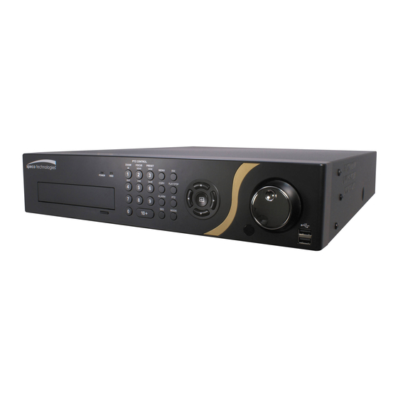
Digital Video Recorder Chapter 3 — Configuration NOTE: Your DVR should be completely installed before proceeding. Refer to Chapter 2 — Installation. Front Panel Controls Figure 3 : 16-Channel DVR front panel. Power LED HDD LED Camera Buttons Menu Button Copy Button Esc Button Play/Stop Button... -
Page 20: Menu Button
Operation Instruction Menu Button In the Live Monitoring mode and Search mode, pressing the button displays the menu icons at the top of the screen. MENU Copy Button Pressing the button allows you to copy video clips. COPY Esc Button During menu setup, pressing the button closes the current menu or setup dialog box. -
Page 21: Jog Dial
Digital Video Recorder Jog Dial When in the playback mode, you can play video forward image-by-image by turning the Jog Dial clockwise and backward image-by-image by turning the Jog Dial counterclockwise. When in the Setup mode, you can change number values by highlighting the item in the menu and turning Jog Dial clockwise or counterclockwise to increase or decrease the number. -
Page 22: Id Button
Operation Instruction NOTE: For simplicity, the button descriptions in this manual refer to the front panel buttons. ID Button If a DVR System ID is set to 0, the infrared remote control will control that DVR without any additional operations. (Refer to the System General setup screen in this chapter for further information on setting the System ID.) If the system ID is 1 to 16, you must to press the button and then press the number button (1 to 16 (+10 &... -
Page 23: Zoom Button
Digital Video Recorder Zoom Button Pressing the button zooms the current image on the screen. A PIP with a rectangle temporarily displays showing ZOOM what area of the screen has been enlarged. You can use the arrow buttons to move the rectangle to another area. PTZ Button Pressing the button enters the PTZ (Pan/Tilt/Zoom) mode which allows you to control properly configured cameras. -
Page 24: Setup Screen
Operation Instruction Select a User and enter the password by pressing the appropriate combination of Camera number buttons and then the button. There is no default password when logging in the admin user for the first time. Figure 5 : Login screen. NOTE: To assure the secure management of the system, setting up a password is strongly recommended. -
Page 25: System Setup
Digital Video Recorder Use the arrow keys to highlight the character you want in the name or title and press button. That character appears in the title bar and the cursor moves to the next position. Pressing toggles between the upper and lower case keyboards, backspaces, and deletes entered characters. - Page 26 Operation Instruction To upgrade the software, connect a USB device containing the upgrade package file to the DVR. Highlight Upgrade… button. The Upgrade screen appears. The screen displays the upgrade package file names that are and press the available. The “.rui” indicates that the file is for software upgrades and “.ofi” indicates that the file is for optical drive firmware upgrades.
- Page 27 Digital Video Recorder To export the system log information, connect the USB device to the DVR. Highlight Export… and press the button. Highlight the box beside File name and press the button. A virtual keyboard allows you to enter the file name. Selecting Export will save the log information in .txt file format on the USB device.
- Page 28 Operation Instruction If you selected the EZ Record, selecting the Next button starts the EZ Record. Date/Time Setup Date: Set the system date and select the date format. Time: Set the system time and select the time format. ...
- Page 29 Digital Video Recorder Record Method Setup Select the desired recording mode from: – Motion Event Record (Recommended) – Continuous & Motion Event Record – Continuous Record NOTE: You should understand each recording mode before setting the DVR’s recording method. Record Video Quality Setup ...
- Page 30 Operation Instruction Select the Finish button to finish the EZ Record and select the Go to EZ Network button to start the EZ Network. If you selected the Go to EZ Network, select the Next button to start the EZ Network.
- Page 31 Digital Video Recorder Internet Connection Select whether or not your DVR is connected to the Internet. LAN Setup Select between Auto Configuration and Manual Configuration for network configuration, and then select the Test button to test the network configuration you selected. NOTE: Selecting Auto Configuration allows the DVR to automatically obtain LAN parameters (IP address, Gateway, Subnet Mask and DNS Server address).
-
Page 32: Date/Time
Operation Instruction NOTE: The DVR name you entered should be checked by selecting Check, otherwise the DVRNS changes will not be saved. When entering no name or a name already registered on the DVRNS server, an error message displays. Select the Finish button to finish the EZ Setup. Date/Time Highlight Date/Time and press the button, and the Date/Time setup screen appears. -
Page 33: User
Digital Video Recorder NOTE: The clock will not start running until you have highlighted Save and pressed the button. Highlight the box beside Time Zone and press the button. Select your time zone from the list and press the button. Highlight Use Daylight Saving Time and press the button toggles between On and Off. -
Page 34: Figure 10 : System - User Setup Screen
You will be asked to confirm that you want to delete the User or Group. To delete the User currently logged into the DVR on a local system or a PC running Speco Central, log the user out of the system first and then delete the user. -
Page 35: Storage
PC running Speco Central. System Time Change – The user can change the system date and time on a local system or a PC running Speco Central. Data Clear – The user can clear all video data or format disks on a local system or a PC running Speco Central. -
Page 36: Monitoring
Operation Instruction The Format column displays whether the device is used for recording (Record), archiving (Archive) or not (Not Using). Not formatted indicates the device is not formatted. indicates when the device has temporary space set aside so that video clips can be saved on a DVD RW. Highlight the box in the Format column for the desired storage device and press the button. -
Page 37: Recording Setup
System events can be associated with an Alarm-Out connector, sound the DVR’s internal buzzer, and/or notify a number of different devices. NOTE: Alarm-Out action cannot be set to System and Panic Record events. For the Notify action to work, the DVR should be registered in the Speco Central (Remote Administration System). Recording Setup... -
Page 38: Figure 13 : Record - General Setup Screen
Operation Instruction Figure 13 : Record – General setup screen. Highlighting Recycle and pressing the button toggles between On and Off. In the Recycle mode, the DVR records over the oldest video data once all available storage space has been used. When Recycle is turned off, the DVR stops recording once all available storage space has been used. -
Page 39: Schedule
Digital Video Recorder Highlighting Use Panic Recording and pressing the button toggles between On and Off. Highlight the Panic Recording – Duration box and set the duration of panic recording. Panic recording will stop automatically after the preset duration as long as (Panic) in the Live Monitoring menu is not selected to stop the panic recording. -
Page 40: Figure 15 : Schedule - Settings (Advanced Mode) Setup Screen
Operation Instruction When the DVR is in the No Record mode, it will not record during the preset day and time range as long as (Panic) in the Live Monitoring menu is not selected. Use the No Record mode when you do NOT want the DVR to record during certain times. -
Page 41: Pre-Event
Digital Video Recorder NOTE: For network devices using the ONVIF Conformance Protocol, the DVR records using the profile settings designated in the DVR preset profiles. You can designate which profile to use for recording when setting up the network device. Refer to Camera – Network Camera setup screen in this chapter and Appendix – Remote Setup of Network Devices for further information on setting up the network device. -
Page 42: Archive
Operation Instruction You can turn individual cameras On or Off for pre-event recording. The image speed can be set from 1.00 to 30.00 ips (25.00 ips PAL), image quality can be selectable from Very High, High, Standard and Basic, and image resolution can be selectable from Very High (D1), High (2CIF) and Standard (CIF). -
Page 43: Event Setup
Digital Video Recorder Event Setup Motion Highlight Motion and press the button, and the Motion setup screen appears. (Local Cameras Only) Figure 18 : Event – Motion setup screen. Your DVR has built-in video motion detection. Video motion detection can be turned On or Off for each camera. Highlighting the box under the Sensitivity heading and pressing the button allows you to adjust the DVR’s sensitivity to motion for Daytime and Nighttime... -
Page 44: Alarm-In
Operation Instruction You can adjust the minimum number of detection blocks that must be activated to trigger a motion alarm. Highlighting the box under the Min. Blocks heading and pressing the button allows you to adjust the minimum number of detection blocks for Daytime and Nighttime independently. Smaller numbers provide greater sensitivity because fewer detection blocks must be activated. -
Page 45: Video Loss
Digital Video Recorder Video Loss Highlight Video Loss and press the button, and the Video Loss setup screen appears. (Local Cameras Only) Figure 20 : Event – Video Loss setup screen. Highlight the box under the Actions and press the button. -
Page 46: Text-In
Operation Instruction You can turn individual cameras On or Off for video blind detection by highlighting the camera number and pressing the button. Highlighting the box under the Sensitivity heading allows you to adjust the DVR’s sensitivity to video blind from 1 (least sensitive) to 10 (most sensitive). -
Page 47: Figure 23 : Text-In Device Screen
Digital Video Recorder Figure 23 : Text-In Device screen. Highlight the box beside Port, and press the button. Select from None, RS232, RS485, USB-Serial (1~8) and LAN (1~16). NOTE: If you have set the Port as None, you will not be able to make any changes to the screen. When using the USB to serial text-in device, do NOT remove the USB cable from the port while the system is running. -
Page 48: Network
Operation Instruction Highlight the box under the Actions and press the button. The DVR can be set to react to text input. Text input can be associated with cameras, trigger an Alarm-Out connector, sound the DVR’s internal buzzer, notify a number of different devices, move PTZ cameras to preset positions, and/or display a camera on a SPOT monitor. -
Page 49: Figure 25 : Network - General Setup Screen
Selecting Select From Speco Central will send audio of the channel selected from Speco Central. NOTE: Depending on network conditions, audio might be interrupted or out of synchronization during transmission. -
Page 50: Ip Address
Operation Instruction Highlight Use VNC (Virtual Network Computing) and press the button to toggle between On and Off. You will be able to change the settings if Use VNC is enabled. NOTE: VNC service allows you to access the DVR and control it remotely using a PC or mobile devices via Ethernet. - Page 51 Highlight the Port Number Setup… box and press the button. The Port Number Setup screen appears. NOTE: You will need to get the appropriate Port Numbers for each Speco Central and Speco Remote related program (Admin, Callback, Watch and Search) from your network administrator.
-
Page 52: Dvrns
Operation Instruction Selecting ADSL (with PPPoE) allows you to set up the ADSL network. Highlight the box beside ID and press the button. A virtual keyboard appears allowing you to enter the ID for ADSL connection. Highlight the box beside Password and press the button. -
Page 53: Rtsp
On and Off. When set to on, you can access a remote DVR using a Blackberry or other mobile devices. NOTE: Selecting Use Mobile sets the Speco Remote service to be enabled automatically regardless of Speco Remote settings. -
Page 54: Notification
Highlight Callback – Setup and press the button, and the Callback screen appears. The DVR can be set up to contact a computer running Speco Central (Remote Administration System) when an event occurs. Highlight the box under the No. heading and press the button to toggle between On and Off. - Page 55 Digital Video Recorder Highlight Mail – Setup and press the button, and the Mail screen appears. The DVR can be set up to send an email when an event occurs. The Mail account can be turned On or Off by highlighting the boxes under the No.
-
Page 56: Iscsi
Operation Instruction NOTE: The e-mail address must include the “@” character to be a valid address. Highlight the Test box and press the button to test emailing with the current settings you made. Highlight SNS – Setup and press the button, and the SNS screen appears. - Page 57 Digital Video Recorder Highlight the DVR – Initiator Node Name box and press the button. A virtual keyboard appears allowing you to enter the DVR name to be registered on the iSCSI device. Highlight the iSCSI – Target Address box and press the button.
-
Page 58: Device Setup
Operation Instruction Device Setup Local Audio Highlight Local Audio and press the button, and the Local Audio setup screen appears. Figure 31 : Device – Local Audio setup screen. The DVR can record up to 16 audio inputs. Highlight the box beside the input and press the button. -
Page 59: Digital Deterrent
Digital Video Recorder Digital Deterrent Highlight Digital Deterrent in the Devices menu and press the button. The Digital Deterrent setup screen allows you to set up the DVR to sound when events are detected. Figure 33 : Device – Digital Deterrent setup screen. Highlight the + and press the button to add a digital deterrent schedule item. - Page 60 Operation Instruction NOTE: File format has to be mono PCM 16KHz/16bit sampling. The file names have to be "Sound_1.wav" ~ "Sound_16.wav" or "Sound_1.aaf" ~ "Sound_16.aaf" for USB import. (USB has to be in FAT32) The files have to be in the top folder of the USB flash drive. The file name format is case insensitive.
-
Page 61: Alarm-Out
Digital Video Recorder Alarm-Out Highlight Alarm-Out and press the button. The Alarm-Out screen allows you to change the settings and establish a schedule for each alarm output from the DVR. Figure 34 : Device – Alarm-Out setup screen. Highlighting the box beside Dwell Time and pressing the button allows you to set the dwell time of the alarm output. -
Page 62: Remote Control
Operation Instruction Remote Control Highlight Remote Control and press the button. The Remote Control setup screen allows you to select a port and make correct settings for a remote keyboard. Figure 35 : Device – Remote Control setup screen. Highlight the box beside Port and select from None, RS232 and RS485. If the RS232 port and RS485 port are in use for PTZ control, networking or text input, the remote keyboard cannot be configured. -
Page 63: Primary Monitor
Ethernet. The icon displays on each camera when audio communication is available between the DVR and a PC running Speco Central via Ethernet. The icon displays when VNC service is running. - Page 64 Operation Instruction Highlight the box beside Mode and press the button. You can select between Full Sequence and Cameo Sequence. Pressing the button or selecting (Sequence) in the Live Monitoring menu causes the DVR to sequence cameras, and the DVR can sequence cameras in two modes: “Full” and “Cameo”. In the Full mode, the DVR sequences through the cameras and displays them full screen.
-
Page 65: Secondary Monitor
Digital Video Recorder Secondary Monitor Highlight Secondary Monitor and press the button, and the Secondary Monitor setup screen appears. Figure 38 : Display – Secondary Monitor setup screen. Highlight the box beside Mode and press the button. You can select between Full Sequence and Cameo Sequence. Pressing the button or selecting (Sequence) in the Live Monitoring menu causes the DVR to sequence cameras,... -
Page 66: Status Setup
Operation Instruction Figure 39 : Display – Spot Monitor setup screen. Highlight the box in the Channels column and press the button. You can define which cameras display sequentially on the Spot Monitor when in the single-screen display format. Highlighting the box under the Camera and pressing the button toggles between On and Off. -
Page 67: Storage
Digital Video Recorder Figure 40 : Status – Event setup screen. The Event Status screen displays the status of the DVR’s systems and inputs. Events will be highlighted, and related channels or events will flicker for five seconds when detected. (Video Loss), (Video Blind) and (Alarm-In),... -
Page 68: Camera Setup
Operation Instruction Figure 41 : Status – Storage setup screen. The Type column displays the type of storage device. The Disk Bad column displays the percentage of bad sectors. Not formatted indicates the device is not formatted. The Temperature column displays the temperature of the storage device. The S.M.A.R.T. -
Page 69: Ptz
Digital Video Recorder Figure 42 : Camera – General setup screen. You can turn the camera number On or Off, and you can change the Title of each camera using the virtual keyboard. You can also determine which cameras will display on the monitors by selecting Normal, Covert 1 or Covert 2 from a drop-down list in the Use column. -
Page 70: Network Camera
Operation Instruction You can assign IDs to each camera by highlighting the box under the ID heading and pressing the button. Change the number by highlighting it and using the Up and Down arrow buttons to increase and decrease the number. The PTZ ID number can be set from 0 to 256. - Page 71 Digital Video Recorder Highlighting the box beside Protocol and pressing the button allows you to select the protocol of the network device you want to search. NOTE: Refer to the network device manufacturer’s instructions about enabling the ONVIF Conformance protocol in the device, as procedures may differ for each model.
- Page 72 Operation Instruction Highlight Enable and press the button to toggle between On and Off. When it is On, you will be able to change the device settings. Highlight the box beside Name and press the button. A virtual keyboard appears allowing you to edit the device name. You can assign IDs to each camera by highlighting the box beside Camera ID and pressing the button.
-
Page 73: Chapter 4 - Operation
Digital Video Recorder Chapter 4 — Operation NOTE: This chapter assumes your DVR has been installed and configured. If it has not, please refer to Chapters 2 and 3. The DVR’s controls are similar to a VCR. As with a VCR, the main functions are recording and playing back video. However, you have much greater control over recording and playing back video. -
Page 74: Live Monitoring Menu
Operation Instruction NOTE: The Live Monitoring menu also can be displayed by moving the mouse pointer to the right edge of the screen. Live Monitoring Menu Login/Logout Selecting (Login) in the Live Monitoring menu accesses the Login screen, and you will be asked to select a User and enter the password to log into the system. -
Page 75: Camera Menu
Digital Video Recorder Alarm Selecting (Alarm) in the Live Monitoring menu resets the DVR’s outputs including the internal buzzer during an alarm. It is the same as pressing the button. ALARM Digital Deterrent Selecting (Digital Deterrent) in the Live Monitoring menu displays the following setup screen and allows the DVR to play manually. -
Page 76: Active Cameo Mode
Operation Instruction Information: Selecting (Camera Menu) → Information and choosing the network camera number allows you to check the information of the selected network camera. NOTE: It is important that cameras and monitors are correctly installed and adjusted prior to making any image adjustments using the DVR’s controls. -
Page 77: Figure 46 : Ptz Select Camera Menu
Digital Video Recorder To use the front panel buttons, press the Left and Right arrow buttons to pan left and right. Press the Up and Down arrow buttons to tilt the camera up and down. Press the camera button 1 to zoom in, and press the button 4 to zoom out. -
Page 78: Event Monitoring
Operation Instruction Event Monitoring When an event occurs, the DVR will display the camera associated with the event and the icon displays on screen if Event Monitoring is set in the Display setup screen (Primary Monitor tab). Setting Event Monitoring to Local Camera displays the local cameras associated with the event, and setting it to Network Cameras displays the network cameras associated with the event. -
Page 79: Recording Video
Digital Video Recorder Recording Video Once you have installed the DVR following the instructions in Chapter 2 — Installation, it is ready to record. The DVR will start recording based on the settings you made in the Record setup screen. See Chapter3 — Configuration. Recycle On or Recycle Off. -
Page 80: Figure 48 : Select Playback Camera Menu
Operation Instruction Selecting All Channels plays back video of all cameras. The DVR maintains the same display format as it does in the live mode. You can also change the screen layout in the same way as you do in the live mode. -
Page 81: Searching Video
Digital Video Recorder Searching Video While in the search mode, pressing the button displays the following Search menu to the right edge of the screen. MENU Pressing the button hides the menu. You can navigate through menus and items by pressing the arrow buttons. Figure 49 : Search menu. - Page 82 Operation Instruction Bookmark: Selecting (Go To) → Bookmark adds the current playback point to the bookmark list. See the following Bookmarks section for details. Display Local Camera: Selecting (Display) → Local Camera and choosing the camera number displays the selected local camera full screen.
-
Page 83: Event Log Search
Digital Video Recorder Audio: Selecting (Camera Menu) → Audio toggles audio playback On and Off. Recorded audio will be played when the DVR displays a camera with recorded audio in full screen mode. Show/Hide Text-In: Selecting (Camera Menu) → Show Text-In or Hide Text-In shows or hides the text-in data on the screen if the video was recorded with text-in data. - Page 84 Operation Instruction Pressing the button will extract the event video and display the first image of the event. Pressing the (Play/Pause) button on the Record Table Search screen will start playing the “event” video segment. Pressing the button PLAY/STOP returns to live monitoring. NOTE: It is possible that no recorded image displays on the current screen.
-
Page 85: Record Table Search
Digital Video Recorder You can also toggle On and Off self-diagnostic System Events as part of your search. The choices are: Panic Record Check Recording Check Alarm-In Disk Almost Full Disk Bad Disk Temperature ... - Page 86 Operation Instruction There are three view modes. Standard view, Expanded view and Compact view. Standard view (default) displays combined recording information of all camera channels currently displayed on the screen. In the Standard view mode, selecting the icon located at the bottom switches to the Expanded view mode. The Expanded view displays the recording information of each camera channel currently displayed on the screen.
-
Page 87: Motion Search
Digital Video Recorder Motion Search Figure 52 : Motion Search screen. The Motion Search… can be selected from the Search menu while the DVR displays the camera full screen. The Motion Search screen displays a list of motion events. Use the arrow buttons to highlight the event for which you would like to see video and press the button to display the video associated with the selected event on the small search screen. -
Page 88: Text-In Search
Operation Instruction The zone should be placed or focused on the centre or, at least, within the outline of targeted object. Highlight the box beside Sensitivity and press the button. You will be able to select from 1 (low sensitivity) to 5 (high sensitivity). -
Page 89: Bookmarks
Digital Video Recorder You can search video from the first to last recorded images, or you can set the start and stop times and dates. Highlight the box beside From and press the button to toggle between On and Off. When set to Off, you can enter a specific Date and Time. -
Page 90: Clip-Copy
Operation Instruction Clip-Copy Video clips can be copied on an internal DVD RW drive, or external USB hard disk or flash drive. The copied video clips can be viewed on computers running Microsoft Windows 98, ME, 2000, XP, Vista or 7. Refer to the Appendix – USB Hard Disk Drive Preparation for information on preparing the external drive for clip copy. - Page 91 You can return to the Clip-Copy screen at any time to check the progress. press the You do not need to install any special software on your personal computer to review the video clips. Refer to Speco Central Operation Instruction for instructions on how to review video clips you have copied.
-
Page 92: Print
Operation Instruction Print You can print images on a printer. Connect a PostScript™ printer, or external hard disk drive or flash drive to one of the USB ports. Highlight the box beside Printer Model and press the button. Selecting PostScript Printer will print images on a PostScript™ printer connected to the DVR. - Page 93 Digital Video Recorder CAUTION: Any existing data on the Destination Disk will be erased once it is designated as a mirror destination disk. Highlighting Start and pressing the button displays a confirmation screen asking you to confirm whether or not you want to start mirroring the selected disk.
- Page 94 Operation Instruction...
-
Page 95: Appendix
Digital Video Recorder Appendix USB Hard Disk Drive Preparation Preparing the USB hard disk drive in Windows 2000 NOTE: Preparing a USB hard disk drive under Windows XP, Window Vista and Window 7 is almost identical to Windows 2000. Connect the USB hard disk drive to your computer using the USB Cable. Turn on your computer. -
Page 96: Text-In Search Examples
Operation Instruction Text-In Search Examples Search Example I 123456789012345678901234567890123456789012345678901234567890 Item Unit price amount ================================================== Coke 2.20 | 1(s) | $ 2.20 Fanta 2.20 | 1(s) | $ 2.20 Hotdog 3.50 | 3(s) | $ 10.50 Pepsi 1.95 | 1(s) | $ 1.95 ================================================== total : $... -
Page 97: Speco Remote
– DVRNS server) NOTE: You will need to get the appropriate IP address for the DVR you want to connect to and the Speco Remote port number from your network administrator. Speco Remote only works with Microsoft Internet Explorer and will NOT work with other browsers. -
Page 98: Web Monitoring Mode
Tools Internet Options General tab, and then run Speco Remote again. There might be a problem that the bottom of Speco Remote page is cropped due to the address or status bars in Microsoft Internet Explorer 7.0. In this situation, it is recommended that websites open windows without address or status bars by changing the internet setting. -
Page 99: Web Search Mode
Leaving the Camera Title blank causes the camera name set up on the remote site to display. icon will display on each camera screen when audio communication is available between the Speco Remote system and a DVR. Web Search Mode Remote Search is a remote web search program that allows you to search recorded video on the remote DVR. - Page 100 ③ Position the mouse pointer on the Remote Search logo to see the version of the Speco Remote program.. ④ The DVR information window displays the time information of recorded data on the remote DVR and login information of Speco Remote.
-
Page 101: Time Overlap
Digital Video Recorder Selecting a camera on the screen and clicking the right mouse button displays the text menu screen. Change Camera Title: Changes the camera name. Enable Audio: Plays audio while playing back recorded video that has recorded audio. (Single-Screen Layout Only) ... -
Page 102: Remote Setup Of Network Devices
Operation Instruction Remote Setup of Network Devices The following describes how to set up the network devices using the ONVIF Conformance protocol on the DVR. button and move to the Camera menu and then to Network Camera While in the Live Monitoring mode, press the MENU setup. -
Page 103: Security Setup
Digital Video Recorder Security Setup User: Adds or deletes a user. Media Setup ONVIF Profile: Adds or deletes an ONVIF profile. Video: Sets up the video source and encoder. The frame rate cannot exceed 15 ips when recording video with the H.264 codec and 4CIF resolution if the device is a network video transmitter. - Page 104 Operation Instruction TCP/IP: Sets up the device’s IP address and DNS server. DDNS: Sets up the DDNS function. Zero Configuration: Automatically allocates an appropriate IP address for the current network conditions (supported only for devices that provide the function). ...
-
Page 105: Map Of Screens
Digital Video Recorder Map of Screens... -
Page 106: Connector Pin Outs
Operation Instruction Connector Pin Outs RS485 Connector Pin Outs Master Unit Slave Unit TX+/ RX+ − TX-/ RX- I/O Connector Pin Outs AI (1 to 16) Alarm Inputs 1 to 16 Chassis Ground (5 connectors) Relay Alarm Output (Normally Closed) Relay Common Relay Alarm Output (Normally Open) Alarm Reset In... -
Page 107: Error Code Notices
Digital Video Recorder Error Code Notices System Upgrade Related Clip Copy Related Description Description Unknown error. Unknown error. File version error. Device error. Operating system version error. Mounting failed. Software version error. No media. Kernel version error. Invalid media. Upgrade device mounting failed. File already existed. -
Page 108: Troubleshooting
Operation Instruction Troubleshooting Problem Possible Solution Check power cord connections. No Power Confirm that there is power at the outlet. Check camera video cable and connections. Check monitor video cable and connections. No Live Video Confirm that the camera has power. ... - Page 109 Digital Video Recorder VIDEO Real-time: 480ips (NTSC), 400ips (PAL) @ D1 (16-ch Model) Record Speed Real-time: 240ips (NTSC), 200ips (PAL) @ D1 (8-ch Model) (images per second) Network Device: 70ips @ 1920x1080 / 120ips @ 1280x720 Playback Speed Full Duplex: 480ips (NTSC), 400ips (PAL) @ CIF (16-ch Model) (images per second) Full Duplex: 240ips (NTSC), 200ips (PAL) @ CIF (8-ch Model)
- Page 110 Operation Instruction GENERAL Dimensions (W x H x D) 16.9" x 3.5" x 19.3" (430mm x 88mm x 490mm) Unit Weight 22.9 lbs. (10.4kg) Shipping Weight 30.9 lbs. (14.0kg) Shipping Dimensions 26.9" x 10.7" x 21.2" (683mm x 271mm x 538mm) (W x H x D) Operating Temperature 41°F to 104°F (5°C to 40°C)
Need help?
Do you have a question about the D24GS and is the answer not in the manual?
Questions and answers