Table of Contents
Advertisement
Quick Links
Advertisement
Table of Contents

Related Manuals for Speco D12LX


Summary of Contents for Speco D12LX
-
Page 3: Compliance Notice Of Fcc
Digital Video Recorder WARNING RISK OF ELECTRIC SHOCK DO NOT OPEN WARNING: TO REDUCE THE RISK OF ELECTRIC SHOCK, DO NOT REMOVE COVER (OR BACK). NO USER-SERVICEABLE PARTS INSIDE. REFER SERVICING TO QUALIFIED SERVICE PERSONNEL. The lightning flash with arrowhead symbol, within an equilateral triangle, is intended to alert the user to the presence of uninsulated "dangerous voltage"... -
Page 4: Important Safeguards
Operation Instruction Important Safeguards 1. Read Instructions 14. Damage requiring Service All the safety and operating instructions should be read before the Unplug this equipment from the wall outlet and refer servicing to appliance is operated. qualified service personnel under the following conditions: A. -
Page 5: Table Of Contents
Digital Video Recorder Table of Contents Chapter 1 — Introduction ......................1 Feature ........................... 1 Technical Overview ........................ 1 Chapter 2 — Installation ......................3 Package Contents ........................3 Required Installation Tools ....................3 Video Input......................... 3 Video Loop Through ......................4 eSATA Port ........................ - Page 6 Operation Instruction PTZ Button........................11 Enter Button ........................11 Esc Button ........................11 PTZ Control Buttons ......................12 Copy Button ........................12 Play/Stop Button ......................12 Turning on the Power ......................12 Initial Unit Setup ........................12 Setup Screen ........................13 System Setup ........................
- Page 7 USB Hard Disk Drive Preparation ..................83 Text-In Search Examples..................... 83 Search Example I ......................83 Search Example II ......................84 Speco Remote ........................85 Web Monitoring Mode ..................... 86 Web Search Mode ......................87 Time Overlap ........................88 Remote Setup of Network Devices ..................89 Connector Pin Outs ......................
- Page 8 Operation Instruction List of Illustrations Figure 1 : Typical DVR installation........................2 Figure 2 : 16-Channel DVR rear panel......................... 3 Figure 3 : 16-Channel DVR front panel........................ 7 Figure 4 : Infrared remote control........................10 Figure 5 : Login screen............................12 Figure 6 : Logout screen.
-
Page 9: Chapter 1 - Introduction
Digital Video Recorder Chapter 1 — Introduction Feature Your color digital video recorder (DVR) provides recording capabilities for eight or 16 camera inputs. It provides exceptional picture quality in both live and playback modes, and offers the following features: NOTE: Your DVR can record both analog CCTV video input and network video input. For a list of supported network devices (network cameras and network video transmitters), contact your installer or distributer. -
Page 10: Figure 1 : Typical Dvr Installation
Operation Instruction The DVR can be set up to alert you when the hard disk drive is full, or it can be set to record over the oldest video once the disk is full. Your DVR supports disk mirroring functions to prevent any unexpected loss of recorded video data that might be caused by disk damage or corruption. -
Page 11: Chapter 2 - Installation
The package contains the following: Digital Video Recorder Power Cord Operation Instruction (This Document) Speco Central Software CD and Operation Instruction Rack-mount Kit Infrared Remote Control Required Installation Tools No special tools are required to install the DVR. Refer to the installation manuals for the other items that make up part of your system. -
Page 12: Video Loop Through
Operation Instruction Video Loop Through If you would like to connect your video source to another device, you can use the Loop BNC connectors. NOTE: The Loop BNC connectors are auto terminated. Do NOT connect a cable to the Loop BNC unless it is connected to a terminated device because it will cause poor quality video. -
Page 13: Rs232C Port
Digital Video Recorder GND (Ground): Connect the ground side of the Alarm input and/or alarm output to the GND connector. NOTE: All the connectors marked GND are common. NC/NO (Relay Alarm Outputs): The DVR can activate external devices such as buzzers or lights. Connect the device to the C (Common) and NC (Normally Closed) or C and NO (Normally Open) connectors. -
Page 14: Power Cord Connector
Operation Instruction Power Cord Connector Connect the AC power cord to the DVR and then to a wall outlet. WARNING: ROUTE POWER CORDS SO THAT THEY ARE NOT A TRIPPING HAZARD. MAKE CERTAIN THE POWER CORD WILL NOT BE PINCHED OR ABRADED BY FURNITURE. DO NOT INSTALL POWER CORDS UNDER RUGS OR CARPET. -
Page 15: Chapter 3 - Configuration
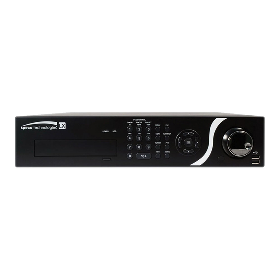
Digital Video Recorder Chapter 3 — Configuration NOTE: Your DVR should be completely installed before proceeding. Refer to Chapter 2 — Installation. Front Panel Controls Figure 3 : 16-Channel DVR front panel. Power LED HDD LED Camera Buttons Menu Button Copy Button Esc Button Play/Stop Button... -
Page 16: Menu Button
Operation Instruction In the PTZ mode, pressing the button 1 zooms in the screen and the button 4 zooms out the screen, pressing the button 2 focuses near and button 5 focuses far, and pressing the button 3 moves to the preset and button 6 saves the preset. Menu Button In the Live Monitoring mode and Search mode, pressing the button displays the menu icons to the right edge... -
Page 17: Enter Button
Digital Video Recorder Enter Button (Enter) button selects a highlighted item or completes an entry that you have made during system setup. Jog Dial When in the playback mode, you can play video forward image-by-image by turning the Jog Dial clockwise and backward image-by-image by turning the Jog Dial counterclockwise. -
Page 18: Remote Control Buttons
Operation Instruction Remote Control Buttons ID Button Camera Buttons Sequence Button Login/Logout Button Arrow Buttons Menu Button Playback Buttons Alarm Button Layout Button Zoom Button PTZ Button Enter Button Esc Button PTZ Control Buttons Copy Button Play/Stop Button Figure 4 : Infrared remote control. NOTE: For simplicity, the button descriptions in this manual refer to the front panel buttons. -
Page 19: Arrow Buttons
Digital Video Recorder Arrow Buttons These buttons are used to navigate through menus and GUI. You can also use them to change numbers by highlighting a number in the menu and using the Up and Down arrow buttons to increase or decrease the number’s value. These buttons are also used to control Pan and Tilt when in the PTZ mode. -
Page 20: Ptz Control Buttons
Operation Instruction PTZ Control Buttons While in the PTZ mode, the buttons are used to save Presets and load a Preset View, the buttons are used PRESET ZOOM to Zoom In and Zoom Out, and the buttons are used for Near Focus and Far Focus. FOCUS Copy Button Pressing the... -
Page 21: Setup Screen
Digital Video Recorder Setup Screen Figure 7 : Setup screen. System Record Event Network Device Display Status Camera Press the button or move the mouse pointer on the right edge of the screen and then select (Setup) in the MENU Live Monitoring menu to enter the setup screen. -
Page 22: Figure 8 : System - General Setup Screen
Operation Instruction Figure 8 : System – General setup screen. In the General screen, you can name the site location, assign a System ID number, select the language the screens are displayed in, display software version number, upgrade the software, show the System Log, display recorded time data, and clear all data. - Page 23 Digital Video Recorder You can import saved DVR settings or export the current DVR settings. To import saved DVR settings, connect the USB device containing the setup file (.dat) to the DVR. Highlight Setup – Import… and press the button. Select the desired setup file and press the Import button to import the selected settings and change the DVR settings accordingly.
- Page 24 Operation Instruction After selecting Shutdown and pressing the button, a screen will appear telling you when it is safe to disconnect power. Highlight EZ Setup and press the button. The EZ Setup screen appears and guides you through configuring the system for basic operation.
- Page 25 Digital Video Recorder Date/Time Setup Date: Set the system date and select the date format. Time: Set the system time and select the time format. Time Zone: Select your time zone. Use Daylight Saving Time: Selecting the box sets the system to use daylight saving time. NOTE: The Date/Time will be set, and the clock will start when you click the Next button.
- Page 26 Operation Instruction Record Video Quality Setup Select the desired video quality profile from: – Higher Video Quality Priority Profile – Standard Recording Profile – Longer Recording Time Priority Profile NOTE: The higher quality setting requires more storage space. The recording resolution will be set to Very High when selecting High Video Quality Priority Profile, High when selecting Standard Recording Profile, and Standard when selecting Longer Recording Time Priority Profile.
- Page 27 Digital Video Recorder If you selected the Go to EZ Network, select the Next button to start the EZ Network. Internet Connection Select whether or not your DVR is connected to the Internet. LAN Setup Select between Auto Configuration and Manual Configuration for network configuration, and then select the Test button to test the network configuration you selected.
- Page 28 Operation Instruction NOTE: Selecting Auto Configuration allows the DVR to automatically obtain LAN parameters (IP address, Gateway, Subnet Mask and DNS Server address). Selecting Manual Configuration allows you to set up LAN parameters manually. The network configuration you set should be tested by selecting Test, otherwise the Next button will cannot be selected, and you cannot move to the next step.
-
Page 29: Date/Time
Digital Video Recorder Date/Time Highlight Date/Time and press the button, and the Date/Time setup screen appears. Figure 9 : System – Date/Time setup screen. Highlight the first box beside Date and press the button. The individual sections of the date will highlight. Use the Up and Down arrow buttons to change the number. -
Page 30: User
Operation Instruction Highlight the box beside Time Server and press the button. A virtual keyboard appears that you can use to enter the IP address or domain name of the time server. Highlighting allows you to select your time server from a list of registered time servers. - Page 31 PC running Speco Central. System Time Change – The user can change the system date and time on a local system or a PC running Speco Central. Data Clear – The user can clear all video data or format disks on a local system or a PC running Speco Central.
-
Page 32: Storage
Operation Instruction Highlighting the box beside Auto Logout allows you to select from a list of times that the user will be automatically logged out. The options are: Never, 1 min., 3 min., 5 min., 10 min., 15 min., 20 min., 30 min. and 1 hr. Storage Highlight Storage and press the button. -
Page 33: Monitoring
Digital Video Recorder CAUTION: Do NOT disconnect the USB cable or the power from the device while copying video clips. If the USB cable is disconnected while copying video clips, archived data might be lost. Highlight the boxes beside Mirror and press the button. -
Page 34: Capacity Estimator
NOTE: Alarm-Out action cannot be set to System , Boot Up, Restart and Shutdown events. For the Notify action to work, the DVR should be registered in the Speco Central (Remote Administration System). Capacity Estimator Highlight Capacity Estimator and press the button, and the Capacity Estimator setup screen appears. -
Page 35: Recording Setup
Digital Video Recorder Recording Setup General Highlight General and press the button, and the General setup screen appears. Figure 14 : Record – General setup screen. Highlighting Recycle and pressing the button toggles between On and Off. In the Recycle mode, the DVR records over the oldest video data once all available storage space has been used. -
Page 36: Schedule
Operation Instruction CAUTION: When more than one disk is installed in the unit, the DVR records video on the disks sequentially based on time. And these sequentially recorded videos have the advantage that you can search recorded video easily even though a disk is removed from the unit. However, video recorded in the same time range might be saved on different disks by channel and by the type of recording mode. -
Page 37: Figure 16 : Schedule - Settings (Advanced Mode) Setup Screen
Digital Video Recorder Highlight the box under the Day heading and press the button to change the days that the scheduled recording will take place. Choose from: Sun, Mon, Tue, Wed, Thu, Fri, Sat, M~F, Hol and All. Highlight the box under the Range heading and press the button to change the time range that the scheduled recording will take place. -
Page 38: Pre-Event
Operation Instruction NOTE: When multiple events are detected at the same time from a specific channel, the DVR will record event video with the high setting values if the ips, Quality, Resolution and Dwell values of events are different from each other. However, the ips will be reset to the supported maximum value when the ips, Quality, Resolution and Dwell are all set to the highest value. -
Page 39: Archive
Digital Video Recorder When the DVR is in the Event Record mode it is possible to have it record images before the event occurs. The Pre-Event screen allows you to define how to handle pre-event recording. You can turn individual cameras On or Off for pre-event recording. The image speed can be set from 1.00 to 30.00 ips (25.00 ips PAL), image quality can be selectable from Very High, High, Standard and Basic, and image resolution can be selectable from Very High (4CIF/960H), High (2CIF/H960H) and Standard (CIF/Q960H). -
Page 40: Event Setup
Operation Instruction NOTE: The archiving speed might be slower than the recording speed when a large quantity of recorded data is being archived. In this case, the oldest data can be overwritten by the latest data being recorded. To prevent data you want to keep from being overwritten, use the Summary Archive function, or set the recorded image quality to Standard during the archiving process. -
Page 41: Alarm-In
Digital Video Recorder Select — Activates highlighted blocks to detect motion. Clear — Deactivates highlighted blocks so that they will not detect motion. Reverse — Activates inactive highlighted blocks and deactivates active highlighted blocks. Select All — Activates all blocks to detect motion. Clear All —... -
Page 42: Video Loss
Operation Instruction The alarm terminal strip on the back of the DVR has inputs associated with each alarm. You can set up each input on the Alarm-In screen. You can turn each input On or Off by highlighting the alarm number and pressing the button. -
Page 43: Video Blind
Digital Video Recorder Video Blind Highlight Video Blind and press the button, and the Video Blind setup screen appears. The DVR checks to see if anything is blinding a camera. (Local Cameras Only) Figure 22 : Event – Video Blind setup screen. You can turn individual cameras On or Off for video blind detection by highlighting the camera number and pressing the button. -
Page 44: Figure 23 : Event - Text-In Setup Screen
Operation Instruction Figure 23 : Event – Text-In setup screen. The DVR can be set to react to text input from devices such as ATMs (Automated Teller Machines) and POS (Point of Sale; i.e., cash registers). This screen allows you to configure the DVR for each text-in device. Highlight the box under the Setup heading, and press the button. -
Page 45: Network
Digital Video Recorder Highlight the box beside Transaction Start, and press the button. Use the virtual keyboard to enter the Transaction Start string. Refer to the device manufacturer’s documentation for the text string that the device first sends when a transaction starts. -
Page 46: Network Setup
Selecting Select From Speco Central will send audio of the channel selected from Speco Central. NOTE: Depending on network conditions, audio might be interrupted or out of synchronization during transmission. - Page 47 Highlight the box beside Speco Remote – Port and press the button. Set the port number used when accessing Speco Remote by using the Up and Down arrow buttons to increase or decrease the numbers. Highlight Use VNC (Virtual Network Computing) and press the button to toggle between On and Off.
-
Page 48: Ip Address
Highlight the Port Number Setup… box and press the button. The Port Number Setup screen appears. NOTE: You will need to get the appropriate Port Numbers for each Speco Central and Speco Remote related program (Admin, Callback, Watch and Search) from your network administrator. - Page 49 Digital Video Recorder Highlight Use UPnP and press the button to toggle between On and Off. When it is On, port forwarding from the NAT (Network Address Translation) device to the DVR will be enabled automatically via UPnP (Universal Plug and Play) service.
-
Page 50: Dvrns
Operation Instruction DVRNS Highlight DVRNS and press the button, and the DVRNS setup screen displays. Figure 28 : Network – DVRNS setup screen. Highlight Use DVRNS and press the button to toggle between On and Off. NOTE: DVRNS is the technology that automatically sets up your DVR to work seamlessly for remote viewing via your network internet connection. -
Page 51: Rtsp
On and Off. When set to on, you can access a remote DVR using a Blackberry or other mobile devices. NOTE: Selecting Use Mobile sets the Speco Remote service to be enabled automatically regardless of Speco Remote settings. -
Page 52: Notification
The DVR will send an email containing a summary of events detected during the preset interval. Highlight Callback – Setup and press the button, and the Callback screen appears. The DVR can be set up to contact a computer running Speco Central (Remote Administration System) when an event occurs. - Page 53 Digital Video Recorder Highlight the box under the No. heading and press the button to toggle between On and Off. You will only be able to change the IP addresses if No. is enabled. Highlight the IP Address box that you want to change and press the button.
-
Page 54: Device Setup
Operation Instruction Highlight the box beside Authentication and press the button. An Authentication screen appears. Highlight Use and press the button to toggle between On and Off. Highlight the box beside User/Password and press the button. A virtual keyboard appears allowing you to enter the user ID and password. NOTE: This product includes software developed by the OpenSSL Project for use in the OpenSSL Toolkit (http://www.openssl.org/). -
Page 55: Network Audio
Digital Video Recorder Figure 31 : Device – Local Audio setup screen. The DVR can record up to four audio inputs. Highlight the box beside the input and press the button. A list of local cameras appears, and you can select which camera you want associated with that audio input. Network Audio Highlight Network Audio and press the button, and the Network Audio setup screen appears. -
Page 56: Digital Deterrent
Operation Instruction Digital Deterrent Highlight Digital Deterrent and press the button. The Digital Deterrent setup screen allows you to set up the DVR to sound when events are detected. Figure 33 : Device – Digital Deterrent setup screen. Highlight the + and press the button to add a digital deterrent schedule item. - Page 57 Digital Video Recorder NOTE: File format has to be mono G.711 ulaw 16KHz/16bit sampling. The file names have to be "Sound_1.wav" ~ "Sound_16.wav" or "Sound_1.aaf" ~ "Sound_16.aaf" for USB import. (USB has to be in FAT32) The files have to be in the top folder of the USB flash drive. The file name format is case insensitive.
-
Page 58: Alarm-Out
Operation Instruction Alarm-Out Highlight Alarm-Out and press the button. The Alarm-Out screen allows you to change the settings and establish a schedule for each alarm output from the DVR. Figure 34 : Device – Alarm-Out setup screen. Highlighting the box beside Dwell Time and pressing the button allows you to set the dwell time of the alarm output. -
Page 59: Remote Control
Digital Video Recorder Remote Control Highlight Remote Control and press the button. The Remote Control setup screen allows you to select a port and make correct settings for a remote keyboard. Figure 35 : Device – Remote Control setup screen. Highlight the box beside Port and select from None, RS232 and RS485. -
Page 60: Primary Monitor
Ethernet. The icon displays on each camera when audio communication is available between the DVR and a PC running Speco Central via Ethernet. The icon displays when VNC service is running. -
Page 61: Spot Monitor
Digital Video Recorder NOTE: Any cameras that are Off, have lost video or are set to Covert (unless the user has authority to view covert cameras) will be excluded from the Cameo sequence. You can define the screen layout in a variety of formats and set the DVR to sequence through the different screen layouts (pages) so that all the cameras will be displayed. -
Page 62: Status Setup
Operation Instruction You can define which cameras display sequentially on the Spot Monitor when in the single-screen display format. Highlighting the box under the Camera and pressing the button toggles between On and Off. You can adjust the display dwell time by highlighting the box under the Dwell and pressing the button. -
Page 63: Storage
Digital Video Recorder Disk Added/Removed will be highlighted when the hard disk drive is connected or disconnected while the DVR is operating. No storage found will be highlighted when there is no storage device for recording is installed in the DVR when the DVR boots for the first time. -
Page 64: Ptz
Operation Instruction Figure 41 : Camera – General setup screen. You can turn the camera number On or Off, and you can change the Title of each camera using the virtual keyboard. You can also determine which cameras will display on the monitors by selecting Normal, Covert 1 or Covert 2 from a drop-down list in the Use column. -
Page 65: Network Camera
Digital Video Recorder Highlight the box in the Product column for the PTZ camera you wish to configure and press the button. A list of PTZ devices appears. Select your camera from the list and press the button. You will need to connect the camera to the RS232 or RS485 connector on the back of the DVR following the camera manufacturer’s instructions. - Page 66 Operation Instruction Highlighting the box beside Protocol and pressing the button allows you to select the protocol for the network device you want to search. NOTE: Refer to the network device manufacturer’s instructions about enabling the ONVIF Conformance protocol in the device, as procedures may differ for each model. Highlight the box beside Mode, and press the button.
- Page 67 Digital Video Recorder Highlight Device Register and press the button to register the selected network device(s) from the list. An Authentication screen appears. Setting up the Authentication is required to register the network device to the DVR. Highlight the box beside User/Password and press the button.
- Page 68 Operation Instruction NOTE: When the device’s settings have been changed using the tool provided by the device manufacturer, you might need to register the device to the DVR again for proper operation. Refer to the device manufacturer’s instructions for proper settings.
-
Page 69: Chapter 4 - Operation
Digital Video Recorder Chapter 4 — Operation NOTE: This chapter assumes your DVR has been installed and configured. If it has not, please refer to Chapters 2 and 3. The DVR’s controls are similar to a VCR. As with a VCR, the main functions are recording and playing back video. However, you have much greater control over recording and playing back video. -
Page 70: Live Monitoring Menu
Operation Instruction Live Monitoring Menu Login/Logout Selecting (Login) in the Live Monitoring menu accesses the Login screen, and you will be asked to select a User and enter the password to log into the system. Selecting (Logout) in the Live Monitoring menu displays the Logout screen asking you to confirm whether or not you want to log out the current user. - Page 71 Digital Video Recorder Highlight the box beside Source name and press the button to select the source file to play. Highlighting Trigger plays the selected file as the digital deterrent. Panic Selecting (Panic) in the Live Monitoring menu starts panic recording of all cameras, and selecting again stops panic recording.
-
Page 72: Active Cameo Mode
Operation Instruction Setup (Setup) in the Live Monitoring menu enters the Main Setup screen. Refer to Chapter 3 ─ Configuration Selecting for detailed descriptions of system setup. Active Cameo Mode You can enter the Active Cameo mode by selecting Edit Group from the Live Monitoring – Display menu or pressing button on the front panel in any multi-view format. -
Page 73: Event Monitoring
Digital Video Recorder You can save camera position settings as “presets” so that you can go directly to desired views. Once you have the camera at the desired settings, press the camera button 6, and the Set Preset dialog box will appear. Select the number you want to assign to the preset and press the button. -
Page 74: Covert Camera
Operation Instruction Covert Camera If a camera is set up as Covert 1 in the Camera setup screen (General tab), that camera will not be displayed unless a user with Covert Camera View authority logs into the system. However the camera title and status icons will be displayed on the monitor. -
Page 75: Panic Recording
Digital Video Recorder Panic Recording Selecting (Panic) in the Live Monitoring menu or Search menu starts panic recording of all cameras. Selecting again stops panic recording. If you set the Panic Recording Duration in the Panic Record setup screen, panic recording will stop automatically according to the preset duration as long as is not selected. -
Page 76: Searching Video
Operation Instruction Jog Dial, Shuttle Ring Jog Dial: The Jog Dial only functions when playback video has been paused. By turning the jog dial clockwise, you can play video forward image-by-image. By turning the jog dial counterclockwise, you play video backward image-by-image. -
Page 77: Search Menu
Digital Video Recorder Search Menu Search Event Log Search: Selecting (Search) → Event Log Search selects video from the event log. See the following Event Log Search section for details. Record Table Search: Selecting (Search) → Record Table Search selects using a recording table. See the following Record Table Search section for details. - Page 78 Operation Instruction Digital Deterrent Selecting (Digital Deterrent) in the Search menu displays the following setup screen and allows the DVR to play manually. Highlight the box beside Source name and press the button to select the source file to play. Highlighting Trigger plays the selected file as the digital deterrent.
-
Page 79: Event Log Search
Digital Video Recorder Event Log Search Figure 49 : Event Log Search screen. The DVR maintains a log of each time the Alarm Input port is activated. The Event Log Search screen displays this list. Use the arrow buttons to highlight the event for which you would like to see video. The Event Log Search screen can also be accessed by pressing the button unless there is an alarm. - Page 80 Operation Instruction Highlight the box beside Check Time Overlap and press the button. It toggles between On and Off. You will only be able to turn the Check Time Overlap on or off if a user-defined date and time is set to From and To. If the DVR’s date and time have been reset, it is possible for the DVR to have more than one overlapping start and stop time.
-
Page 81: Record Table Search
Digital Video Recorder Record Table Search < Compact View > < Standard View > < Expanded View > Figure 50 : Record Table Search screen. Recording information about video images currently displayed on the screen displays on the recording status bar. A grey vertical line indicates the current search position. -
Page 82: Motion Search
Operation Instruction NOTE: If the DVR has images recorded in more than one recording mode in the same time range, the recording status bar displays recording information in the following priority order: Panic → Pre-Event → Event → Time → Irregular (Irregular recording caused by temporary disconnection from the network device). The color of the bar indicates different recording modes: Red for Panic, Yellow for Pre-Event, Purple for Event, and Blue for Time. - Page 83 Digital Video Recorder The Motion Search… can be selected from the Search menu while the DVR displays the camera full screen. The Motion Search screen displays a list of motion events. Use the arrow buttons to highlight the event for which you would like to see video and press the button to display the video associated with the selected event on the small search screen.
-
Page 84: Text-In Search
Operation Instruction Text-In Search Figure 52 : Text-In Search screen. The DVR maintains a log of each time there is Text Input. The Text-In Search screen displays this list. Use the arrow buttons to highlight the event for which you would like to see video. Pressing the button will extract the video associated with the Text Input and display the first image of the event. -
Page 85: Ez Search
Digital Video Recorder Highlight the Text Input Device box and press the button. Select your Text Input Device from the list. Highlighting the + and pressing the button allows you to add a new set of search parameter. Set up the desired search parameter. -
Page 86: Bookmarks
Operation Instruction Bookmarks The Bookmarks screen can also be accessed by selecting Bookmark in the Search – Go To menu. Highlight the Add Current Position box and press the button to add the current playback point to the bookmark list. Highlight the Title box and enter the name of the registered bookmark. - Page 87 Digital Video Recorder Highlight the box beside From and press the button to toggle between On and Off. When set to Off, you can enter a specific Date and Time. When set to On, the search will be from the first recorded image. When highlighting pressing the button the bookmark list displays and the bookmark point you selected will be the starting date and time.
-
Page 88: Print
Operation Instruction You do not need to install any special software on your personal computer to review the video clips. Refer to Speco Central Operation Instruction for instructions on how to review video clips you have copied. NOTE: During Clip Copy, you cannot shut the system down, clear data on the storage device, or format the storage device. -
Page 89: Figure 56 : System - Storage Setup Screen
Digital Video Recorder Figure 56 : System – Storage setup screen. You can enable mirroring between two disks by designating the source disk and the destination disk from a list of internal hard disk drives. Up to two Mirrors are supported. Highlighting the boxes under Source and Dest. - Page 90 Operation Instruction...
-
Page 91: Appendix
Digital Video Recorder Appendix USB Hard Disk Drive Preparation NOTE: The following description is for preparing a USB hard disk drive under Windows 2000. Preparing a USB hard disk drive under Windows XP, Window Vista and Window 7 is almost identical to Windows 2000. Connect the USB hard disk drive to your computer using the USB Cable. -
Page 92: Search Example Ii
Operation Instruction Search Example II 123456789012345678901234567890123456789012345678901234567890 Item Unit price amount ================================================== Coke 2.20 | 1(s) 2.20 Fanta 2.20 | 1(s) 2.20 Hotdog 3.50 | 3(s) 10.50 Pepsi 1.95 | 1(s) 1.95 ================================================== total : $ 16.85 Thank you~~ In the above text-in data, you can find that the comparison value is located at 17th (Unit price, $ mark will be ignored automatically), 28 (Qty) and 40 (amount) characters (including spaces) from the left, but the value of amount... -
Page 93: Speco Remote
– DVRNS server) NOTE: You will need to get the appropriate IP address for the DVR you want to connect to and the Speco Remote port number from your network administrator. Speco Remote only works with Microsoft Internet Explorer and will NOT work with other browsers. -
Page 94: Web Monitoring Mode
② Click the to access to the web search mode. ③ Position the mouse pointer on the Remote Watch logo to see the version of the Speco Remote program. ④ The DVR information window displays the login information of Speco Remote. -
Page 95: Web Search Mode
30 minutes. ① Click the to log out the Speco Remote program. ② Click the to access to the web monitoring mode. ③ Position the mouse pointer on the Remote Search logo to see the version of the Speco Remote program.. -
Page 96: Time Overlap
Operation Instruction ④ The DVR information window displays the time information of recorded data on the remote DVR and login information of Speco Remote. ⑤ Click the to blur, sharpen, equalize and interpolate playback images. Click the to zoom out or zoom in the recorded image. Click the to adjust the brightness of the recorded images. -
Page 97: Remote Setup Of Network Devices
Digital Video Recorder If you want to search recorded video from four to five o’clock during the overlapping time range using a search menu such as Event Log Search, Text-In Search or Motion Search, it is possible for the DVR to have two overlapping start and stop times. - Page 98 Operation Instruction System Setup Information: Displays the device information. Maintenance: Restarts the device or returns all device settings to the original factory settings. Security Setup User: Adds or deletes a user. Media Setup ONVIF Profile: Adds or deletes an ONVIF profile.
- Page 99 Digital Video Recorder Network Setup TCP/IP: Sets up the device’s IP address and DNS server. DDNS: Sets up the DDNS function. Zero Configuration: Automatically allocates an appropriate IP address for the current network conditions (supported only for devices that provide the function). ...
-
Page 100: Connector Pin Outs
Operation Instruction PTZ Setup PTZ: Sets up the PTZ. Connector Pin Outs I/O Connector Pin Outs AI (1 to 16) Alarm Inputs 1 to 16 Chassis Ground (5 connectors) Relay Alarm Output (Normally Closed) Relay Common Relay Alarm Output (Normally Open) Alarm Reset In RS485 Connector Pin Outs Master Unit... -
Page 101: Map Of Screens
Digital Video Recorder Map of Screens MENU SYSTEM General Date/Time User Storage Monitoring RECORD General Schedule Pre-Event Archive EVENT Motion Alarm-In Video Loss Video Blind Text-In Network NETWORK General IP Address DVRNS RTSP Notification DEVICE Local Audio Network Audio Digital Deterrent Alarm-out Remote Control DISPLAY... -
Page 102: Error Code Notices
Operation Instruction Error Code Notices System Upgrade Related Clip Copy Related Description Description Unknown error. Unknown error. File version error. Device error. Operating system version error. Mounting failed. Software version error. No media. Kernel version error. Invalid media. Upgrade device mounting failed. File already existed. -
Page 103: System Log Notices
Digital Video Recorder System Log Notices Boot Up Setup Export Failure Clip-Copy Fail Shutdown Setup Export Cancel Clip-Copy User: Restart Schedule On Clip-Copy From: Upgrade Schedule Off Clip-Copy To: Upgrade Fail Panic On Clip-Copy Duration of Video: Power Failure Panic Off Clip-Copy Camera: Time Change Clear All Data... -
Page 104: Specifications
Operation Instruction Specifications VIDEO Signal Format NTSC or PAL (Auto Detect) Local Composite: 8 or 16 looping inputs, 1 Vp-p, auto-terminating, 75 Ohms Video Input Network 4 network devices (100Mbps/1Gbps Ethernet) HDMI: 1 HDMI Monitor Outputs VGA: 1 SPOT: 1 BNC, 1 Vp-p, 75 Ohms HDMI/VGA: 1920x1080p, 1920x1080i, 1280x1024, 1024x768 Video Resolution Composite (SPOT): 704x480 (NTSC), 704x576 (PAL) - Page 105 Digital Video Recorder GENERAL Dimensions (W x H x D) 16.9" x 3.5" x 15.7" (430mm x 88mm x 400mm) Unit Weight 17.9 lbs. (8.1kg) Shipping Weight 24.5 lbs. (11.1kg) Shipping Dimensions 21.3" x 11.4" x 23.2" (540mm x 290mm x 590mm) (W x H x D) Operating Temperature 41°F to 104°F (5°C to 40°C)
Need help?
Do you have a question about the D12LX and is the answer not in the manual?
Questions and answers