
Related Manuals for Microcom 424


Summary of Contents for Microcom 424
- Page 1 MODEL 224 / 424 DIRECT THERMAL PRINTER OPERATOR’S MANUAL PART NUMBER 880027-1000 Revised: December 6, 2007 JSR, TER Copyright © 2005 by Microcom Corporation, Lewis Center, Ohio – All rights reserved.
- Page 3 For this reason, specifications are subject to change without notice. Liability Disclaimer Microcom Corporation makes every effort to assure that all information and specifications contained in this manual are accurate; however, mistakes are sometimes made. Microcom Corporation shall not be liable for any damages resulting in the use or misuse of this product.
-
Page 5: Table Of Contents
CHAPTER 4: DESIGNING LABELS USING LDS ........4-1 Control Characters ....................4-1 LDS Design Exercises ..................4-1 4.2.1 PC Connection (Serial) ................. 4-1 4.2.2 Format Creation .................... 4-2 Label Design: An Overview.................. 4-3 Label Header ....................... 4-4 224/424 Operator’s Manual - 880027-1000... - Page 6 Software Switch #1 ................5-5 5.2.2.2 Software Switch #2 ................5-6 5.2.2.3 Software Switch #3 ................5-7 5.2.2.4 Software Switch #4 ................5-8 5.2.2.5 Software Switch #5 ................5-9 5.2.2.6 Software Switch #6 ................5-10 224/424 Operator’s Manual - 880027-1000...
- Page 7 Compressed Binary GRAPHIC Downloads ..........6-3 Advanced GRAPHIC Format Conversion for Programmers......... 6-3 6.5.1 Save Compressed Graphics to RAM (D107) ..........6-4 6.5.2 Save Compressed Graphics to FLASH (D133)..........6-4 6.5.3 Binary Compression Algorithm ..............6-5 224/424 Operator’s Manual - 880027-1000...
- Page 8 8.1.22 RSS-14, TCI 35................... 8-16 8.1.22.1 RSS-14 Standard ................. 8-16 8.1.22.2 RSS-14 Truncated ................8-17 8.1.22.3 RSS-14 Stacked .................. 8-17 8.1.22.4 RSS-14 Stacked Omni-directional ............8-17 8.1.22.5 RSS-14 Limited..................8-18 8.1.22.6 RSS-14 Expanded ................8-18 224/424 Operator’s Manual - 880027-1000...
- Page 9 Appendix B: ^D Command Summary............... 12-2 Appendix C: Glossary .................... 12-17 Appendix D: User Notes..................12-21 INDEX ......................13-1 General Index ......................13-1 List of Figures ......................13-7 List of Tables ......................13-9 INTRODUCTION .................... VII 224/424 Operator’s Manual - 880027-1000...
- Page 10 224/424 Operator’s Manual - 880027-1000...
- Page 11 This manual covers both the 224 and 424 printers. The primary difference in the two printers is print width. The 224 uses a 2.1 inch (53mm) print head and the 424 uses a 4.1 inch (104mm) print head. Both printers are offered with a standard resolution of either 203 dpi (8 dots/mm) or an optional 300 dpi (12 dots/mm).
- Page 12 224/424 Operator’s Manual - 880027-1000...
-
Page 13: General Specifications
300 DPI (12 dots/mm = 0.0032” per dot) Maximum Print Speed 8”/sec. (203 mm/sec.) 224 - 203DPI = 2.1” (53 mm) Maximum Print Width 424 - 203DPI = 4.098” (104 mm) Maximum Print Length 50” (1,270 mm) with 203 dpi Table 1-2 Printing Specifications... -
Page 14: Media Specifications
**NOTE: The 224 printer’s media path has a maximum width of 2.5” while the actual printable width is 2.1” for the 203 DPI print head. ***NOTE: The 424 printer’s media path has a maximum width of 4.5” while the actual printable width is 4.095” for the 203 DPI print head. -
Page 15: Fonts
• Storage of fonts, label formats and graphics in both volatile RAM and non- volatile FLASH memory. • All BMP files may be converted using a Microcom utility program. • Rotated: 0 º, 90 º, 180 º, and 270 º. -
Page 16: Special Features
• Cutter – Full and partial • Label Present Detector (LPD) reflective sensor with indicator light and adjustable range • 10/100BASE-T Ethernet communications port • Catch Tray • External label roll rack (8” O.D. max) • Cleaning kit 224/424 Operator’s Manual - 880027-1000... -
Page 17: Typical Printer Accessories
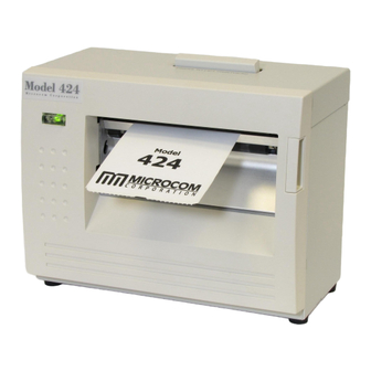
After the printer is removed from the container(s), verify that all the items on the packing list are present and in good condition. The picture below (See Figure 3-1) shows a 424 printer, operator's manual, and optional power cord. Your shipment may contain different items. -
Page 18: Ac Power Connection
3.2.1 Printer Power The 224/424 printer has a universal auto-sensing internal power supply that operates in the 100-240 VAC; 50-60 Hertz range. The three-prong female end of the power cord plugs into the mating connector located on the back of the printer. -
Page 19: Cable Configurations
The printer uses a standard through serial cable, typically referred to as a modem cable, which may be purchased through Microcom Corporation or a local computer supply company. A NULL-modem cable is not required because the printer is configured as DCE. -
Page 20: Usb Communication Interface
^D115 command and will be reported on the Statistics Label. 3.3 Loading Media The easy- to-release print head makes loading media into the Model 224/424 printer an easy process. Follow the instructions below to properly load the media. -
Page 21: Print Button And Status Indicator Light
The Print Button and the Status Indicator Light are used to identify and perform many functions. This section provides a description to familiarize you with the basic function of the Print Button and the Status Indicator Light. 224/424 Operator’s Manual - 880027-1000... -
Page 22: Print Button Description
Press & hold the Print Button while the printer is IDLE to advance Feeding labels label media. The printer will continue advancing label media until (Line feed) the Print Button is released. Table 3-2 Print Button Description 224/424 Operator’s Manual - 880027-1000... -
Page 23: Status Indicator Light Description
If the printer was just turned ON and no formats were sent to the printer, pressing quickly will print the power-up label, c) Holding the button depressed: Form Feed labels until the button is released. 224/424 Operator’s Manual - 880027-1000... -
Page 24: Halted Mode: Red
The printer will use the factory default parameters until the printer has been reset using a soft reset or by cycling power. The printer will then return to the configuration shown on the Status Label. 224/424 Operator’s Manual - 880027-1000... -
Page 25: Status Label (Examples)
STOCK OUT VALUE: 100 STOCK OUT VALUE: 100 PRINTER CODE REV: 02.12.050719A PRINTER CODE REV: 02.12.050719A BOOTLOADER CODE REV: 02.12.050719A BOOTLOADER CODE REV: 02.12.050719A CODE ASSY PN. 071001-0212 CODE ASSY PN. 071001-0212 Figure 3-6 Status Label (Examples) 224/424 Operator’s Manual - 880027-1000... - Page 26 Getting Started Chapter 3 3-10 224/424 Operator’s Manual - 880027-1000...
-
Page 27: Control Characters
COM1:9600,n,8,1,p) command before copying the files to the port. Create a text file, enter “^D3” <CR> (carriage return) and save it as “D3.txt”. Send the file to the printer by either using the DOS COPY (C:\>copy d3.txt com1) command or by using a terminal program. 224/424 Operator’s Manual - 880027-1000... -
Page 28: Hyperterminal™ Window Example
The LDS programming language uses thermal dots as the unit of measure. All commands and parameters, unless noted otherwise, should be entered using dots. The 224 and 424 printers may be fitted with either a standard density 203dpi head, or a higher density 300dpi print head. -
Page 29: Label Design: An Overview
Below is a sample label format created for the Model 424 with a 300 DPI print head. We will refer to this format as we break down the steps and components to produce the format. -
Page 30: 3X3 Sample Label
Dot or pixel size varies depending upon the print resolution of the print head. Two print resolutions are currently available for the 224 and 424 printers (203 DPI and 300 DPI). The dot size of a 203 dots per inch head (8 dots/mm) is 0.0049”. The dot size of a 300 dots per inch head (12 dots/mm) is 0.0032”. -
Page 31: Header Elements
Thermal Printing Solutions 3.0” or 900 Dots 012345 X beginning This is the Gap Value origin; 1,1 .125” or 40 Dots Y beginning 4.266” or 1280 Dots (Total Print Head Dots) Figure 4-3 Header Elements 224/424 Operator’s Manual - 880027-1000... -
Page 32: Valid Lsx Values
The DPS parameter is used to set the printing speed for the printer. Refer to Table 4-2 for the list of print speeds, DPS values, and corresponding inches per second values. To print at greater speeds, change the DPS value to a lower setting as shown on Table 4-2. 224/424 Operator’s Manual - 880027-1000... -
Page 33: Dps Values
This parameter selects the method the printer uses for detecting registration marks on the different media types. The Model 224 and 424 printers have both upper (transmissive) and lower (reflective) gap detectors as standard equipment. The following sections discuss the LCB settings for the different media types. -
Page 34: Continuous Media (Setting = 2)
HFM, LSX, LSY, WEB, GAP, DPS, LCB, AGD, , OFX, OFY This parameter is used to specify the number of steps (thermal dots) to advance the media after a registration mark has been detected. This parameter is required to properly register 224/424 Operator’s Manual - 880027-1000... -
Page 35: Dot To Gap Parameters
GAP header parameter. Calculation Examples: Die-cut Media: A 424 203 DPI printer being used with 3" x 1" media containing a .125" die-cut gap. The SPG would be calculated as follows: SPG = (D2G + LSY - DRM) mod (LSY + SBL) -
Page 36: Ofx (Offset X Direction)
(“,”). A carriage return must follow each format field for proper operation to occur. The values entered must be positive integers for all of the parameters of the format field. 4-10 224/424 Operator’s Manual - 880027-1000... -
Page 37: Label Format Field Elements
A TSN of “2” accesses the second line of data, and so forth. The text data is the text that follows the “^D2<CR>” command in the label’s layout. A graphic image field must point to a text string that contains at least one character. The maximum value for a TSN is 65536. 224/424 Operator’s Manual - 880027-1000 4-11... -
Page 38: Xb (X Beginning Coordinate)
All of the TCI values used by the 224/424 printer are listed in Table 4-4 below. For example, a TCI of “1” for the text string data “012345” would print the text “012345” while a TCI of “15” would produce an “Interleaved 2 of 5 symbol”. -
Page 39: Tci Values
The CGN parameter is a numeric entry that determines the representation and size of embedded font and bar codes as well as the memory location of graphic images that have been selected by the TCI parameter. 224/424 Operator’s Manual - 880027-1000 4-13... -
Page 40: Cgn-Embedded Fonts
Designing Labels Using LDS Chapter 4 4.6.6.1 Embedded Fonts The Model 224 and 424 printers provide seven resident Helvetica style embedded fonts that can be selected using the CGN when text is selected by the appropriate TCI value. Embedded Bitmapped Fonts POINT... -
Page 41: Cgn - Standard Downloadable Font Set
See Chapter 8 for more detailed information on designing label formats using bar code symbols. Some bar codes do not require a CGN value and should be omitted by entering the comma delimiter. 224/424 Operator’s Manual - 880027-1000 4-15... -
Page 42: Cgn-Bar Code Symbologies
This parameter defines the justification of the format field on the label. Left Justified above the base-line Right Justified above the base-line Left Justified below the base-line Right Justified below the base-line Centered above the base-line Centered below the base-line 4-16 224/424 Operator’s Manual - 880027-1000... -
Page 43: Fo & Fj Character Starting Positions
Multiplying a text string will not multiply the spacing between characters. This element may be used to properly space the characters to create the desired printed effect. 224/424 Operator’s Manual - 880027-1000 4-17... -
Page 44: Tsp (Text Starting Position)
(commas) without values. An example of two lines drawn on a label is shown in Figure 4-5. This 3 x 3” label was designed for a 424 printer with a 300 DPI print head. ^D57 <CR>... -
Page 45: Label Format Line Draw
“Line” was used in the example to clearly define the label format fields that contain line values. However, it could have simply been one character such as a period “.” XB (X Beginning Coordinate) The X and Y coordinates determine the start of the line draw. 224/424 Operator’s Manual - 880027-1000 4-19... - Page 46 Format Fields defining the line draw and the text fields. The size of the box is not defined by the text. Adjustment to the size of the box must be made by adjusting the line draw coordinates. 4-20 224/424 Operator’s Manual - 880027-1000...
-
Page 47: Reverse Video Sample
It is possible to create a reverse video effect with barcodes using this method. ^D57 5,1280,900,0,0,7,2,0,1,0,0 1,640,700,8,1,5,0,4,2,2,,,,,8 2,640,591,11,1,5,0,4,2,2,,,,,8 3,640,465,26,1,3,0,4,2,2,,,,,8 4,640,350,6,1,3,0,4,2,2,,,,,8 4,640,50,6,16,3,,4,5,150,,,,,1 ^D56 Microcom Corporation Thermal Printing Solutions 012345 Figure 4-8 Auto Reverse Video Sample 224/424 Operator’s Manual - 880027-1000 4-21... - Page 48 Designing Labels Using LDS Chapter 4 4-22 224/424 Operator’s Manual - 880027-1000...
-
Page 49: Chapter 5 Printer Commands
Chapter 5 Printer Commands The 224 and 424 printers have a large and versatile collection of control commands to meet the special needs of labeling applications. Most of the commands use the “^D” control sequence, however the printer also recognizes a selected number of other control sequences. - Page 50 ^E is that when printers are configured for binary compression (D23 -SW3 bit 7), which is required if saving graphics, the ^E will not function. This means that if the printer is going to be 224/424 Operator’s Manual - 880027-1000...
-
Page 51: Enquiry Responses
Byte Mode: The response is sent to the host as a hexadecimal number (byte) as shown in Table 5-1. Each string is represented by a single byte with nothing separating them. The end of the response is terminated with a FFh character. 224/424 Operator’s Manual - 880027-1000... -
Page 52: Basic Printer Configuration Commands
115,200 when the printer is in the Diagnostic Mode if the user setting is different. The user set baud rate will resume after a “soft reset” (^D32) or cycling the power to the printer. 224/424 Operator’s Manual - 880027-1000... -
Page 53: Software Switches
1 = Ignore Incoming Control Codes 0 = Accept Incoming Control Codes Port #1 Parity Selection: Sets the printer port #1 parity for serial communication. 1 = Odd Parity 0 = Even Parity 224/424 Operator’s Manual - 880027-1000... -
Page 54: Software Switch #2
Print Button: Defines the function of the Print Button. If set to a “0”, the button can be used for feeding labels but the print function is disabled. 1 = Label FEED & PRINT 0 = Label FEED only 224/424 Operator’s Manual - 880027-1000... -
Page 55: Software Switch #3
>INPUT 2< response. 1 = Send >INPUT 2< for NO reflection (green LED is OFF) 0 = Send >INPUT 2< for reflection (green LED is ON) 224/424 Operator’s Manual - 880027-1000... -
Page 56: Software Switch #4
1 = Enable 0 = Disable Paper Out function: Enable this function to get a >LOW STOCK< message when the printer runs out of paper. 1 = Disable 0 = Enable (PAPER-OUT detection gives >LOW STOCK<) 224/424 Operator’s Manual - 880027-1000... -
Page 57: Software Switch #5
This is typically used on systems that preload a batch of jobs to the printer but wait on the >BUTTON PRESSED< message before sending the print command. 1 = Enable >BUTTON PRESSED< 0 = Disable 224/424 Operator’s Manual - 880027-1000... -
Page 58: Software Switch #6
>TRAY FULL< error when used with the optional catch tray. This bit will determine the printer's response when pin 4 of P17 is active. 1 = >TRAY FULL< condition. 0 = A test pattern is printed. Always 0 Always 0 5-10 224/424 Operator’s Manual - 880027-1000... -
Page 59: Emulation Fonts
Model 48-466 Operators Manual for additional information regarding the command operation. a) The printer supports the CGN lookup as defined above and in the 48-466 Operators manual when the emulation command is enabled. 224/424 Operator’s Manual - 880027-1000 5-11... - Page 60 4 additional inputs accessed through the P17 connector on the PCB, report the status of 4 additional outputs accessed through the P21 5-12 224/424 Operator’s Manual - 880027-1000...
- Page 61 F. The outputs equal a binary number with the values in the following order; 4321. Example: A status of >IO 05H< would indicate that outputs 1 and 3 are active (24v) and that outputs 2 and 4 are inactive (0v); 05H = 0101(binary). 224/424 Operator’s Manual - 880027-1000 5-13...
- Page 62 NOTE: Default power up will disable I/O mode. The P17 and P21 connectors are 8 pin MTA50 AMP part number #1445350-8 and Microcom Corporation part number 510188-0008. The pin out is as follows (the square pad denotes pin one on the PCB): Connector P17 is the input port.
- Page 63 Unless the printer is properly configured with a take- up motor and correct take-up motor specific PIC, this mode should not be enabled because it could potentially damage the cutter. Always 0 224/424 Operator’s Manual - 880027-1000 5-15...
-
Page 64: Set Communication Port Selection Commands
Printer Commands Chapter 5 5.2.3 Set Communication Port Selection Commands The 224 and 424 printers have 3 different serial communication ports on the rear panel: 1) RS-232D 115,200 bits/sec, max. 2) USB 12Mbits/sec 3) Ethernet (option) 10Mbits/sec or 100Mbits/sec Only one of the 3 serial ports can be active at any time, but all 3 cables can be connected to the printer at the same time. -
Page 65: Adjust Contrast Window (Volatile - ^D35)
Auto Set Threshold: This command will cause the printer to scroll 1350 dots, determine the proper threshold value, and set the nonvolatile threshold for proper registration. The ^Ax selects either reflective or transmissive detection. Automatically sets the transmissive threshold value. Automatically sets the reflective threshold value. 224/424 Operator’s Manual - 880027-1000 5-17... -
Page 66: Advanced Printer Configuration Commands
5.3.1 Print Head Size Commands The 224 and 424 printers can use a variety of different print head sizes and densities. ^D78 and ^D79 commands (non-volatile) allow the printer to be setup thru software to drive different print head sizes and densities. Power cycle or ^D32 is required before command settings take affect. - Page 67 Function when = “0” 0 (LSB) IN RESET or PRINTING NOT BUSY ERROR NO ERROR DOWNLOADING A FORMAT FINISHED DOWNLOAD FORMAT LOADED NO FORMAT LOADED not used not used not used 7 (MSB) not used 224/424 Operator’s Manual - 880027-1000 5-19...
-
Page 68: Synchronous Print Mode
^D3 is left in the format, an initial label will be printed regardless of the special input line settings. Send the printer a ^D116<CR> command. This will force the printer to process the label to the point that the label bitmap is 5-20 224/424 Operator’s Manual - 880027-1000... -
Page 69: Cutter Configuration Commands
The ^D115 command will assure that the proper type of cutter is reported to the statistics label. It should be used prior to enabling the cutter with the ^D99 command (volatile). Command Set Cutter Type: A non-volatile command to set cutter type. No Cutter Guillotine Rotary 224/424 Operator’s Manual - 880027-1000 5-21... -
Page 70: Kiosk Cutter Advance Distances
This command sets the advance/retract distance for the Kiosk Cutter Mode. The printer has normal “default” values that it uses when it is fitted with a standard Microcom cutter. But in custom applications, the distance between the print head dot row and the cutter blades may be totally different. -
Page 71: Cutter Holdoff
Dispensing commands are commands that advance the media for cutting, tear off, or presenting and then retract the media to a home position so that media is not wasted. These dispense commands include Peel-n-Dispense, Tag/Tear, Cutter commands, and 224/424 Operator’s Manual - 880027-1000 5-23... -
Page 72: Tag/Tear Operation
1. A value of “1” results in a full cut whenever the copies count is reached, or after each format if a copies count has not been specified. If this command is set higher than “1” (maximum of 65536), the printer will full cut 5-24 224/424 Operator’s Manual - 880027-1000... -
Page 73: Load Advance/Retract Distance And Load Advance Delay
Set Starting Slice Number: This command adjusts the number of slices (dot rows) generated before the printer starts moving the label stock. The default is set to 67% of the slice buffer size. Anytime the size of the slice 224/424 Operator’s Manual - 880027-1000 5-25... -
Page 74: Starting Slice Number (Dot Row #)
Because the printer can be fitted with a variety of different head widths and dot densities, the actual number of slices that the buffer can hold will be determined by the number of dots in the print head. 5-26 224/424 Operator’s Manual - 880027-1000... -
Page 75: Slice Buffer Size (Dot Rows)
Slice Buffer Size (dot rows) 5.12 Auto-Load Media The 224 and 424 printers provide an easy way for new media to be loaded into the printer thru the use of the Auto-Load function. When this feature is turned ON, the printer will... -
Page 76: Auto-Load With Top Of Form
Since this is a volatile command the default setting will be restored every time the printer’s power is cycled “OFF” and “ON.” Example: Have the printer wait 1.25 seconds before feeding paper on Auto-Load. ^A1250^D120 5-28 224/424 Operator’s Manual - 880027-1000... -
Page 77: Printing Commands
If the cutter is a rotary cutter, it will always cycle in the forward direction to make a full cut. If the cutter is a guillotine cutter, the cycle direction will be determined by the last setting given with a D99 command. 224/424 Operator’s Manual - 880027-1000 5-29... -
Page 78: Auto-Sizing And Valid Gap Commands
The auto-size command uses the appropriate sensors to detect the registration marks set by the ^D47 command. Before issuing the auto-size command, verify that the ^D47 is set to the proper setting for the media being used. 5-30 224/424 Operator’s Manual - 880027-1000... -
Page 79: Serial Number Commands
Load Increment/Decrement Step Value: The single serial number functions increment or decrement by this value. ^Axx is the amount of increment or decrement. 224/424 Operator’s Manual - 880027-1000 5-31... - Page 80 (^A1^D84), load the step value of 5 (^A5^D85) and then print three serialized labels (^A3^D75). The printed result would be “20” for the first label, “15” for the second label, and “10” for the third or last label. 5-32 224/424 Operator’s Manual - 880027-1000...
-
Page 81: Label Header Parameter Override Commands
Load the Number of Steps to Activate Gap Detector (AGD): The ^Axx specifies the value in Dot Rows. Load the Number of Steps Past Gap (SPG): The ^Axx specifies the value in Dot Rows. Load X Direction Offset (OFX): The ^Axx specifies the value. 224/424 Operator’s Manual - 880027-1000 5-33... -
Page 82: Text String Commands
3,300,300,7,1,5<CR> ^D56 <CR> ^D2 <CR> A<CR> B<CR> C<CR> ^D62<CR> ^D2<CR> line 1<CR> line 2<CR> line 3<CR> ^D3<CR> This format would produce a label with “Aline 1”, “Bline2”, and “Cline 3” printed on the label. 5-34 224/424 Operator’s Manual - 880027-1000... - Page 83 Variable Field<CR> Variable Field<CR> Variable Field<CR> ^A3^D63<CR> (Enables Auto-Print and Clears text) ^A3^D64<CR> (Instructs printer to print after 3 <CR>) ^A4^D61<CR> (Instructs printer to start text entry at line 4 instead of line 1) 224/424 Operator’s Manual - 880027-1000 5-35...
-
Page 84: Memory Commands
Clear User RAM: This command clears all the downloaded fonts and graphics that have been stored in RAM. This command does not affect fonts and graphics that have been downloaded and stored into the FONT flash memory. Use the ^D17 to erase FONT flash memory. 5-36 224/424 Operator’s Manual - 880027-1000... - Page 85 The ^Axx selects the memory slot (1- 128) into which the format is to be saved. A format file must be terminated by an ESC (HEX 1B) or “[“ (left bracket) character to save the format. 224/424 Operator’s Manual - 880027-1000 5-37...
- Page 86 = the number of additional 64KB sectors in the FONT file set yy = CGN # (1-255) If xx = 00, then the FONT fits into one 64Kbyte sector of memory and there are no additional sectors required for the FONT. 5-38 224/424 Operator’s Manual - 880027-1000...
- Page 87 8 data bits, no parity, 1 stop bit. Hint: After the FONT file has been sent, the ^D119 command may be used to verify that the new FONT is now available in FLASH. 224/424 Operator’s Manual - 880027-1000 5-39...
- Page 88 Label FORMATS are saved into FLASH Slots #1 thru #128. Each of these FORMAT slots specifies how to build the dot rows that are used to print a label on the 224 and 424 printers. This command tells the printer to take the Label FORMAT file in Slot #xx and build up its image in the printer’s slice buffer.
-
Page 89: Miscellaneous Commands
IMPORTANT NOTE!!! Embedded FONTS and label FORMATS are NOT erased. However, any custom FONTS and GRAPHICS loaded into user FLASH memory at the factory WILL be erased. Please contact Microcom Corporation if you have any doubts about custom GRAPHICS and/or FONTS that may be stored in FLASH memory. - Page 90 Feeds the media in reverse at the given speed. The ^Ax is the number of dots to move. Dot Feed Speed. Controls the feed speed of the ^D153 and ^D154 commands. The ^Ax is the DPS value 0 through 13. 5-42 224/424 Operator’s Manual - 880027-1000...
-
Page 91: Flash Data Types
Chapter 6: Downloadable Graphics The 224 and 424 printers allow the user to download their own GRAPHICS and store the GRAPHICS in either non-volatile FLASH memory, or in volatile RAM memory. 6.1 FLASH Data Types The printer’s FLASH memory provides non-volatile storage for several types of data: 1) 120 FLASH memory banks are 64Kbyte sectors for storing downloadable FONTS and GRAPHICS. -
Page 92: Bmp2Mic.exe Graphic Conversion Utility Procedure
Press [ENTER] C:\>BMP2MIC.exe 2. Type the conversion utility name and required information at the command prompt. Press [ENTER]. BMP2MIC - Convert BMP Graphic File to Microcom Printer Graphic Rev. 2.01 Copyright 1998-2005 Microcom Corp., Westerville, Ohio Use: BMP2MIC <infile> <outfile> <outtype> <slotnum> <limit> <destination>... -
Page 93: Graphic Download Methods
6.5 Advanced GRAPHIC Format Conversion for Programmers The following sections are provided to developers who wish to create usable GRAPHIC images within their own applications. Commands in the following section are not typically seen for users using Microcom GRAPHIC utilities. 224/424 Operator’s Manual - 880027-1000... -
Page 94: Save Compressed Graphics To Ram (D107)
GRAPHIC uses, not the number of bytes that will actually be transmitted. Due to compression, the number of bytes transmitted will normally be less than this number. <Image Data> is the compressed binary image. 224/424 Operator’s Manual - 880027-1000... -
Page 95: Binary Compression Algorithm
255 copies) totaling 1024 bytes of “FF” HEX. The next “FF” HEX byte adds another and the 6B HEX adds 107 additional copies for a total of 1132 FF HEX bytes. (4 X 256)+1+107 = 1132 224/424 Operator’s Manual - 880027-1000... -
Page 96: Ascii-Hex Conversions
“30” HEX. This results in the two bytes “36” HEX and “3C” HEX. This conversion results in a file size that is twice as big as the source, the data can now be transmitted over a 7-bit data connection. Figure 6-1 ASCII-HEX Conversions 224/424 Operator’s Manual - 880027-1000... -
Page 97: Graphic Image Data Format
Label first_char_data the beginning of the graphic image data Word char_height height of this character’s bitmap in dots 224/424 Operator’s Manual - 880027-1000... -
Page 98: Downloadable Graphics Commands
Deletes the graphics in slot #XX 106* Save GRAPHICs or FONTs into RAM Memory without Compression: This command is intended for legacy support only and Microcom Corporation recommends either the ^D104 or ^D107 commands. Fonts must be less than 64KB for this command to function. -
Page 99: Ram Data Types
Chapter 7: Downloadable Fonts The 224 and 424 printers allow the user to download their own fonts and store the fonts in either volatile RAM memory, or non-volatile FLASH memory. 7.1 FLASH Data Types The printer’s FLASH memory provides non-volatile storage for several types of data: 1) 120 FLASH memory banks are 64Kbyte sectors for storing downloadable FONTS and GRAPHICS, using TCI #7. -
Page 100: Sfp2Mic.exe Program
2. Follow the on screen instructions and note the slot number where the image is saved. The 224 and 424 printers use the same font structure as the Model 412 printer. Select the Model 412 printer when converting fonts for the 224 and 424 printers. -
Page 101: Save Compressed Font To Ram (D127)
This command allows graphic and/or font images (fonts must be less than 64KB uncompressed) to be transmitted in ASCII-HEX, thereby allowing all data to pass over 7 or 8-bit data connections. This command is usable on data connections that support either 7 or 8-bit data. 224/424 Operator’s Manual - 880027-1000... -
Page 102: Save Fonts To Flash (^D135)
00 signals the printer to get ready for a multi-sector FONT download. Each subsequent download contains a header with the xx field decremented by 1. The last download file has a header field xx = 00. 224/424 Operator’s Manual - 880027-1000... -
Page 103: Font Structure
The following font structure is offered to programmers who wish to use their own programs to convert fonts. The font structure consists of a set of data structures and location offsets to those structures. All data is stored in binary form. Multi-byte values are stored “least 224/424 Operator’s Manual - 880027-1000... - Page 104 2d array. The most significant bit of the first byte in each row, prints as the right most dot of the character, and the first row is the bottom row when printed. 224/424 Operator’s Manual - 880027-1000...
-
Page 105: Downloadable Font Command Summary
80 HEX. This command supports GRAPHICS over 64KB. Load GRAPHIC or FONT into RAM Memory without Compression: This command is intended for legacy support only and Microcom Corporation recommends either the ^D104 or ^D107 commands. Fonts must be less than 64KB for this command to function. - Page 106 Downloadable Fonts Chapter 7 224/424 Operator’s Manual - 880027-1000...
-
Page 107: Chapter 8: Bar Codes
UPC-E bar codes do not use inter-character spacing, therefore the character spacing (CS) element must be defaulted. The chart listed in Table 8-1 illustrates how the 11 digits are reduced to only 6 using the “zero suppression” compression. 224/424 Operator’s Manual - 880027-1000... -
Page 108: Upc-E Zero Reduction Format
0 through 9, the English Alphabet (uppercase only), characters -. *$/+% along with the “space” character. The Code 39 is framed with a start/stop character represented by the asterisk (“*”) character, which is reserved for this 224/424 Operator’s Manual - 880027-1000... - Page 109 Postnet is a numeric-only symbology that is commonly used in postal application to sort mail. The five-digit zip or five-digit zip plus four-digit extension may be used to generate this Postnet (TCI 36) bar code. Example: 12345 or 12345-1234. 224/424 Operator’s Manual - 880027-1000...
- Page 110 Mode 2 may have either of the following formats: Format 1 [)>#1e01#dYYPPPPPPPPP#1dCCC#1dSSS#1dA..A#1dB..B#1dC..C#1e#04 Where: #1e is the ASCII RS character #1d id the ASCII GS character #04 is the ASCII EOT character YY is the two digit numeric year 224/424 Operator’s Manual - 880027-1000...
- Page 111 Table 8-2, and occupy only one character in the encoded string. Mode 6 Mode 6 may encode any string up to 93 characters. Control characters are specified in Table 8-2 on the next page, and occupy only one character in the encoded string. 224/424 Operator’s Manual - 880027-1000...
-
Page 112: Maxicode Control Code Equivalents
Control R Control S Control T Control U Control V Control W Control X Control Y Control Z Control [ Control \ Control ] Control ^ Control_ # (pound) Table 8-2 MaxiCode Control Code Equivalents 224/424 Operator’s Manual - 880027-1000... -
Page 113: Code128 Special Function Access
B if no start code is defined. The printer will also not attempt to compress the data unless subset C is used. Once in subset C the user must send the appropriate code (#n) to return to either subset A or B. 224/424 Operator’s Manual - 880027-1000... -
Page 114: Code 128 Subset Switching
128 ASCII character set. The 48 characters include the “space”, numerical characters 0 through 9, the English alphabet (uppercase only), characters $%+-. / along with five special characters including the start/stop character. 224/424 Operator’s Manual - 880027-1000... - Page 115 This parameter controls the rotation of the rendered PDF-417 symbology in 90-degree increments. The valid arguments for this parameter would be 0, 90, 180 or 270 with the default being set to 0. A carriage return character must be used to terminate this field. 224/424 Operator’s Manual - 880027-1000...
-
Page 116: Error Correction Level
(height : width) and has a default value of 1:2. Valid ratios are 2:1, 1:1, 1:2, and 1:3. A carriage return character must be used to terminate this field. Number of Error Correction ECC# Codewords Table 8-4 PDF-417 Error Correction Level 8-10 224/424 Operator’s Manual - 880027-1000... -
Page 117: Sample Format #1
^D77<CR> :PDF-417 bar code data<CR> entered on two separate lines^\ 0<CR> 4<CR> 90<CR> 500<CR> 2<CR> 0<CR> ^D57<CR> 2,1280,900,,,7,2,0,1<CR> 1,380,200,1,46,,,,3,2<CR> 2,640,100,11,7,40,,4<CR> ^D56<CR> Text string ^D2<CR> placeholder<CR> Text string<CR> ^D3<CR> Figure 8-3 PDF-417 Sample Format #2 224/424 Operator’s Manual - 880027-1000 8-11... - Page 118 3 numeric characters (variable length) an..3 3 alphanumeric characters (variable length) Indicates only year and month, DD must be filled with “00” (**) Plus one digit for length indication (***) Plus one digit for decimal point indication 8-12 224/424 Operator’s Manual - 880027-1000...
- Page 119 Dimension, Yards n4+n6 327(***) Depth Thickness, Height or 3 Dimension, Inches n4+n6 328(***) Depth Thickness, Height or 3 Dimension, Feet n4+n6 329(***) Depth Thickness, Height or 3 Dimension, Yards n4+n6 330(***) Gross Weight, Kilograms n4+n6 224/424 Operator’s Manual - 880027-1000 8-13...
- Page 120 Gross Volume, Quarts n4+n6 363(***) Gross Volume, Gallons n4+n6 364(***) Volume, Cubic Inches n4+n6 365(***) Volume, Cubic Feet n4+n6 366(***) Volume, Cubic Yards n4+n6 367(***) Gross Volume, Cubic Inches n4+n6 368(***) Gross Volume, Cubic Feet n4+n6 8-14 224/424 Operator’s Manual - 880027-1000...
-
Page 121: Ucc/Ean Application Identifiers
Each subfield’s format is expressed as the format of the Application Identifier number + the format of the associated data. Each subfield must adhere to the format specified or else the printer will be unable to locate following subfields, causing errors generating the bar code. 224/424 Operator’s Manual - 880027-1000 8-15... - Page 122 The Model 224 and 424 printers support all six different RSS-14 symbologies: 1) RSS-14 2) RSS-14 Truncated...
-
Page 123: Standard Sample
3 times the X dimension. This symbology may be scanned omni-directionally. This symbology does not allow for human readable text with the barcode. 224/424 Operator’s Manual - 880027-1000 8-17... -
Page 124: Stacked Omni-Directional Sample
22 segments and then reconstructed. Figure 8-9 RSS-12 Expanded Sample 8-18 224/424 Operator’s Manual - 880027-1000... -
Page 125: How To Print An Rss-14 Barcode
Always 13 digits for the linear data unless using RSS Expanded which can be up to 74 numeric or 41 alphabetic characters. The “pipe” character ( | ) is used to separate the linear data from the 2D data. 224/424 Operator’s Manual - 880027-1000 8-19... -
Page 126: Bar Code Rotation
(SP) in the field format parameters. On some bar codes that allow spacing to be adjusted, spacing may be increased from the default and not reduced to a smaller spacing. 8-20 224/424 Operator’s Manual - 880027-1000... -
Page 127: Bar Code Rotations
For bar codes that do not require extended bars, simply access the data that the bar code is using with a second field that generates a text representation of the data and insert in the desired position. 224/424 Operator’s Manual - 880027-1000 8-21... -
Page 128: Human Readable/Extended Bars Tci's
The main purpose of these codes is to add the automatically calculated check digit character to the human readable code. The data used to generate the human readable code should be the same data used to generate the bar code. 8-22 224/424 Operator’s Manual - 880027-1000... - Page 129 This format will print out two bar codes. The first bar code is a complete version while the second bar code illustrates the text/extended code before aligning to the original bar code. Sample Format: ^D57<CR> 4,575,609,,25,35,0,1,285,0,0<CR> 1,200,418,11,12,,,,2,50<CR> 1,178,400,11,32,,,,2,2<CR> 1,200,150,11,12,,,,2,50<CR> 1,178,125,11,32,,,,2,2<CR> ^D56<CR> ^D2<CR> 01234567890<CR> ^D3<CR> 224/424 Operator’s Manual - 880027-1000 8-23...
- Page 130 Bar Codes Chapter 8 8-24 224/424 Operator’s Manual - 880027-1000...
-
Page 131: Code Page - 865
Soft Switch #4, using the ^D24 command. 9.3 Code Pages The 224and 424 printers provide 15 standard code pages. Please note that the printer implements the codes from 32 up. Code numbers below 32 are printed using the 224 and 424’s standard letters. -
Page 132: Code Page - Default
Code Pages The Default Code Page is selected when SW4:(5-8) = 0000. Figure 9-1 below is an actual printout from a 424 printer set to use the Default Code Page. Refer to Chapter 5 for more details on SW4 settings. -
Page 133: Code Page - Danish
Danish Code Page The Danish Code Page is selected when SW4:(5-8) = 0001. Figure 9-2 below is an actual printout from a 424 printer set to use the Danish Code Page. Refer to Chapter 5 for more details on SW4 settings. -
Page 134: Code Page
860 Code Page The 860 Code Page is selected when SW4:(5-8) = 0010. Figure 9-3 below is an actual printout from a 424 printer set to use the 860 Code Page. This code page is also known as DOSPortuguese. Refer to Chapter 5 for more details on SW4 settings. -
Page 135: Code Page - Spanish
Spanish Code Page The Spanish Code Page is selected when SW4:(5-8) = 0011. Figure 9-4 below is an actual printout from a 424 printer set to use the Spanish Code Page. Refer to Chapter 5 for more details on SW4 settings. -
Page 136: Code Page
850 Code Page The 850 Code Page is selected when SW4:(5-8) = 0100. Figure 9-5 below is an actual printout from a 424 printer set to use the 850 Code Page. To simplify the exchange of computerized documents between countries, the International Standards Organization (ISO) defined a new code page called 850, for use across national boundaries. -
Page 137: Code Page - German
German Code Page The German Code Page is selected when SW4:(5-8) = 0101. Figure 9-6 below is an actual printout from a 424 printer set to use the German Code Page. Refer to Chapter 5 for more details on SW4 settings. -
Page 138: Code Page
865 Code Page The 865 Code Page is selected when SW4:(5-8) = 0110. Figure 9-7 below is an actual printout from a 424 printer set to use the 865 Code Page. This code page is also known as DOSNordic. Refer to Chapter 5 for more details on SW4 settings. -
Page 139: Code Page - Swiss
Swiss Code Page The Swiss Code Page is selected when SW4:(5-8) = 0111. Figure 9-8 below is an actual printout from a 424 printer set to use the Swiss Code Page. Refer to Chapter 5 for more details on SW4 settings. -
Page 140: Code Page
The 852 Code Page is selected when SW4:(5-8) = 1000. Figure 9-9 below is an actual printout from a 424 printer set to use the 852 Code Page. This code page is also known as DOSLatin2 (Eastern Europe). Latin2 covers the languages of Central and Eastern Europe: Czech, Hungarian, Polish, Romanian, Croatian, Slovak, Slovenian, and Sorbian. -
Page 141: French Code Page
French Code Page The French Code Page is selected when SW4:(5-8) = 1001. Figure 9-10 below is an actual printout from a 424 printer set to use the French Code Page. Refer to Chapter 5 for more details on SW4 settings. -
Page 142: Code Page
863 Code Page The 863 Code Page is selected when SW4:(5-8) = 1010. Figure 9-11 below is an actual printout from a 424 printer set to use the 863 Code Page. This code page is also known as DOSCanadaF. Refer to Chapter 5 for more details on SW4 settings. -
Page 143: Swedish Code Page
Swedish Code Page The Swedish Code Page is selected when SW4:(5-8) = 1011. Figure 9-12 below is an actual printout from a 424 printer set to use the Swedish Code Page. Refer to Chapter 5 for more details on SW4 settings. -
Page 144: Code Page - 437
Code Page 437 is the famous code page used in the original IBM PC. This code page contains lot of box drawing characters and a few foreign letters.The 437 Code Page is selected when SW4:(5-8) = 1100. Figure 9-13 below is an actual printout from a 424 printer set to use the 437 Code Page. -
Page 145: Italian Code Page
Italian Code Page The Italian Code Page is selected when SW4:(5-8) = 1101. Figure 9-14 below is an actual printout from a 424 printer set to use the Italian Code Page. Refer to Chapter 5 for more details on SW4 settings. -
Page 146: British Code Page
British Code Page The British Code Page is selected when SW4:(5-8) = 1110. Figure 9-15 below is an actual printout from a 424 printer set to use the British Code Page. Refer to Chapter 5 for more details on SW4 settings. -
Page 147: Code Page - Usa
USA Code Page The USA Code Page is selected when SW4:(5-8) = 1111. Figure 9-16 below is an actual printout from a 424 printer set to use the USA Code Page. Refer to Chapter 5 for more details on SW4 settings. - Page 148 Code Switching Chapter 9 9-18 224/424 Operator’s Manual - 880027-1000...
-
Page 149: Chapter 10 Printer Maintenance
It is important to note that the optimum print quality and print head life is achieved by maintaining a clean printer and Print Head. A Microcom Corporation approved cleaning kit (part # 040005-0000) is available; contact your sales representative for purchasing information. - Page 150 Thermal cleaning cards should not be used more than three times each, and extremely dirty cards should be disposed of immediately. CAUTION: Never touch or clean the print head with any abrasive solvents and/or with metal or sharp objects. Figure 10-1 Inserting the Thermal Cleaning Card 10-2 224/424 Operator’s Manual - 880027-1000...
- Page 151 Chapter 10 Printer Maintenance Figure 10-2 Thermal Card Removal Figure 10-3 Removing the Top Cover 224/424 Operator’s Manual - 880027-1000 10-3...
-
Page 152: Internal Cleaning
6. When finished, latch the Print Head completely and reinstall the Top Cover and media. 7. Turn the printer power “ON.” 10-4 224/424 Operator’s Manual - 880027-1000... -
Page 153: Print Head Maintenance
6. The Drive Roller, Peel Edge, and other basic internal cleaning may also be performed at this time, see the appropriate sections for more information. 7. Latch the Print Head completely and reinstall the Top Cover and media. 8. Turn the power to the printer “ON.” 224/424 Operator’s Manual - 880027-1000 10-5... -
Page 154: Cleaning The Drive Roller
The use of any mild, non-abrasive general purpose cleaner with a lint-free cloth may be used to clean the exterior surfaces. This cleaning should be performed on an as needed basis. 10-6 224/424 Operator’s Manual - 880027-1000... -
Page 155: Chapter 11: Troubleshooting
After pressing the print button, the indicator light should turn green and resume printing if the printer has been paused. Remove the tag, the light should turn green if a tag/tear mode is enabled Contact your Service Representative. 224/424 Operator’s Manual - 880027-1000 11-1... - Page 156 The intended memory slot is already occupied. Verify that the printer is properly configured for the type of download being sent. Clear memory and attempt download again. Verify that the format has been created properly. 11-2 224/424 Operator’s Manual - 880027-1000...
-
Page 157: Appendix
Although the user is not required to purchase Microcom Corporation brand supplies, to the extent it is determined that the use of other supplies (such as non-approved label stock, ribbons, and cleaning solutions) shall have caused any defects in the thermal print head for which the warranty claim has been made, the user shall be responsible for Microcom Corporation’s... -
Page 158: Appendix B: ^D Command Summary
SW3 bit 7) mode. This is helpful when placed just before a graphic file. The printer will continue processing the data as binary data until instructed to exit the temporary binary mode (5 NULLs +0F). 12-2 224/424 Operator’s Manual - 880027-1000... - Page 159 110 bps ^A1^D20 150 bps ^A2^D20 300 bps ^A3^D20 600 bps ^A4^D20 1200 bps ^A5^D20 2400 bps ^A6^D20 4800 bps ^A7^D20 9600 bps ^A8^D20 19200 bps ^A9^D20 38400 bps ^A10^D20 57600 bps ^A11^D20 115200 bps 224/424 Operator’s Manual - 880027-1000 12-3...
-
Page 160: Enquiry Responses
***.)))))))))) 1 = Enable Print Button ; 0 = Disable **.))))))))))) 1 = Disable Button ; 0 = Enable *.)))))))))))) 1 = Enable >RESTARTED< Response; 0 = Disable .))))))))))))) 1 = Enable Clear Text ; 0 = Disable 12-4 224/424 Operator’s Manual - 880027-1000... - Page 161 ***.))))))))))) 1 = Enable Auto-size on Power-up ; 0 = Disable **.)))))))))))) 1 = Disable >STOCK OUT< Sensing ; 0 = Enable *.))))))))))))) 1 = External Print Request ; 0 = Disable .)))))))))))))) 1 = Enable Slashed Zeros ; 0 = Disable 224/424 Operator’s Manual - 880027-1000 12-5...
- Page 162 Adjust Contrast Window: This is the temporary contrast adjustment. The ^Axx range is from 60% to 140%. Adjust Contrast Base: This is a non-volatile command that adjusts the contrast base value. The ^Axx specifies a value from 10% to 200%. 12-6 224/424 Operator’s Manual - 880027-1000...
- Page 163 1 through 8. Select User Defined Layout: Signals the end of the label field definition. Enter Label Format Mode: Instructs the printer that information for a format is following the command. 224/424 Operator’s Manual - 880027-1000 12-7...
- Page 164 Infinity Print: Continues to print copies of a format until the power is shut off. The valid ^Ax values are “1” to enable and “0” to disable this command. 12-8 224/424 Operator’s Manual - 880027-1000...
- Page 165 If this value is not set correctly the printer may false sense a registration mark or report an invalid >LOW STOCK< error. Gap Detection Threshold: The proper value can generally be obtained by 224/424 Operator’s Manual - 880027-1000 12-9...
- Page 166 Tag/Tear Dispense Mode Disables Tag/Tear Mode Advance after every label. Advance after copies count. Advance when idle. Peel-n-Dispense Mode Disable Peel-n-Dispense Enable Peel-n-Dispense 12-10 224/424 Operator’s Manual - 880027-1000...
- Page 167 80 HEX. These FONTS are “extended non- compressed”, meaning that they can be greater than 64KB. This command supports fonts greater than 64KB. Delete Graphics from RAM ^A0 deletes ALL graphics from RAM. 224/424 Operator’s Manual - 880027-1000 12-11...
- Page 168 ^Ax deletes the graphics in slot #x. COMMAND Save ASCII Graphics to RAM. This command is intended for legacy support only. Microcom Corporation recommends using the ^D107 command instead of the ^D106. xxyy 107 Save Compressed GRAPHICS to RAM. The special ^Axxyy^D107 code is put at the beginning of the GRAPHIC download file by the bit map converter program.
- Page 169 RSS-14 Data Entry Command. The Reduced Space Symbology (RSS-14) barcode is fully supported by the 224 and 424 printers. There are 6 different types of RSS-14 that are supported by the printer: 1) RSS-14 Standard...
- Page 170 Auto Set Threshold. This command will cause the printer to scroll 1350 dots, determine the proper threshold value, and set the nonvolatile threshold for proper registration. The ^Ax selects either reflective or transmissive detection. 12-14 224/424 Operator’s Manual - 880027-1000...
- Page 171 Valid values for Axx are A1 ⇒ A255. The user selects the FLASH memory Slot #xx that will be cleared. Process a FLASH FORMAT. ^Axx references the FORMAT file stored in Slot #xx Valid values for Axx are A1 ⇒ A128. 224/424 Operator’s Manual - 880027-1000 12-15...
- Page 172 Feeds the media forward at the given speed. The ^Ax is the number of dots to move. Dot Feed Reverse. Feeds the media in reverse at the given speed. The ^Ax is the number of dots to move. Dot Feed Speed. 12-16 224/424 Operator’s Manual - 880027-1000...
-
Page 173: Appendix C: Glossary
DPI (Dots Per Inch) - A unit of measure term used to identify the print resolution capability. Drive roller - Platen roller that is located below the print head that is used to drive media through the printer. 224/424 Operator’s Manual - 880027-1000 12-17... - Page 174 This is a non-volatile type of memory, which means that the information stored in the memory chip is retained even when the printer power is turned off. The 224/424 printers use two FLASH memory chips: a CODE flash (256K x 16), and a FONT flash (4M x 16) GND (Signal Ground) - The ground terminal of a power supply’s output, and all points that...
- Page 175 RXD leaves the printer on pin #2 of the RS-232 connector. SDRAM (Synchronous Dynamic Random Access Memory) – High density random access memory that is commonly used to store application code. The 224 & 424 printers do NOT use this type of memory.
- Page 176 PC to a peripheral, such as a printer. There are 3 versions of USB: 1) USB 1.0 transfers at 1M bits/second. (Hardly used at all anymore). 2) USB 1.1 transfers at 12M bits/second. (The 324 & 424 printers use this). 3) USB 2.0 transfers at 480M bits/second. (All newer PC’s use this). 12-20...
-
Page 177: Appendix D: User Notes
Appendix D: User Notes 224/424 Operator’s Manual - 880027-1000 12-21... - Page 178 12-22 224/424 Operator’s Manual - 880027-1000...
-
Page 179: Index
^D21 Software Switch #1 ......................... 5-5, 12-4 ^D22 Software Switch #2 ......................... 5-6, 12-4 ^D23 Software Switch #3 ......................... 5-7, 12-5 ^D24 Software Switch #4 ......................... 5-8, 12-5 ^D25 Software Switch #5 ......................... 5-9, 12-6 224/424 Operator’s Manual - 880027-1000 13-1... - Page 180 ^D92 Set Starting Slice Number ......................5-25, 12-10 ^D93 Load Control Code Recognition Status..................5-41, 12-10 ^D94 Set Slice Buffer Size........................5-26, 12-10 ^D95 Load Advance/Retract Distance....................5-25, 12-10 ^D96 Load Advance Delay ........................5-25, 12-10 ^D97 Tag/Tear Dispense Mode......................5-24, 12-10 13-2 224/424 Operator’s Manual - 880027-1000...
- Page 181 Spanish ................................. 9-5 Swedish............................... 9-13 Swiss ................................9-9 USA ................................9-17 Communication RS-232C Serial ............................. 3-3 Compression Algorithm ............................. 6-5 Connections Communication Interfaces ..........................3-1 Continuous media............................12-17 Control Codes............................5-1, 8-7, 8-8 Conversion Utilities............................7-2 224/424 Operator’s Manual - 880027-1000 13-3...
- Page 182 Label Format Fields ............................4-11 AN................................4-18 CC ..............................4-12, 4-18 CGN................................4-14 CMX..............................4-16, 4-17 CMY..............................4-16, 4-17 CS................................4-18 FJ ................................4-17 FO...............................4-16, 4-17 TCI..............................4-12, 4-14 TSN ................................4-12 TSP................................4-18 XB................................4-12 YB................................4-12 Label Header ..............................4-4 13-4 224/424 Operator’s Manual - 880027-1000...
- Page 183 Peel Edge ............................10-1, 10-5, 10-6 Platen ................................12-18 Print Button..............................3-5, 3-7 Print Length ............................... Print Resolution ..............................Print Speed................................ Print Type ................................Print Width ................................. Printer Commands............................. 5-1 Auto-Size..............................5-30 Dispensing ..............................5-23 GAP................................12-9 224/424 Operator’s Manual - 880027-1000 13-5...
- Page 184 Statistics Label (Examples) ..........................3-9 Tag stock ............................... 12-19 Temperature ..............................Thermal Printer Card ............................10-2 Troubleshooting ............................... 11-1 TXD................................12-19 Unpacking................................3-1 UPC-A Symbol..............................8-1 UPC-E Symbol.............................8-1, 8-2, 8-3 USB ................................12-20 Warranty ................................12-1 13-6 224/424 Operator’s Manual - 880027-1000...
-
Page 185: List Of Figures
RSS-14 Sample Label FORMAT................8-20 Bar Code Rotations ....................8-21 UPC-A Text/Extended Bars..................8-22 Code Page - Default....................9-2 Code Page - Danish ....................9-3 Code Page - 860 ......................9-4 Code Page - Spanish ....................9-5 Code Page - 850 ......................9-6 224/424 Operator’s Manual - 880027-1000 13-7... - Page 186 Code Page – USA ....................9-17 Inserting the Thermal Cleaning Card ..............10-2 Thermal Card Removal..................10-3 Removing the Top Cover..................10-3 Unlatching the Print Head..................10-4 Internal Cleaning ....................10-5 Print head Thermal Elements ................10-6 13-8 224/424 Operator’s Manual - 880027-1000...
-
Page 187: List Of Tables
Slice Buffer Size (dot rows) ..................5-27 UPC-E Zero Reduction Format ................8-2 MaxiCode Control Code Equivalents................8-6 Code128 Special Function Access................8-7 PDF-417 Error Correction Level ................8-10 UCC/EAN Application Identifiers ................8-15 Human Readable/Extended Bars TCI’s..............8-22 Recommended Maintenance Schedule..............10-1 224/424 Operator’s Manual - 880027-1000 13-9...
Need help?
Do you have a question about the 424 and is the answer not in the manual?
Questions and answers