Chapters
Table of Contents

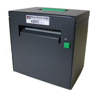
Related Manuals for Microcom 428TC


Summary of Contents for Microcom 428TC
- Page 1 MODEL 428TC DIRECT THERMAL PRINTER OPERATOR’S MANUAL PART NUMBER: 880041-0141 September 12, 2013 CPC Copyright © 2013 by Microcom Corporation, Lewis Center, Ohio – All rights reserved. Printed in the United States of America...
- Page 3 For this reason, specifications are subject to change without notice. Liability Disclaimer Microcom Corporation makes every effort to assure that all information and specifications contained in this manual are accurate; however, mistakes are sometimes made. Microcom Corporation shall not be liable for any damages resulting in the use or misuse of this product.
-
Page 5: Table Of Contents
3.12.4.1 Entering Diagnostic Mode..............3-31 3.12.4.2 Statistics Label..................3-31 3.13 TOF Sensor ....................... 3-32 3.14 Media Roll Holder Option ................... 3-34 3.15 Ticket Catch Tray Option ................... 3-34 3.16 Wristband Media Adapter Option ............... 3-35 428TC Operator’s Manual - 880041-0141... - Page 6 Black Box Reverse Video................4-21 4.8.2 Auto Reverse Video ..................4-22 CHAPTER 5 PRINTER COMMANDS ............5-9 Special Printer Control Codes ................5-9 5.1.1 Enquiry Responses ..................5-11 Printer Configuration Commands ............... 5-13 5.2.1 Software Switches..................5-13 428TC Operator’s Manual - 880041-0141...
- Page 7 Peel-and-Dispense Operation..............5-52 5.10.3 Load Advance/Retract Distance and Load Advance Delay......5-52 5.11 View Printer Configuration and Statistics ............5-52 5.12 Memory Commands................... 5-53 5.13 Printer Code Update ..................5-58 5.14 Miscellaneous Commands ................. 5-59 428TC Operator’s Manual - 880041-0141...
- Page 8 GS1 Databar, TCI 35 ..................8-3 8.1.11.1 GS1 Databar Omni-Directional .............. 8-4 8.1.11.2 GS1 Databar Truncated ................. 8-4 8.1.11.3 GS1 Databar Stacked ................8-4 8.1.11.4 GS1 Databar Stacked Omni-directional ..........8-4 8.1.11.5 GS1 Databar Limited................8-5 428TC Operator’s Manual - 880041-0141...
- Page 9 10.2 Thermal Printer Cleaning Card ................10-1 10.3 Internal Cleaning....................10-3 10.4 Print Head Maintenance..................10-4 10.5 Replacing the Drive Roller ................. 10-5 10.6 Adjusting Printhead Pressure................10-7 CHAPTER 11: TROUBLESHOOTING ............. 11-1 11.1 Troubleshooting Tips..................11-1 428TC Operator’s Manual - 880041-0141...
- Page 10 List of Figures ......................12-7 List of Tables......................12-9 APPENDIX....................13-1 Appendix A: Limited Warranty.................. 13-1 Appendix B: RMA Procedure ................... 13-3 Appendix C: ^D Command Summary ............... 13-5 Glossary........................13-23 Appendix D: User Notes ..................13-27 428TC Operator’s Manual - 880041-0141...
- Page 11 Introduction The Model 428TC printer has been designed to provide solutions for the ticketing industry. The printer uses the same reliable print mechanism found in the Model 428M printer. The lockable printer box not only houses the media but protects your ticketing investment as well.
- Page 12 428TC Operator’s Manual - 880041-0141...
-
Page 13: Chapter 1: Printer Specifications
8”/sec. (203 mm/sec.) 203 DPI = 4.098” (104.10mm); 832 dots Maximum Print Width 300 DPI = 4.252” (108 mm); 1,280 dots Maximum Print Length 50” (1,270 mm) Minimum Print Length 0.25” (6 mm) Table 1-2 Printing Specifications 428TC Operator’s Manual - 880041-0141... -
Page 14: Table 1-3 Media Specifications
*NOTE: The printers may print on thicker media types depending on the pliability of the material; however, this requires testing and evaluation. Contact your authorized Microcom Corporation representative for additional information regarding testing and evaluation of thicker or rigid media types. Table 1-3 Media Specifications 428TC Operator’s Manual - 880041-0141... -
Page 15: Chapter 2: Features And Options
Features and Options 2.1 Fonts 7 (203 DPI) smooth bitmapped alpha-numeric fonts from 6pt to 14pt. TrueType® font capability using Microcom Corporation utility program. 19 downloadable standard font set. All bitmapped fonts expandable in height and width. -
Page 16: Special Features
Heavy Duty Rotary Cutter Centronics Parallel Port Ethernet Port Pre-Stock Out Sensor Assembly Low Paper Sensor Assembly Wristband Option Paper Supply Holders Media Catch Trays Cleaning kit 428TC Operator’s Manual - 880041-0141... -
Page 17: Figure 3-1 Typical Printer Accessories
After the printer is removed from the container(s), verify that all the items on the packing list are present and in good condition. The picture below (See Figure 3-1) shows a 428TC and optional power cord. Your shipment may contain different items. -
Page 18: Figure 3-2 Printer Rear Panel
If XON/XOFF handshaking is used, the only signals that the printer requires are the RXD, TXD, and GND signals. If the hardware handshaking is used, then the CTS and RTS signals are required. The other signals are offered in the event that the host computer would require them. 428TC Operator’s Manual - 880041-0141... -
Page 19: Table 3-1 Rs-232 Cable Configurations
RS-232 Cable Configurations USB Communication Interface The 428TC printer provides a single USB port for communication to a host device. In order to communicate with the printer, the USB driver must be installed on the host computer. This may be downloaded at http://www.microcomcorp.com/drivers.htm. The Windows... - Page 20 Connect the power cable and the USB cable to the printer and turn the printer on. If already connected, disconnect USB and then reconnect the USB. The FTDI USB device should now recognize and install. 428TC Operator’s Manual - 880041-0141...
-
Page 21: Parallel Communication Interface
192.168.200.3, a NET mask of 255.255.255.0, and a local port of 9100. 3.6.1 Device Installer After starting the Device Installer software, you will see a screen similar to the picture below. Select the Search button to search for the XPORT device. 428TC Operator’s Manual - 880041-0141... - Page 22 Select Assign a specific IP address and select Next. This screen allows you to assign the IP Address and the Subnet Mask. You will need to obtain these two items from your network administrator and select Next. 428TC Operator’s Manual - 880041-0141...
- Page 23 Prolific USB to Serial driver must be installed. The process below shows how to configure the Ethernet port using Hyperterminal. Connect to the printer using a Serial or USB connection. Install media/paper into the printer. 428TC Operator’s Manual - 880041-0141...
- Page 24 Turn the printer ON with the print button pressed and held in. Release the button after the printer starts to feed media. Open a Hyperterminal session and type TEST for the name, select OK. Select the COM port that you are using to communicate and then select OK. 428TC Operator’s Manual - 880041-0141...
- Page 25 You should see information from the printer reported to the screen if communicating properly. Type a ^A1^D108 followed by the Enter key to change the active port to Ethernet. Power cycle the printer and the unit should be configured for Ethernet operation. 428TC Operator’s Manual - 880041-0141...
-
Page 26: Cash Drawer Option
Please note that the drivers should be installed before connecting the printer and turning it on. The first step would be to execute the MICPrinter installer (MICPrinter-Setup.exe) to install the utility onto your system. The first screen will be similar to: 3-10 428TC Operator’s Manual - 880041-0141... - Page 27 Chapter 3 Getting Started Click the Next button to continue. You will see a screen similar to this showing the progress of the installation. 428TC Operator’s Manual - 880041-0141 3-11...
- Page 28 Connect the power cable and the USB cable to the printer and turn the printer on. The FTDI USB device should try to install. If it is unable to install, please manually install the by following the example below. Select YES to install the communications driver. 3-12 428TC Operator’s Manual - 880041-0141...
- Page 29 The Micoption GUI may now be configured for the printer being used. You may access the Micoptions GUI from either the PRINTERS and FAXES folder and select Micprinter\Properties\Advanced Options\Setup Printer or START button\Programs\Micoptions\Micoptions. Micprinter listed under the Printers and Faxes folder. 428TC Operator’s Manual - 880041-0141 3-13...
- Page 30 Select the COMM port communication port. that the USB # that the FTDI device This should be disabled device is is connected to. if using the command detected on. line. 3-14 428TC Operator’s Manual - 880041-0141...
- Page 31 Export the form to save the setup and select Import to use an existing setup. Media and Error monitors and the printer ability to insert commands configurations or files into the data stream. 428TC Operator’s Manual - 880041-0141 3-15...
- Page 32 The Detect Hardware button is used to read settings from the printer. When the Autodetect is enabled, the driver will communicate to the printer and automatically set the Internal Parameters section. 3-16 428TC Operator’s Manual - 880041-0141...
- Page 33 The Internal Parameters section is set based on the printer being used. Please use the table below to determine the proper values if the Autodetect and AutoCalc and not checked. 428TC Operator’s Manual - 880041-0141 3-17...
- Page 34 300 dpi 424M 1280 203 dpi 424 300 dpi 424 1280 203 dpi 428TC, TC, TM Black line 300 dpi 428TC, TC, TM Black line 1280 203 dpi 428TC, TC, TM Die-cut, Blow- hole, Continuous 300 dpi 428TC, TC, TM Die-cut, Blow-...
- Page 35 To create a new form, check the “Create a new form” check box, fill in the Form name, Form description and remember to press Save Form to save it! After you have created the appropriate forms you need. Press OK Double click on the MICPrinter and you should see: 428TC Operator’s Manual - 880041-0141 3-19...
- Page 36 If we were printing any files they would be listed here. From the Printer drop down menu select Properties. The properties pages are displayed. The appropriate form size for the media we are using with the printer is set within this screen. Select Printing Preferences. 3-20 428TC Operator’s Manual - 880041-0141...
- Page 37 Press OK once finished Select the Paper Size (form size) being used. Select the Print Resolution of the printer under the Print Quality. Press the OK to continue. Now we return to the MICPrinter Properties page. 428TC Operator’s Manual - 880041-0141 3-21...
- Page 38 MICPrint Configuration utility -p<communication_port> - Send the communication port to the printer directly over-riding registry and configuration file -d<working_directory> - Directory for use with temporary files 3-22 428TC Operator’s Manual - 880041-0141...
- Page 39 0 - success -1 - unable to open image file -2 - unknown image file type -3 - unable to allocate memory -4, -9, -10, -12, -13. -31 - unknown error -5 - unsupported image resolution 428TC Operator’s Manual - 880041-0141 3-23...
- Page 40 IF ERRORLEVEL -8 GOTO LabelN08 IF ERRORLEVEL -9 GOTO LabelN09 IF ERRORLEVEL -10 GOTO LabelN10 IF ERRORLEVEL -11 GOTO LabelN11 IF ERRORLEVEL -12 GOTO LabelN12 IF ERRORLEVEL -13 GOTO LabelN13 IF ERRORLEVEL -14 GOTO LabelN14 3-24 428TC Operator’s Manual - 880041-0141...
- Page 41 :LabelN05 echo UNSUPPORTED IMAGE RESOLUTION GOTO END :LabelN06 echo ERROR OPENING OUTPUT FILE GOTO END :LabelN08 echo ERROR OPENING BINARY OUTPUT FILE GOTO END :LabelN09 echo UNKNOWN ERROR GOTO END :LabelN10 echo UNKNOWN ERROR 428TC Operator’s Manual - 880041-0141 3-25...
- Page 42 LOW STOCK PRIOR TO PRINTING GOTO END :LabelN30 echo LOW STOCK DETECTED POST PRINTING GOTO END :LabelN40 echo PRE-PRINT COMMAND STRING ERROR GOTO END :LabelN41 echo PRE PRINT COMMAND FILE ERROR GOTO END 3-26 428TC Operator’s Manual - 880041-0141...
-
Page 43: Loading Media
For more details on this feature, please refer to Chapter 5, Autoload Commands. 428TC Operator’s Manual - 880041-0141 3-27... -
Page 44: Figure 3-4 Loading Media
This section provides a description to familiarize you with the basic function of the Print Button and the Status Indicator Light. Status Light Print Button Figure 3-5 Print Button and Status Indicator Light 3-28 428TC Operator’s Manual - 880041-0141... -
Page 45: Table 3-2 Print Button Description
Power Spike or low voltage on the AC line. (The printer will remain in this mode until the condition is removed and the printer power is cycled.) Flashing Amber Printer is PAUSED, Table 3-3 Status Indicator Light Description 428TC Operator’s Manual - 880041-0141 3-29... -
Page 46: Printer Modes
There are several ways that the operator can control the output of the printer. The printer will display either solid or flashing AMBER depending upon the mode of operation. Also, the printer will display a solid AMBER during a FLASH update operation. 3-30 428TC Operator’s Manual - 880041-0141... -
Page 47: Diagnostic Mode
(^D32). These are the only ways to get out of the DIAGNOSTICS mode. 3.12.4.2 Statistics Label The Statistics Label may be printed either by entering the DIAGNOSTICS Mode or sending the Printing Statistics Command. 428TC Operator’s Manual - 880041-0141 3-31... -
Page 48: Figure 3-6 Status Label (Examples)
The sensor is set to the maximum detection at the factory. This pot may be used to decrease sensor range to avoid false reflections from stationary objects such as a cutter. 3-32 428TC Operator’s Manual - 880041-0141... - Page 49 Chapter 3 Getting Started The TOF Sensor is located in front of the cutter assembly TOF sensor when the cutter assembly is not installed. Figure 3-7 TOF (Top-Of-Form) Sensor 428TC Operator’s Manual - 880041-0141 3-33...
-
Page 50: Figure 3-8 Rolled Media Holder
The printer may be configured with an optional ticket catch tray that is used to catch the printed tickets. The trays are available in a couple of standard sizes. Figure 3-9 Ticket Catch Tray 3-34 428TC Operator’s Manual - 880041-0141... -
Page 51: Figure 3-10 Wristband Media Adapter
Wristband Guide Loosen locking nut and slide guide into place and retighten into place Insert into media guide making sure that it is flush against the green media guide Figure 3-10 Wristband Media Adapter 428TC Operator’s Manual - 880041-0141 3-35... - Page 52 Getting Started Chapter 3 3-36 428TC Operator’s Manual - 880041-0141...
-
Page 53: Chapter 4: Designing Labels Using Lds
Items required: A computer with a Prolific Technologies USB driver installed. (Contact your Microcom Corporation representative for more details.) A USB cable with Type-A (host computer) and Type-B (printer) connectors. A VT-100 terminal emulation program such as HyperTerminal™. -
Page 54: Format Creation
“Shift” key and the “6”) plus the alpha character. See Chapter 5 for additional information regarding control codes and printer commands. There are some special features offered by the printer that assist in label design. For example, the auto-size command (^A2^D39 <CR>) provides most of the header format 428TC Operator’s Manual - 880041-0141... -
Page 55: Label Design: An Overview
The next line is the header information that sets the label size and other pertinent information. The next five lines are layout and configuration for each data field in the format. 428TC Operator’s Manual - 880041-0141... -
Page 56: Figure 4-2 3X3 Sample Label
For example, a 4” X 6” label printed with a 300 DPI print head would be 1200 (4 X 300 dots in the horizontal or “X” direction, and 1800 (6 X 300) dots in the “Y” direction. 428TC Operator’s Manual - 880041-0141... - Page 57 HFM parameter, they will be ignored and will not print. The HFM was set to a value of 5 in the format used to create the sample in Figure 4-2. This 428TC Operator’s Manual - 880041-0141...
-
Page 58: Lsx (Print Head Size X)
Generally, better print quality is achieved by printing at lower speeds, however this is also dependent on the media and contrast settings as well. Labels per minute can be calculated by the equation below: IPS x 60 seconds Labels per Minute Label Height 428TC Operator’s Manual - 880041-0141... -
Page 59: Table 4-1 Dps Values
SPG parameter of the header when the default AGD of “1” is entered in the header. This means that fields that are left blank or text data for the associating format fields are left empty will not print. 428TC Operator’s Manual - 880041-0141... -
Page 60: Table 4-2 Dot To Gap Parameters
LSY is greater than the D2G parameter value, the D2G value is used. Registration Sensor/Print Head DPI D2G Value Transmissive (GAP) / 203 DPI Reflective (Blackline) / 203 DPI Transmissive (GAP) / 300 DPI Reflective (Blackline) / 300 DPI Table 4-2 Dot to Gap Parameters 428TC Operator’s Manual - 880041-0141... - Page 61 The SPG may also be determined by adding a line at dot row #1 using Line Draw (See Section 4.7) and adjusting the SPG number up and down to get desirable registration with the line printing at the bottom edge of the media. 428TC Operator’s Manual - 880041-0141...
-
Page 62: Ofx (Offset X Direction)
LCB of 0 for die-cut labels. AGD of 1 step. SPG of 385 for proper placement of the next label. No X offset. No Y offset. <CR> A carriage return must follow the header. 4-10 428TC Operator’s Manual - 880041-0141... -
Page 63: Label Format Fields
1, 640, 650, 8, 1, , , 0 Feed Direction 4” PRINT HEAD Microcom Corporation Thermal Printing Solutions 012345 X beginning This is the origin; 1,1 Y beginning Figure 4-4 Label Format Field Elements 428TC Operator’s Manual - 880041-0141 4-11... -
Page 64: Tsn (Text String Number)
For example, a TCI of “1” for the text string data “012345” would print the text “012345” while a TCI of “15” would produce an “Interleaved 2 of 5” symbol. 4-12 428TC Operator’s Manual - 880041-0141... -
Page 65: Table 4-3 Tci Values
Codabar Symbol Code 93 Symbol PDF-417 Symbol Datamatrix Symbol Intelligent Mail Barcode Planetcode Symbol UCC/EAN 128 Symbol Text with EAN 128 Information * Human Readable - Refer to Chapter 8 Table 4-3 TCI Values 428TC Operator’s Manual - 880041-0141 4-13... -
Page 66: Cgn (Character Generator Number)
Downloadable fonts must be stored in two separate directions; 0 and 90 degrees. This means that the 0 degree fonts should be used with 0 and 180 degree rotations while the 90 degree fonts used with 90 and 270 degree rotations in order to achieve correct printing. 4-14 428TC Operator’s Manual - 880041-0141... - Page 67 Swiss™721 Bold 90 degree Swiss™721 Bold 0 degree Swiss™721 Bold 90 degree Swiss™721 Bold 0 degree Swiss™721 Bold 90 degree Swiss™721 Bold 0 degree Swiss™721 Bold 90 degree OCR-A Normal 0 degree OCR-A Normal 90 degree 428TC Operator’s Manual - 880041-0141 4-15...
-
Page 68: Embedded Bar Codes
Code 128 & UCC / EAN 128 * 40 % 0123 0123 Codabar 0123 0123 Code 93 0123 AS-10 0123 0123 0123 Maxicode (CGN = Mode) 0123 0123 0123 MSI (Modified Plessey) 0123 Table4-6 CGN—Bar Code Symbologies 4-16 428TC Operator’s Manual - 880041-0141... -
Page 69: Table 4-7 Fo & Fj Character Starting Positions
3 – Right justified below the base-line 4 – Centered on the Y axis, right of X coordinate 5 – Centered on the Y axis, left of the X coordinate Table 4-7 FO & FJ Character Starting Positions 428TC Operator’s Manual - 880041-0141 4-17... -
Page 70: Cmx (Character Multiplier X Direction)
AN parameter is set to a value of “2”, the character spacing will be fixed / non-proportional. A setting of “3” will print both fixed/non-proportional character spacing and reversed text. Proportional Character Spacing Reverse Video 4-18 428TC Operator’s Manual - 880041-0141... -
Page 71: Figure 4-5 Line Draw Sample
This is a list of the first label format field element mnemonics for the sample label in Figure 4-5: TSN, XB, YB, CC, TCI, CGN, FO, FJ, CMX, CMY, CS, TSP, , , AN 1, 340, 712, 600, , , , 0 428TC Operator’s Manual - 880041-0141 4-19... - Page 72 CC (Character Count) This element is not used in line draw. No value is necessary, however, a comma needs to be entered to acknowledge the position. TCI (Text Conversion Identifier) The TCI is always set to a “6” for line draw. 4-20 428TC Operator’s Manual - 880041-0141...
-
Page 73: Reverse Video
Format Fields defining the line draw and the text fields. The size of the box is not defined by the text. Adjustment to the size of the box must be made by adjusting the line draw coordinates. 428TC Operator’s Manual - 880041-0141 4-21... -
Page 74: Auto Reverse Video
It is possible to create a reverse video effect with barcodes using this method. ^D57 5,1280,900,19,38,7,0,1,385,0,0 Microcom 1,640,700,8,1,5,0,4,2,2,,,,,8 2,640,591,11,1,5,0,4,2,2,,,,,8 3,640,443,26,1,5,0,4,,,,,,,8 Corporation 4,640,296,6,1,5,0,4,,,,,,,8 4,640,148,6,16,3,,4,3,75,,,,,0 ^D56 Thermal Printing Solutions Microcom Corporation 012345 Thermal Printing Solutions 012345 Figure 4-8 Auto Reverse Video Sample 4-22 428TC Operator’s Manual - 880041-0141... -
Page 75: Chapter 5 Printer Commands
“control B” is shorter, it is easier to use in direct terminal mode. In general it is better to use the ^D2 command sequence inside a file or program to assist in trouble-shooting the format. 428TC Operator’s Manual - 880041-0141... - Page 76 This command is used to request the printer’s status and is very similar to the ^E command. The biggest difference between this command and the ^E is that when printers are 5-10 428TC Operator’s Manual - 880041-0141...
-
Page 77: Enquiry Responses
If the STL Emulation (Switch Bank #6 bit 2; D26 command) is enabled, the printer will report STL type responses instead of the normal LDS status responses. The STL mode continues to follow the Text and/or Byte mode rule above but will only Display the Decimal codes. 428TC Operator’s Manual - 880041-0141 5-11... -
Page 78: Table 5-1 Stl Status Responses
Printer entered and recovered from a >BROWNOUT RECOVERY< brownout power condition Timeout failure occurred using the D149 >FAIL TIMEOUT< Image Print Mode Incorrect size of the image was received >FAIL SIZE< using the D149 Image Print Mode 5-12 428TC Operator’s Manual - 880041-0141... -
Page 79: Printer Configuration Commands
Enquiry Response: This determines what the printer will send back in response to an enquiry command. 00 = Control Codes 10 = Text Equivalent Control Codes: This position sets how the printer handles incoming control codes. 1 = Ignore Incoming Control Codes 428TC Operator’s Manual - 880041-0141 5-13... -
Page 80: Software Switch #2
1 = Enable (>RESTARTED< on first inquiry then >READY<) 0 = Disable (Always responds with >READY<) Button Use: If set to a “1”, the printer will disable the Print Button. 1 = Disable 0 = Enable 5-14 428TC Operator’s Manual - 880041-0141... -
Page 81: Software Switch #3
A setting of 0 (active HIGH) will report the >INPUT 1< message if a reflection is detected. 1 = Send >INPUT 1< active LOW 0 = Send >INPUT 1< active HIGH 428TC Operator’s Manual - 880041-0141 5-15... -
Page 82: Software Switch #4
Change SW4: Software Switch #4. ^AB12345678 (each bit is represented by a numeric position number) Position: Slashed Zeros: If enabled, the printer will print a slash through the embedded zero (“0”) characters. 1 = Enable 0 = Disable 5-16 428TC Operator’s Manual - 880041-0141... -
Page 83: Software Switch #5
^AB12345678 (each bit is represented by a numeric position number) Position: 1 Single Button Press Error Clear: If enabled, error conditions are cleared with a single press of the print button after reloading the printer with more media. 428TC Operator’s Manual - 880041-0141 5-17... - Page 84 0 = Disable AutoLoad Type of AutoLoad: This bit determines whether the AutoLoad function uses the Top-Of-Form sensor (TOF), or if it uses the Form Feed technique. 1 = AutoLoad + TOF 0 = AutoLoad + FF 5-18 428TC Operator’s Manual - 880041-0141...
-
Page 85: Software Switch #6
This message will only be reported if media is not detected by the internal sensors following a power on, reboot command (^D143), and/or restart (^D32) commands. 428TC Operator’s Manual - 880041-0141 5-19... - Page 86 The 48-466 graphic structure is used when the emulation command is enabled and discussed in greater detail the 48-466 Operators manual. c) The ^D59 command allows format slots 121 to 128 to be overwritten to when the emulation command is enabled. 5-20 428TC Operator’s Manual - 880041-0141...
- Page 87 (24VDC) and may be independently controlled. The ^D150 command is used to report the current status of the inputs. When issued, the printer will send the host the current status of the 4 428TC Operator’s Manual - 880041-0141 5-21...
- Page 88 The outputs are entered in as a HEX value that is equal to a binary number with the outputs in the following order; 4321. Command Syntax: ^D68<CR>0n<CR> n = the hex value from 0 to F. 5-22 428TC Operator’s Manual - 880041-0141...
- Page 89 NOTE: Default power up will disable I/O mode. The P17 and P21 connectors are 8 pin MTA50 AMP part number #1445350-8 and Microcom Corporation part number 510188-0008. The pin out is as follows (the square pad denotes pin one on the PCB): Connector P17 is the input port.
- Page 90 TOF at normal speed. The timer is then reset and starts to count down once again. The default time interval is set to 4 hours or 144400 seconds. The interval may be adjusted by using the D156 command. 5-24 428TC Operator’s Manual - 880041-0141...
-
Page 91: Software Switch #7
D158 command. The error will be acknowledged at the end of printing. This will work with all media (continuous, black line, and gap). 1 = Enable Finish Mode 0 = Disable Finish Mode 428TC Operator’s Manual - 880041-0141 5-25... -
Page 92: Software Switch #8
1320. It is this changed value that will be reported (^D148) and used as blsy. The tables are based on ticketing industry stock sizes off: 2” 2½” 3” 3¼” 3½” 4” 4½” 5” 5½” 5 5/8” 6” 6½” 7” 11” 5-26 428TC Operator’s Manual - 880041-0141... - Page 93 To see all of the table and user values enter ^A0^D170 [CR] Using one of these smart autosize modes gives the user single dot accuracy in using Boca autosize to find blsy. Reserved 428TC Operator’s Manual - 880041-0141 5-27...
-
Page 94: Communication Port Configuration
9600 bps 19200 bps 38400 bps 57600 bps 115200 bps 230400 bps (only used for D149 Image Mode) 460800 bps (only used for D149 Image Mode) 921600 bps (only used for D149 Image Mode) 5-28 428TC Operator’s Manual - 880041-0141... -
Page 95: Set Serial Port Source Command (Volatile - ^D109)
The ^D171 command is used to open a Telnet session with the Ethernet (Xport Device) port to gain access to its configuration settings. The Ethernet port is set to an IP Address of 192.168.200.3 and Net Mask of 255.255.255.0 on port 9100 by default at the factory. If this 428TC Operator’s Manual - 880041-0141 5-29... -
Page 96: Change Setup
A netmask defines the number of bits taken from the IP address that are assigned for the host section. The unit prompts for the number of host bits to be entered, then calculates the 5-30 428TC Operator’s Manual - 880041-0141... -
Page 97: Print Head Size Commands
This command MUST be sent AFTER the dot density (dpi) is set with the ^D79 command. The only valid entries for XX are the numbers in the “# of Dots” column in the table above. 428TC Operator’s Manual - 880041-0141 5-31... -
Page 98: General Purpose I/O
The printer sends a byte of status data to its Ethernet interface using the same data format, and will only send the data when there is a change in status. The printer’s Ethernet interface will send the printer status byte to the HOST every few milliseconds. 5-32 428TC Operator’s Manual - 880041-0141... - Page 99 Sending the “Enable General Purpose Mode” command will set the printer up to go into General Purpose mode. The printer will NOT go into General Purpose Mode until a power cycle occurs to cause the data to be stored in 428TC Operator’s Manual - 880041-0141 5-33...
-
Page 100: Specialized Print Modes
Continuous sync mode is similar to single sync mode except after the label is printed the printer will immediately begin reprocessing the format to prepare another image for printing. If an external print signal is provided on the General Purpose print input, the printer will 5-34 428TC Operator’s Manual - 880041-0141... -
Page 101: Usb Image Print Mode
2. The Host then sends the printer the ^D149 command followed by the raw image size that has been converted by the bmp2mic rev 1.02 or later. Please note that the size is only terminated with a [CR] and the [LF] is not included. Example: ^D149[CR][LF]size[CR] 428TC Operator’s Manual - 880041-0141 5-35... -
Page 102: Contrast Adjustment Commands
Adjust Contrast Base: This non-volatile command is used to skew the entire contrast window (^D35). Contrast settings above 150 reduce the overall life of the printer. This command has a ^A range of 10 to 200%. 5-36 428TC Operator’s Manual - 880041-0141... -
Page 103: Slice Buffer Size And Set Starting Slice Number Commands
The printer will update and write the configuration to flash on normal power downs. This command may be used to start using certain non-volatile system parameters (head parameter and soft switch commands). 428TC Operator’s Manual - 880041-0141 5-37... -
Page 104: Registration Commands
The ^Ax selects either reflective or transmissive detection. Automatically sets the transmissive threshold value. Automatically sets the reflective threshold value. Set the Transmissive Dot2Gap Value: 5-38 428TC Operator’s Manual - 880041-0141... -
Page 105: Table 5-5 Transmissive Dot2Gap Values
^D47 is set to the proper setting for the media being used. When using media that contains a blackline for the registration mark, first execute the ^A1^D47<CR> command sequence before issuing the auto-size command or the results may be invalid. 428TC Operator’s Manual - 880041-0141 5-39... -
Page 106: Autoheader Commands
This command is a specialty media handling command that works when the correct media is used. Please contact your Microcom Corporation representative if you have any questions regarding the use of this command. When enabled the printer will autoload... -
Page 107: Autoload Media Commands
The printer will advance a blank label, based on the current or last processed label, before starting to print properly registered labels. These are the steps for AutoLoad + FF: 428TC Operator’s Manual - 880041-0141 5-41... -
Page 108: Autoload + Top-Of-Form
AutoLoad + FF. Soft switch #5, bit #3 selects the type of TOF sensor. The TOF may a REFLECTIVE style, or it may use a TRANSMISSIVE sensor for more accurate sensing. 5-42 428TC Operator’s Manual - 880041-0141... - Page 109 This command initiates a TOF operation: a) Media is advanced until the leading edge is detected by the reflective “Top Of Form” sensor, b) Media is retracted to place the leading edge of stock under the print head. 428TC Operator’s Manual - 880041-0141 5-43...
-
Page 110: Printing Commands
^D75 command will print the number of copies (the same label) specified by the “^Axx” sequence just like the ^D73 command. This command may also be used in conjunction with the ^D73 command. The batch of labels is printed 5-44 428TC Operator’s Manual - 880041-0141... -
Page 111: Label Header Parameter Override Commands
Please note that the ^D57 command clears most of the serial number commands. Therefore, all serial number commands should be placed after the ^D56 command or just prior to the ^D3 command. 428TC Operator’s Manual - 880041-0141 5-45... - Page 112 The printer will not decrement fields beyond 0. Fields that instructs the printer to decrement beyond 0 will be set to A sample format using the single serial number function: ^D57 <CR> 1,575,609,,25,35,0,1,285,0,0 <CR> 1,280,300,2,1,5 <CR> 5-46 428TC Operator’s Manual - 880041-0141...
-
Page 113: Text String Commands
This command is used when fixed data is used much like a template and only the variable data is to change. Pre-padded Text: This command is used to pre-pad text data. Any data 428TC Operator’s Manual - 880041-0141 5-47... - Page 114 ^D3 command to initiate printing. The printer will accept incoming text strings and print the label as soon as the number of strings equal the amount specified by the ^D64 command. 5-48 428TC Operator’s Manual - 880041-0141...
-
Page 115: Cutter Configuration Commands
LTS sensor. When using these modes, a second form will not print until the label is taken. The printer will report the >TAKE LABEL< message when the LTS detects media and then only >READY< when the form is taken. Kiosk Cutter Mode Disable Kiosk Cutter Mode. 428TC Operator’s Manual - 880041-0141 5-49... -
Page 116: Kiosk Cutter Advance Distance Command
A Partial Cut leaves a thin piece of media in the center after the cut cycle is finished. This small piece of uncut stock holds the media together and the printer waits until the media is removed before printing the next label. The 5-50 428TC Operator’s Manual - 880041-0141... -
Page 117: Cutter Hold-Off
Note: Advance distance must be set at “0” for this command to function. Cutter Hold-off: X represents the number of cuts to skip on the first X labels following a Top of Form. 428TC Operator’s Manual - 880041-0141 5-51... -
Page 118: Dispensing Commands
Load Advance Delay: The ^Axx specifies the amount time, in milliseconds, that the printer will delay the repositioning or retraction of the media. For Example, “^A1000^D96 <CR>” would delay for a period of one second. 5-52 428TC Operator’s Manual - 880041-0141... -
Page 119: View Printer Configuration And Statistics
The ^Axx selects the memory slot (1- 128) into which the format is to be saved. A format file must be terminated by an ESC (HEX 1B) or “[“(left bracket) character to save the format. Sample format saved to RAM slot #1: ^A1^D59 ^D57 5,1280,900,20,40,7,0,1,405,0,0 1,640,650,12,1,5,0,4,2,2,,,,,0 ^D56 428TC Operator’s Manual - 880041-0141 5-53... - Page 120 [1,176] Slot #1 of FORMAT flash has a FORMAT file that is 176 bytes. Format Flash Memory Available - 65359 There are 65,359bytes of FORMAT flash open. Label Memory - [size, available] [43231,41618] The difference is the amount of memory to process current format. 5-54 428TC Operator’s Manual - 880041-0141...
- Page 121 FLASH before storing a new FORMAT into the Slot. xxyy 133 Save Compressed GRAPHICS to FLASH. (See Chapter 6, Downloadable Graphics) Delete a GRAPHIC from FLASH. ^A0 deletes all GRAPHIC files in FLASH 428TC Operator’s Manual - 880041-0141 5-55...
- Page 122 FONT in FLASH must have a unique CGN #. If a FONT is downloaded that has the same CGN # as a FONT that is already stored in FLASH, then an error message is sent back indicating a Duplicate CGN error. 5-56 428TC Operator’s Manual - 880041-0141...
- Page 123 This command tells the printer to take the Label FORMAT file in Slot #xx and build up its image in the printer’s slice buffer. After this command is finished, the label may be printed by sending the ^C print command. 428TC Operator’s Manual - 880041-0141 5-57...
- Page 124 Please note that this command may take some time (depending on how much is stored). During this time the printer will not respond to commands. The printer may appear to be locked up until the command finishes. 5-58 428TC Operator’s Manual - 880041-0141...
-
Page 125: Printer Code Update
^A62519^D7 command will update the printer’s bootloader, application, and embedded font set. This process requires some interactivity with the printer and failure to follow the proper process will cause the printer to become inoperable. Please contact your Microcom Corporation Representative for more information. 5.14... - Page 126 The value for X represents how long the takeup motor will run, in milliseconds, after printing has stopped. This command is a volatile command with a default of 0. The ^A1^D145 command lists the current setting under the Post Takeup Time. 5-60 428TC Operator’s Manual - 880041-0141...
- Page 127 Sensor Status Byte: This command is used to report the real time sensor status of all the printer sensors. When the ^D163 command is issued, the printer returns a byte status that is defined below. 428TC Operator’s Manual - 880041-0141 5-61...
-
Page 128: Table 5-7 Sensor Status Byte Definitions
0 = No Stock Detected Transmissive 1 = No Stock Detected Registration Sensor 0 = Stock Detected Reflective 1 = No Stock Detected Registration Sensor 0 = Stock Detected Table 5-7 Sensor Status Byte Definitions 5-62 428TC Operator’s Manual - 880041-0141... -
Page 129: Chapter 6: Downloadable Graphics
Select an open slot number for storage. Use ^D119 to determine which slots are open. 5) Limit The maximum print width (in dots). Use ^D29 to determine print head size. 6) Destination Use “0” for FLASH and “1” for RAM. 428TC Operator’s Manual - 880041-0141... -
Page 130: Bmp2Mic.exe Graphic Conversion Utility Procedure
You may name the <outfile> anything you wish as long it is less than 8 characters. An extension is not necessary. 3. Conversion is complete. Converted GRAPHIC file is ready to download to printer. 428TC Operator’s Manual - 880041-0141... -
Page 131: Graphic Download Methods
6.5 Advanced GRAPHIC Format Conversion for Programmers The following sections are provided to developers who wish to create usable GRAPHIC images within their own applications. Commands in the following section are not typically seen for users using Microcom GRAPHIC utilities. 428TC Operator’s Manual - 880041-0141... -
Page 132: Save Compressed Graphics To Ram (D107)
GRAPHIC uses, not the number of bytes that will actually be transmitted. Due to compression, the number of bytes transmitted will normally be less than this number. <Image Data> is the compressed binary image. 428TC Operator’s Manual - 880041-0141... -
Page 133: Binary Compression Algorithm
(4 X 256)+1+107 = 1132 6.5.4 Uncompressed FONT to RAM (^D104) This command allows graphic and/or font images (fonts must be less than 64KB uncompressed) to be transmitted in ASCII-HEX, thereby allowing all data to pass over 7 or 428TC Operator’s Manual - 880041-0141... -
Page 134: Figure 6-1 Ascii-Hex Conversions
All data is stored in binary form. Multi-byte values are stored least-significant-byte first. The method illustrated below allows graphic images to span 64KB memory segments. When using graphics over 64KB, the printer will determine the number of 64KB slots 428TC Operator’s Manual - 880041-0141... - Page 135 2d array. The most significant bit of the first byte in each row, prints as the right most dot of the character, and the first row is the bottom row when printed. 428TC Operator’s Manual - 880041-0141...
-
Page 136: Downloadable Graphics Commands
Deletes the graphics in slot #XX Save GRAPHICs or FONTs into RAM Memory without Compression: This command is intended for legacy support only and Microcom Corporation recommends either the ^D104 or ^D107 commands. Fonts must be less than 64KB for this command to function. -
Page 137: Chapter 7: Downloadable Fonts
TCI must be set to an “8” for volatile downloadable fonts and the CGN refers to the memory slot location of the downloaded font. Nonvolatile fonts are accessed thru TCI “7”. 428TC Operator’s Manual - 880041-0141... -
Page 138: Sfp2Mic.exe Program
7-bit data connections. The uncompressed (^D104) is usable on either 7 or 8-bit connections and is more flexible but encodes using ASCII-HEX. This results in a much larger file size. Microcom Corporation recommends the use of the compressed format when possible. -
Page 139: Save Compressed Font To Ram (D127)
This command allows graphic and/or font images (fonts must be less than 64KB uncompressed) to be transmitted in ASCII-HEX, thereby allowing all data to pass over 7 or 8-bit data connections. This command is usable on data connections that support either 7 or 8-bit data. 428TC Operator’s Manual - 880041-0141... -
Page 140: Save Fonts To Flash (^D135)
FONT download for FLASH memory is coming. The download will be 2 sectors long, and the printer will access the FONT in FLASH memory using CGN #24 and TCI #7. The ^A0124^D135 command will be right at the 428TC Operator’s Manual - 880041-0141... -
Page 141: Font Structure
All data is stored in binary form. Multi-byte values are stored “least significant byte” first. The printer can store a font of approximately 64KB or less in any one memory slot location. 428TC Operator’s Manual - 880041-0141... -
Page 142: Downloadable Font Command Summary
7.6 Downloadable Font Command Summary The following commands refer to the use of downloadable fonts and graphics: 428TC Operator’s Manual - 880041-0141... - Page 143 80 HEX. This command supports GRAPHICS over 64KB. Load GRAPHIC or FONT into RAM Memory without Compression: This command is intended for legacy support only and Microcom Corporation recommends either the ^D104 or ^D107 commands. Fonts must be less than 64KB for this command to function.
- Page 144 Downloadable Fonts Chapter 7 428TC Operator’s Manual - 880041-0141...
-
Page 145: Chapter 8: Bar Codes
UPC-E bar codes do not use inter-character spacing, therefore the character spacing (CS) element must be defaulted. The chart listed in Table 14 illustrates how the 11 digits are reduced to only 6 using the “zero suppression” compression. 428TC Operator’s Manual - 880041-0141... -
Page 146: Table 8-1 Upc-E Zero Reduction Format
(“*”) character, which is reserved for this purpose. This symbology uses 2:1, 3:1, 4:2, 5:2, and 8:3 ratios, which may be selected using the CGN parameter. Although most specifications require a specific inter-character 428TC Operator’s Manual - 880041-0141... -
Page 147: European Article Numbering System 13 (Ean-13), Tci 20
Databar has been identified to solve problems in the grocery industry and in healthcare, where items are too small to allow for older barcode symbology. The printer should have binary compression disabled before using GS1 Databar. 428TC Operator’s Manual - 880041-0141... -
Page 148: Figure 8-1 Gs1 Databar Omni-Directional
The barcode contains a separator pattern, containing no data, which has a height equal to 3 times the X dimension. This symbology may be scanned omni-directionally. This symbology does not allow for human readable text with the barcode. 428TC Operator’s Manual - 880041-0141... -
Page 149: Figure 8-5 Gs1 Databar Limited Sample
These are the 7 parameters that MUST follow the ^D114 command: 1) Type of GS1 Databar barcode 2) Multiplier 3) Segments per row 4) X undercut 5) Y undercut 6) Separator Height 7) Data to be encoded 428TC Operator’s Manual - 880041-0141... -
Page 150: Figure 8-7 Gs1 Databar Sample Label Format
Postnet is a numeric-only symbology that is commonly used in postal application to sort mail. The five-digit zip or five-digit zip plus four-digit extension may be used to generate this Postnet (TCI 36) bar code. Example: 12345 or 12345-1234. 428TC Operator’s Manual - 880041-0141... -
Page 151: Postnet (Zip+6), Tci 37
Zip Code - 9 digits The data string associated with a MaxiCode field shall be formatted according to the Mode selected (2-6). Mode 2 Mode 2 may have either of the following formats: Format 1 428TC Operator’s Manual - 880041-0141... - Page 152 Table 15, and occupy only one character in the encoded string. Mode 6 Mode 6 may encode any string up to 93 characters. Control characters are specified in Table 15 on the next page, and occupy only one character in the encoded string. 428TC Operator’s Manual - 880041-0141...
-
Page 153: Table 8-2 Maxicode Control Code Equivalents
The printer will automatically choose the most efficient subset and insert the appropriate special function code listed in Table 16. It is possible to force a subset change by inserting the appropriate code while in automatic 428TC Operator’s Manual - 880041-0141... -
Page 154: Figure 8-8 Code 128 Subset Switching
C the user must send the appropriate code (#n) to return to either subset A or B. ABC#3012345#5abc The “#5” The “#3” code, printer code, while while in defaults to in subset B, subset C, subset B switches to switches subset C. Figure 8-8 Code 128 Subset Switching 8-10 428TC Operator’s Manual - 880041-0141... -
Page 155: Codabar (Rationalized), Tci 42
The PDF-417 format command (^D77) is used to load the data as well as formatting instructions for the bar code and is placed on the first line of the format. 428TC Operator’s Manual - 880041-0141 8-11... - Page 156 This parameter is used to adjust the aspect ratio of the PDF-417 symbology. The value is entered in ratio format (height: width) and has a default value of 2:1. A carriage return character must be used to terminate this field. 8-12 428TC Operator’s Manual - 880041-0141...
-
Page 157: Figure 8-9 Pdf-417 Sample Format #1
The following format samples show how to generate a PDF-417 bar code: Sample Format #1: ^D77<CR> :PDF-417 bar code data^[ 3<CR> 30<CR> 0<CR> 0<CR> 0<CR> 2:1<CR> ^D57<CR> 2,575,609,,25,35,0,1,285<CR> Text string 1,190,300,1,46<CR> 2,190,200,11,1,5<CR> ^D56<CR> ^D2<CR> P<CR> Text string<CR> ^D3<CR> Figure 8-9 PDF-417 Sample Format #1 428TC Operator’s Manual - 880041-0141 8-13... -
Page 158: Figure 8-10 Pdf-417 Sample Format #2
The D164 command is used to receive and process the Datamatrix barcode with the elements discussed below. Once the Datamatrix barcode data is entered and processed, the barcode image may be placed using the normal format field by using a TCI of 47. 8-14 428TC Operator’s Manual - 880041-0141... - Page 159 Numeric Alphanumeric Binary Byte Symbol Size Capacity Capacity Capacity Auto 10 x 10 12 x 12 14 x 14 16 x 16 18 x 18 20 x 20 22 x 22 24 x 24 428TC Operator’s Manual - 880041-0141 8-15...
-
Page 160: Table 8-5 Data Matrix Configuration Parameters
Specification for Data Matrix ECC 200 requirements for additional information. Encoding Bits per Characters Scheme Character Double digit numeric A- ASCII ACSII values 0 – 127 Extended ASCII values 128-255 C- C40 Primarily Uppercase Alphanumeric 5.33 8-16 428TC Operator’s Manual - 880041-0141... -
Page 161: Table 8-6 Data Matrix Encoding Schemes
Edifact Encoding Scheme X12 encoding scheme includes 63 ASCII values (values from 32 to 94) plus an Unlatch character (binary 011111) to return to ASCII encoding. Edifact encoding encodes four data characters in three codewords. 428TC Operator’s Manual - 880041-0141 8-17... - Page 162 ^D164 <---------------------------------Start of Datamatrix Data 0 <----------------------------------------Width 0 <----------------------------------------Height 1 <----------------------------------------Rotation A <----------------------------------------Encoding 1 <----------------------------------------Barcode ID :This is the second datamatrix being printer in this format.^\<---------------------- Data to encode (from the : to ^\) 8-18 428TC Operator’s Manual - 880041-0141...
-
Page 163: Intelligent Mail Barcode, Tci 48
Once the Intelligent Mail barcode data is entered and processed, the barcode image may be placed using the normal format field by using a TCI of 48. EXAMPLE: ^D166 01234567094987654321-01234567891<---- Intelligent Mail Barcode data ^D57 1,832,2000,0,0,08,2,1,,0,0 1,400,400,1,48 <------------------------------------ Placement information ^D56 428TC Operator’s Manual - 880041-0141 8-19... -
Page 164: Figure 8-11 Intelligent Mail Barcode Bars
Special Services The Special Services field is a 3-digit field that identifies the type of service. Customer Identifier The Customer Identifier field is a 6-digit number identifying the mailer. 8-20 428TC Operator’s Manual - 880041-0141... -
Page 165: Planet Code, Tci 49
10. Once the planet code barcode data is entered and processed, the barcode image can be placed using the normal format field by using a TCI of 49. Command Syntax: 428TC Operator’s Manual - 880041-0141 8-21... -
Page 166: Ucc/Ean 128, Tci 50
Indicates only year and month, DD must be filled with “00” (**) Plus one digit for length indication (***) Plus one digit for decimal point indication Content Format SCC-18 n2+n18 SCC-14 n2+n14 Batch or Lot Number n2+an..20 8-22 428TC Operator’s Manual - 880041-0141... - Page 167 331(***) Length or 1 Dimension, Meters, Logistics n4+n6 332(***) Width Diameter, or 2 Dimension, Meters, Logistics n4+n6 Depth Thickness, Height or 3 Dimension, Meters, 333(***) n4+n6 Logistics 334(***) Area, Square Meters, Logistics n4+n6 428TC Operator’s Manual - 880041-0141 8-23...
- Page 168 Gross Volume, Cubic Feet n4+n6 369(***) Gross Volume, Cubic Yards n4+n6 Customer’s Purchase Order Number n3+an..30 Ship To (Deliver To) Location Code Using EAN-13 n3+n13 Bill To (Invoice To) Location Code Using EAN-13 n3+n13 8-24 428TC Operator’s Manual - 880041-0141...
-
Page 169: Table 8-9 Ucc/Ean Application Identifiers
The characters “#6” are only used internally and are not printed. Several Application Identifiers (00, 01, 22, and 8003) specify fields that will have a check digit as part of their data. A character must be included in the check digit place (although it 428TC Operator’s Manual - 880041-0141 8-25... -
Page 170: Ucc/Ean Text Information, Tci 51
Rotated Bar Code Program Sample, see Figure 26: ^D57<CR> 5,575,609,,25,35,0,1,285,0,0 <CR> 1,300,500,5,16,2,0,,2,100<CR> 1,300,400,5,16,2,1,,2,100<CR> 1,300,300,5,16,2,2,,100,2<CR> 1,300,300,5,16,2,3,,100,100<CR> 2,288,300,9,1,5,0,4<CR> ^D56 <CR> ^D2 <CR> 12345<CR> ROTATIONS<CR> ^D3<CR> 8-26 428TC Operator’s Manual - 880041-0141... -
Page 171: Figure 8-12 Bar Code Rotations
Text with MSI 1 Checksum added Text with MSI 2 Checksum added Text with UPC-A Checksum and Extended Bars added Text with UPC-A with Extended Bars added EAN128 Table 8-10 Human Readable/Extended Bars TCI’s 428TC Operator’s Manual - 880041-0141 8-27... -
Page 172: Figure 8-13 Upc-A Text/Extended Bars
Sample Format: ^D57<CR> 4,575,609,,25,35,0,1,285,0,0<CR> 1,200,418,11,12,,,,2,50<CR> 1,178,400,11,32,,,,2,2<CR> 1,200,150,11,12,,,,2,50<CR> 1,178,125,11,32,,,,2,2<CR> ^D56<CR> ^D2<CR> 01234567890<CR> ^D3<CR> 8-28 428TC Operator’s Manual - 880041-0141... -
Page 173: Chapter 9 Code Page Switching
2. Code Page 850 3. Code Page 852 4. Code Page 860 5. Code Page 863 6. Code Page 865 7. USA 8. British 9. German 10. French 11. Italian 12. Danish 13. Spanish 14. Swedish 15. Swiss 428TC Operator’s Manual - 880041-0141... -
Page 174: Figure 9-1 Code Page - Default
Code Switching Chapter 9 9.3.1 Code Pages The Default Code Page is selected when SW4 :( 5-8) = 0000. Figure 9-1 Code Page - Default 428TC Operator’s Manual - 880041-0141... -
Page 175: Figure 9-2 Code Page - Danish
Example: Sending a 0xA8 would produce the Copyright character. 9.3.2 Danish Code Page The Danish Code Page is selected when SW4 :( 5-8) = 0001. Refer to Section 5.1.2.4 for more details on SW4 settings. Figure 9-2 Code Page - Danish 428TC Operator’s Manual - 880041-0141... -
Page 176: Code Page
Code Switching Chapter 9 9.3.3 860 Code Page The 860 Code Page is selected when SW4 :( 5-8) = 0010 This code page is also known as DOS Portuguese. Figure 9-3 Code Page - 860 428TC Operator’s Manual - 880041-0141... -
Page 177: Figure 9-4 Code Page - Spanish
Albanian, Rhaeto-Romanic, Dutch, German, Danish, Swedish, Norwegian, Finnish, Faroese, Icelandic, Irish, Scottish, and English. It covers the entire North American continent, Australia, and much of Africa. Refer to Section 5.1.2.4 for more details on SW4 settings. 428TC Operator’s Manual - 880041-0141... - Page 178 Code Switching Chapter 9 Figure 9-5 Code Page - 850 428TC Operator’s Manual - 880041-0141...
-
Page 179: Figure 9-6 Code Page - German
Code Page Switching 9.3.6 German Code Page The German Code Page is selected when SW4 :( 5-8) = 0101. Refer to Section 5.1.2.4 for more details on SW4 settings. Figure 9-6 Code Page - German 428TC Operator’s Manual - 880041-0141... -
Page 180: Code Page
Code Switching Chapter 9 9.3.7 865 Code Page The 865 Code Page is selected when SW4 :( 5-8) = 0110 This code page is also known as DOS Nordic. Figure 9-7 Code Page - 865 428TC Operator’s Manual - 880041-0141... -
Page 181: Figure 9-8 Code Page - Swiss
The 852 Code Page is selected when SW4 :( 5-8) = 1000. This code page is also known as DOSLatin2 (Eastern Europe). Latin2 covers the languages of Central and Eastern Europe: Czech, Hungarian, Polish, Romanian, Croatian, Slovak, Slovenian, and Sorbian. 428TC Operator’s Manual - 880041-0141... - Page 182 Code Switching Chapter 9 Figure 9-9 Code Page - 852 9-10 428TC Operator’s Manual - 880041-0141...
-
Page 183: Figure 9-10 Code Page - French
Code Page Switching 9.3.10 French Code Page The French Code Page is selected when SW4 :( 5-8) = 1001. Refer to Section 5.1.2.4 for more details on SW4 settings. Figure 9-10 Code Page - French 428TC Operator’s Manual - 880041-0141 9-11... -
Page 184: Code Page
Code Switching Chapter 9 9.3.11 863 Code Page The 863 Code Page is selected when SW4 :( 5-8) = 1010 This code page is also known as DOS CanadaF. Figure 9-11 Code Page - 863 9-12 428TC Operator’s Manual - 880041-0141... -
Page 185: Figure 9-12 Code Page - Swedish
Code Page 437 is the famous code page used in the original IBM PC. This code page contains lot of box drawing characters and a few foreign letters. The 437 Code Page is selected when SW4 :( 5-8) = 1100. This code page is also known as DOS Latin US. 428TC Operator’s Manual - 880041-0141 9-13... - Page 186 Code Switching Chapter 9 Figure 9-13 Code Page - 437 9-14 428TC Operator’s Manual - 880041-0141...
-
Page 187: Figure 9-14 Code Page - Italian
9.3.14 Italian Code Page The Italian Code Page is selected when SW4 :( 5-8) = 1101 Refer to the ^D24 command description for more details on SW4 settings. Figure 9-14 Code Page - Italian 428TC Operator’s Manual - 880041-0141 9-15... -
Page 188: Figure 9-15 Code Page - British
Chapter 9 9.3.15 British Code Page The British Code Page is selected when SW4 :( 5-8) = 1110. Refer to Section 5.1.2.4 for more details on SW4 settings. Figure 9-15 Code Page - British 9-16 428TC Operator’s Manual - 880041-0141... -
Page 189: Figure 9-16 Code Page - Usa
Code Page Switching 9.3.16 USA Code Page The USA Code Page is selected when SW4 :( 5-8) = 1111. Refer to Section 5.1.2.4 for more details on SW4 settings. Figure 9-16 Code Page – USA 428TC Operator’s Manual - 880041-0141 9-17... - Page 190 Code Switching Chapter 9 9-18 428TC Operator’s Manual - 880041-0141...
-
Page 191: Chapter 10 Printer Maintenance
It is important to note that the optimum print quality and print head life is achieved by maintaining a clean printer and print head. A Microcom Corporation approved cleaning kit (part # 040005-0000) is available; contact your sales representative for purchasing information. -
Page 192: Figure 10-1 Releasing The Printhead Assembly
2. Dampen both sides, on one end, of the cleaning card with isopropyl alcohol or use a pre-moistened cleaning card. 3. Release the printhead assembly to insert the cleaning card under the printhead. Figure 10-1 Releasing the Printhead Assembly Figure 10-2 Rotate the Printhead Assembly to the Open Position 10-2 428TC Operator’s Manual- 880041-0141... -
Page 193: Figure 10-3 Remove The Cleaning Card
3. Release the printhead assembly and rotate to the open position. 4. The exposed Drive Roller, Printhead, and Paper Path may be cleaned using a cotton swab or lint-free wiping rag dampened with isopropyl alcohol. 428TC Operator’s Manual - 880041-0141 10-3... -
Page 194: Figure 10-4 Internal Cleaning
CAUTION: Isopropyl Alcohol or other approved non-Abrasive solution should be used to clean the drive roller. The use of other cleaning solvents or materials is not recommended and may degrade the performance of the drive roller. 10-4 428TC Operator’s Manual- 880041-0141... -
Page 195: Figure 10-5 Cleaning The Print Head
1. Loosen and unscrew the 2 pressed in captive screw that holds the top cover in place and rotate to the open position. Figure 10-6 Releasing the Print Mechanism 2. Release the Print Head Assembly and rotate to the open position. 428TC Operator’s Manual - 880041-0141 10-5... -
Page 196: Figure 10-7 Cutter Or Tear Assembly Mounting Screw
Squeeze the tabs together on both sides and lift the roller out of the printer. Figure 10-8 Removing the Platen 10-6 428TC Operator’s Manual- 880041-0141... -
Page 197: Figure 10-9 Cutter Or Tear Assembly Mounting Hook
The heavy spring pressure is typically used on media that is over 2” wide. The spring pressure is not intended to overcome print quality issues. If light print is detected, please adjust your printer’s contrast setting (^D36) and/or verify that the thermal coating on the media is sufficient. 428TC Operator’s Manual - 880041-0141 10-7... -
Page 198: Figure 10-10 Narrow Media Light Spring Setting
Printer Maintenance Chapter 10 Figure 10-10 Narrow Media Light Spring Setting Figure 10-11 Wide Media Heavy Spring Setting 10-8 428TC Operator’s Manual- 880041-0141... -
Page 199: Chapter 11: Troubleshooting
Verify that the media contains some sort of registration mark. Verify that the printer is received proper formatting instructions. Verify that nothing is blocking the internal registration mark sensors. Contact your Service Representative. 428TC Operator’s Manual - 880041-0141 11-1... - Page 200 The intended memory slot is already occupied. Verify that the printer is properly configured for the type of download being sent. Clear memory and attempt download again. Verify that the format has been created properly. 11-2 428TC Operator’s Manual - 880041-0141...
-
Page 201: Index
^D26 Software Switch #6 ......................5-19, 5-25, 5-26 ^D29 Printer Statistics ........................5-52, 13-10 ^D3 Print Command ..........................5-44, 13-6 ^D32 Reset Printer ..........................5-37, 13-10 ^D33 Display Model and Revision Number ..................5-53, 13-10 428TC Operator’s Manual - 880041-0141 12-1... - Page 202 ^D96 Load Advance Delay ................... 5-51, 5-52, 5-59, 13-14, 13-19 ^D97 Tag/Tear Dispense Mode....................5-51, 5-52, 13-14 ^D98 Peel-n-Dispense Mode......................5-52, 13-14 ^D99 Cutter Control ..........................5-50, 13-14 Agency Approvals.............................. Alphanumeric..............................13-23 Application Identifiers..........................8-22, 8-25 ASCII Graphic or FONT to RAM (^D104) ......................7-3 12-2 428TC Operator’s Manual - 880041-0141...
- Page 203 Control Codes...........................5-9, 8-9, 8-10, 8-11 Conversion Utilities............................7-2 CTS ................................13-23 Cutter ................................13-23 Data Bits ................................Data Matrix Symbol ........................8-15, 8-16, 8-17 DCD ................................13-23 DCE ................................13-23 Die-cut media ..............................13-23 Direct Thermal ............................... 13-23 428TC Operator’s Manual - 880041-0141 12-3...
- Page 204 GAP ..........................4-6, 5-45, 13-11, 13-13 HFM............................4-5, 5-45, 13-10 LCB............................ 4-7, 4-8, 5-45, 13-11 LSX................................4-6 LSY............................ 4-6, 4-8, 5-45, 13-11 OFX ............................4-10, 5-45, 13-11 OFY ............................4-10, 5-45, 13-11 SPG ........................... 4-7, 4-8, 5-45, 13-11 12-4 428TC Operator’s Manual - 880041-0141...
- Page 205 Memory ............................... 5-53 Printing ................................ 5-43 Serial Numbers ............................5-45 Text String ............................5-31, 5-47 Printer Depth ..............................Printer Enquires............................... 5-11 Printer Height..............................Printer Weight..............................Printer Width..............................Printhead ............................13-23, 13-25 Return Material Authorization.......................... 13-3 428TC Operator’s Manual - 880041-0141 12-5...
- Page 206 Printing ................................1-1 SRAM ..............................1-1, 13-25 Tag stock ............................... 13-25 Temperature ..............................Thermal Printer Card ............................10-2 Troubleshooting ............................... 11-1 TXD................................13-25 Unpacking................................3-1 UPC-A Symbol..............................8-1 UPC-E Symbol.............................8-1, 8-2, 8-3 USB................................13-25 Warranty ................................13-1 12-6 428TC Operator’s Manual - 880041-0141...
-
Page 207: List Of Figures
GS1 Databar Sample Label FORMAT ..........8-6 Figure 8-8 Code 128 Subset Switching ...............8-10 Figure 8-9 PDF-417 Sample Format #1 ..............8-13 Figure 8-10 PDF-417 Sample Format #2 ..............8-14 Figure 8-11 Intelligent Mail Barcode bars ..............8-20 Figure 8-12 Bar Code Rotations................8-27 428TC Operator’s Manual - 880041-0141 12-7... - Page 208 Figure 10-8 Removing the Platen ................. 10-6 Figure 10-9 Cutter or Tear Assembly Mounting Hook........... 10-7 Figure 10-10 Narrow Media Light Spring Setting ..........10-8 Figure 10-11 Wide Media Heavy Spring Setting ..........10-8 12-8 428TC Operator’s Manual - 880041-0141...
-
Page 209: List Of Tables
Data Matrix Encoding Schemes ............8-17 Table 8-7 ASCII Codeword Values..............8-18 Table 8-8 Intelligent Mail Barcode Structure ............8-20 Table 8-9 UCC/EAN Application Identifiers ............8-25 Table 8-10 Human Readable/Extended Bars TCI’s..........8-27 Table 10-1 Recommended Maintenance Schedule..........10-1 428TC Operator’s Manual - 880041-0141 12-9... - Page 210 12-10 428TC Operator’s Manual - 880041-0141...
-
Page 211: Appendix
Although the user is not required to purchase Microcom Corporation brand supplies, to the extent it is determined that the use of other supplies (such as non-approved label stock, ribbons, and cleaning solutions) shall have caused any defects in the thermal print head for which the warranty claim has been made, the user shall be responsible for Microcom Corporation’s... - Page 212 13-2 428TC Operator’s Manual - 880041-0141...
- Page 213 Shipping Charges: The return of printers and/or materials to Microcom Corporation for repair should be returned freight and insurance prepaid. Microcom Corporation will pay the return shipping charges (standard ground service) on all warranty repairs; expedited services will be paid at the customer’s expense.
- Page 214 13-4 428TC Operator’s Manual - 880041-0141...
-
Page 215: Appendix C: ^D Command Summary
The command is sent to the printer as HEX characters; 0F 00 00 00 00 00 are sent to the printer in order to issue the command. This command 428TC Operator’s Manual - 880041-0141 13-5... - Page 216 9600 bps 19200 bps 38400 bps 57600 bps 115200 bps 230400 bps (only used for D149 Image Mode) 460800 bps (only used for D149 Image Mode) 921600 bps (only used for D149 Image Mode) 13-6 428TC Operator’s Manual - 880041-0141...
- Page 217 1 = Disable use of | for control; 0 = Enable 1 = Disable use of ^ for control; 0 = Enable 1 = Enable Binary Compression; 0 = Disable 1 = Enable Detect Blackline on Power-up; 0 = Disable 428TC Operator’s Manual - 880041-0141 13-7...
- Page 218 1 = Button is TOF; 0 = Button is Defined by SW#2 bit4 1 = Enable AutoLoad; 0 = Disable 1 = AutoLoad+TOF; 0 = Autoload+FF 1 = Enable Status Byte Mode; 0 = Disable 13-8 428TC Operator’s Manual - 880041-0141...
- Page 219 Standard Ticket Cinema Ticket Wristbands Select STL Stock Width (Inches): 1.00 1.328 2.00 2.125 2.50 2.75 3.25 4.00 1 = Disable System Parameter Saving; 0 = Enable 1 = Enable Finish Mode; 0 = Disable 428TC Operator’s Manual - 880041-0141 13-9...
- Page 220 Same as ^A2^D39, but prints the values on a label, instead of on the screen. Diagnostic Mode (Tick-Tick) Diagnostic Silent Mode (Tick-Tick) Clears Commands 41 through 51 Load Number of Fields in Layout (HFM): The ^Axx specifies the value. 13-10 428TC Operator’s Manual - 880041-0141...
- Page 221 Mark Text Starting Position: The ^Axx designates which text field to start entering new data. Pre-Padded Text: This command is sent after the text that is to appear at the beginning of each field. 428TC Operator’s Manual - 880041-0141 13-11...
- Page 222 Set print head dots/inch (dpi). This command sets the dot density of the print head. This command MUST be sent BEFORE the # of Dots is set with the ^D78 command. 203 DPI 300 DPI 13-12 428TC Operator’s Manual - 880041-0141...
- Page 223 Set Starting Slice Number: This command adjusts the number of dot rows that the printer will generate before the printer starts to print. Load Control Code Recognition Status: Enable control code recognition Disable control code recognition 428TC Operator’s Manual - 880041-0141 13-13...
- Page 224 RAM. Send User RAM Available: The printer will send the number of free or available bytes to the serial port (i.e. >192480<). Use the D119 command for additional reporting. 13-14 428TC Operator’s Manual - 880041-0141...
- Page 225 1-255 Value of X deletes the graphics in slot #X Save ASCII Graphics to RAM: This command is intended for legacy support only. Microcom Corporation recommends using the ^D107 command instead of the ^D106. xxyy 107 Save Compressed GRAPHICS to RAM: The special ^Axxyy^D107 code is put at the beginning of the GRAPHIC download file by the bit map converter program.
- Page 226 Home Cutter: This command will return the cutter gear to the home or open position when issued. Only available of the X28 Series of printer’s. Display Memory Allocation: This command shows how all of the RAM and flash memory is being used. 13-16 428TC Operator’s Manual - 880041-0141...
- Page 227 Issuing a “0” for the ^A value causing the printer to delete all flash graphics. The ^A value is used to select the memory slot or CGN # that will be deleted. The valid values for Axx are 0 to 255. 428TC Operator’s Manual - 880041-0141 13-17...
- Page 228 1 above and also saves a second set of configuration parameters into the first backup position. If the printer powers on and does not detect a configuration, it will first search the first backup position and restore the 13-18 428TC Operator’s Manual - 880041-0141...
- Page 229 USB Port at higher Baud rates. Feed Forward Distance: Moves motor in the forward direction by the X amount specified in dots. Feed Reverse Distance: This command will move the motor in the reverse 428TC Operator’s Manual - 880041-0141 13-19...
- Page 230 14400 or 4 hours. The valid range is from 2 to 65536. Takeup Motor Run Time: Only used with custom Takeup PIC code. The value for X represents how long the takeup motor will run, in milliseconds, after printing has stopped. 25 msec 13-20 428TC Operator’s Manual - 880041-0141...
- Page 231 300dpi x24m 203dpi 224/424 300dpi 224/424 Generate 4-State Intelligent Mail Barcode Enter Autoheader User Mode: See the ^D28 command for more details. Enter Telnet Pass-Through Mode on Xport Ethernet device Generate Planet Code Barcode 428TC Operator’s Manual - 880041-0141 13-21...
- Page 232 13-22 428TC Operator’s Manual - 880041-0141...
-
Page 233: Glossary
PC that the printer is powered up. Used in conjunction with DTR. Microcom Corporation does not use this signal. DTE (Data Terminal Equipment) - The terminal or computer end of an RS-232 serial communication link. Serial ports on computers are typically configured as DTE. 428TC Operator’s Manual - 880041-0141 13-23... - Page 234 DCE end of an RS-232 link. Used in conjunction with DSR. Microcom Corporation does not use this signal. Ethernet - A fast and capable serial interface used by many networks for connecting host computers to various peripherals.
- Page 235 1M bits/second. (Hardly used at all anymore). 2) USB 1.1 transfers at 12M bits/second. (The 324 & 424 printers use this). 3) USB 2.0 transfers at 480M bits/second. (All newer PC’s use this). 428TC Operator’s Manual - 880041-0141 13-25...
- Page 236 13-26 428TC Operator’s Manual - 880041-0141...
-
Page 237: Appendix D: User Notes
_________________________________________________________________________ _________________________________________________________________________ _________________________________________________________________________ _________________________________________________________________________ _________________________________________________________________________ _________________________________________________________________________ _________________________________________________________________________ _________________________________________________________________________ _________________________________________________________________________ _________________________________________________________________________ _________________________________________________________________________ _________________________________________________________________________ _________________________________________________________________________ _________________________________________________________________________ _________________________________________________________________________ _________________________________________________________________________ _________________________________________________________________________ _________________________________________________________________________ _________________________________________________________________________ _________________________________________________________________________ _________________________________________________________________________ _________________________________________________________________________ _________________________________________________________________________ _________________________________________________________________________ _________________________________________________________________________ _________________________________________________________________________ _________________________________________________________________________ _________________________________________________________________________ _________________________________________________________________________ _________________________________________________________________________ _________________________________________________________________________ _________________________________________________________________________ _________________________________________________________________________ _________________________________________________________________________ 428TC Operator’s Manual - 880041-0141 13-27... - Page 238 13-28 428TC Operator’s Manual - 880041-0141...
Need help?
Do you have a question about the 428TC and is the answer not in the manual?
Questions and answers