
Related Manuals for Microcom 428LT


Summary of Contents for Microcom 428LT
- Page 1 MODEL 428LT DIRECT THERMAL PRINTER OPERATOR’S MANUAL PART NUMBER: 880040-0200 October 24, 2012 CPC Copyright © 2012 by Microcom Corporation, Lewis Center, Ohio – All rights reserved. Printed in the United States of America...
- Page 3 For this reason, specifications are subject to change without notice. Liability Disclaimer Microcom Corporation makes every effort to assure that all information and specifications contained in this manual are accurate; however, mistakes are sometimes made. Microcom Corporation shall not be liable for any damages resulting in the use or misuse of this product.
- Page 5 3.9.4.2 Statistics Label .................... 3-12 CHAPTER 4: DESIGNING LABELS USING LDS ........4-1 Control Characters ....................4-1 LDS Design Exercises ..................4-1 4.2.1 Format Creation .................... 4-2 Label Design: An Overview .................. 4-3 Label Header ....................... 4-4 428LT Operator’s Manual - 880040-0103...
- Page 6 5.2.1.3 Software Switch #3 ..................5-15 5.2.1.4 Software Switch #4 ..................5-16 5.2.1.5 Software Switch #5 ..................5-17 5.2.1.6 Software Switch #6 ..................5-18 5.2.1.7 Software Switch #7 ..................5-24 5.2.1.8 Software Switch #8 ..................5-25 428LT Operator’s Manual - 880040-0200...
- Page 7 BMP2MIC.exe GRAPHIC Conversion Utility Procedure ....... 6-2 Graphic Download Methods ................. 6-3 6.4.1 Uncompressed Graphic Downloads.............. 6-3 6.4.2 Compressed Binary GRAPHIC Downloads ..........6-3 Advanced GRAPHIC Format Conversion for Programmers ......... 6-3 6.5.1 Save Compressed Graphics to RAM (D107) ..........6-4 428LT Operator’s Manual - 880040-0200...
- Page 8 Intelligent Mail Barcode, TCI 48 ..............8-16 8.1.21 Planet Code, TCI 49 ..................8-18 8.1.22 UCC/EAN 128, TCI 50 ................8-18 8.1.23 UCC/EAN Text Information, TCI 51 ............8-22 8.1.24 RSS-14, TCI 35 ................... 8-22 8.1.24.1 RSS-14 Standard ................. 8-23 428LT Operator’s Manual - 880040-0200...
- Page 9 11.1 Troubleshooting Tips..................11-1 APPENDIX ....................12-1 Appendix A: Limited Warranty .................. 12-1 Appendix B: RMA Procedure ................... 12-3 Appendix C: ^D Command Summary ............... 12-5 Glossary ........................12-21 Appendix D: User Notes ..................12-25 INDEX ....................... 13-1 428LT Operator’s Manual - 880040-0200...
- Page 10 General Index ......................13-1 List of Figures ......................13-7 List of Tables ......................13-9 428LT Operator’s Manual - 880040-0200...
- Page 11 Introduction The Model 428LT printer has been designed to provide solutions for linerless printing applications. The printer uses the same reliable print mechanism found in the Model 428M printer. The print mechanism has been designed with a 4” printhead capable of printing up to 8”...
- Page 12 428LT Operator’s Manual - 880040-0200...
- Page 13 General Specifications * NOTE: Listed specifications are based on a standard print mechanism and may vary based on final configuration. ** NOTE: Higher temperature applications are possible; please contact your Microcom Corporation Sales representative for more information. 1.2 Printing Specifications...
-
Page 14: Table 1-3 Media Specifications
Maximum Media Width *NOTE: The printers may print on thicker media types depending on the pliability of the material; however, this requires testing and evaluation. Contact your authorized Microcom Corporation representative for additional information regarding testing and evaluation of thicker or rigid media types. - Page 15 · Storage of fonts, label formats and graphics in both volatile RAM and non- volatile FLASH memory. · All BMP files may be converted using a Microcom utility program. · Rotated: 0 º, 90 º, 180 º, and 270 º.
- Page 16 · Standard Paper Low Sensor · Adjustable printhead spring pressure for extended life · Easy media loading · Internal Media Storage for rolled or fanfold media. 2.5 Options · 300 dpi print head · Cleaning kit 428LT Operator’s Manual - 880040-0200...
-
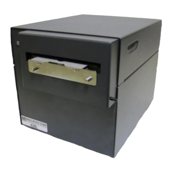
Page 17: Figure 3-1 Typical Printer Accessories
After the printer is removed from the container(s), verify that all the items on the packing list are present and in good condition. The picture below (See Figure 3-1) shows a 428LT, USB cable, and power cord. Your shipment may contain different items. -
Page 18: Figure 3-2 Printer Rear Panel
The printer uses a standard through serial cable, typically referred to as a modem cable, which may be purchased through Microcom Corporation or a local computer supply company. A NULL-modem cable is not required because the printer is configured as DCE. -
Page 19: Table 3-1 Rs-232 Cable Configurations
RS-232 Cable Configurations USB Communication Interface The 428LT printer provides a single USB port for communication to a host device. In order to communicate with the printer, the FTDI USB driver must be installed on the host computer. This may be downloaded at http://www.microcomcorp.com/drivers.htm. The FTDI driver is a CDM driver that provides access to both virtual COM port (VCP) and FTDI’s... - Page 20 1. Open the top cover. 2. Remove the media supply roller. 3. Install the roll of media on the media supply roller. Rotate the Top Cover to the open position Thumbscrew to adjust media guides Figure 3-4 Top Cover 428LT Operator’s Manual - 880040-0200...
-
Page 21: Figure 3-5 Printhead Release
Figure 3-5 Printhead release 5. Loosen the media guide locking thumbscrew and adjust the media guides to your media width. Media Media Guide Guides Thumbscrew Media Low Stock Supply Sensor Roller Figure 3-6 Media Guide Thumbscrew 428LT Operator’s Manual - 880040-0200... -
Page 22: Figure 3-7 Cutter In The Open Position
Cutter in the Open Position 6. Lift up the cutter to release and rotate the cutter assembly to the open position. 7. Insert media between the guides and through the cutter assembly. Figure 3-8 Media Loading 428LT Operator’s Manual - 880040-0200... -
Page 23: Figure 3-10 Printhead Latch
Figure 3-9 Cutter Home Position 9. Close the printhead assembly and verify that it latches on both sides of the assembly. Printhead Assembly Latch Press here to latch printhead. Figure 3-10 Printhead Latch 428LT Operator’s Manual - 880040-0200... -
Page 24: Figure 3-11 Print Button And Status Light
11. Rotate the top cover to the closed position. Paper Low Sensor The Model 428LT provides a sensor to detect paper low conditions. The sensor detects the edge of the roll of media and when the sensor does not detect paper, the printer reports the >INPUT 2<... -
Page 25: Figure 3-12 Paper Low Sensor
Press & hold the Print Button while the printer is IDLE to advance Feeding labels label media. The printer will continue advancing label media until (Line feed) the Print Button is released. Table 3-2 Print Button Description 428LT Operator’s Manual - 880040-0200... -
Page 26: Table 3-3 Status Indicator Light Description
If the printer was just turned ON and no formats were sent to the printer, pressing quickly will print the power-up label, c) Holding the button depressed: Line Feed until the button is released. 3-10 428LT Operator’s Manual - 880040-0200... - Page 27 The printer will use the factory default parameters until the printer has been reset using a soft reset or by cycling power. The printer will then return to the configuration shown on the Status Label. 428LT Operator’s Manual - 880040-0200 3-11...
-
Page 28: Figure 3-13 Status Label (Examples)
STOCK OUT VALUE: 100 STOCK OUT VALUE: 100 PRINTER CODE REV: 02.12.050719A PRINTER CODE REV: 02.12.050719A BOOTLOADER CODE REV: 02.12.050719A BOOTLOADER CODE REV: 02.12.050719A CODE ASSY PN. 071001-0212 CODE ASSY PN. 071001-0212 Figure 3-13 Status Label (Examples) 3-12 428LT Operator’s Manual - 880040-0200... - Page 29 IBM compatible PC and a VT-100 terminal emulation software program. This method of connection will allow two-way, communication with the printer. Items required: A computer with a FTDIUSB driver installed. (Contact your Microcom Corporation representative for more details.) A USB cable with Type-A (host computer) and Type-B (printer) connectors.
- Page 30 “Shift” key and the “6”) plus the alpha character. See Chapter 5 for additional information regarding control codes and printer commands. There are some special features offered by the printer that assist in label design. For example, the auto-size command (^A2^D39 <CR>) provides most of the header format 428LT Operator’s Manual - 880040-0200...
- Page 31 The next line is the header information that sets the label size and other pertinent information. The next five lines are layout and configuration for each data field in the format. 428LT Operator’s Manual - 880040-0200...
-
Page 32: Figure 4-2 3X3 Sample Label
For example, a 4” X 6” label printed with a 300 DPI print head would be 1200 (4 X 300 dots in the horizontal or “X” direction, and 1800 (6 X 300) dots in the “Y” direction. 428LT Operator’s Manual - 880040-0200... - Page 33 HFM parameter, they will be ignored and will not print. The HFM was set to a value of 5 in the format used to create the sample in Figure 4-2. This 428LT Operator’s Manual - 880040-0200...
- Page 34 Generally, better print quality is achieved by printing at lower speeds, however this is also dependent on the media and contrast settings as well. Labels per minute can be calculated by the equation below: IPS x 60 seconds Labels per Minute Label Height 428LT Operator’s Manual - 880040-0200...
- Page 35 When the AGD header parameter is set to “0”, the printer will advance the same amount of media even when text data fields are left blank. In this case, the advance distance is determined by adding the SPG parameter and LSY parameter values. 428LT Operator’s Manual - 880040-0200...
- Page 36 D2G = This is a physical distance from the registration sensor being used to the print head's dot row, and is a specific value for each model; see Table 4-2 LSY = This is the actual height of the media or printable surface in pixels or dots. 428LT Operator’s Manual - 880040-0200...
- Page 37 (Offset Y Direction) HFM, LSX, LSY, WEB, GAP, DPS, LCB, AGD, SPG, OFX, This parameter is used to move or offset all format fields in the Y direction without altering the format fields coordinates themselves. 428LT Operator’s Manual - 880040-0200...
- Page 38 This is a list of the first label format field element mnemonics for the sample label in Figure 4-2: TSN, XB, YB, CC, TCI, CGN, FO, FJ, CMX, CMY, CS, TSP, , , AN 1, 640, 650, 8, 1, , , 0 4-10 428LT Operator’s Manual - 880040-0200...
-
Page 39: Figure 4-4 Label Format Field Elements
Any offsets required for media that is not as wide as the print head must be manually entered for the XB or the OFX header element may be used. 428LT Operator’s Manual - 880040-0200 4-11... - Page 40 Interleaved 2 of 5 Barcode Code 39 Symbol Text with UPC-E Checksum and Extended Bars Added EAN-13 Symbol EAN-8 Symbol Text with EAN-13 Checksum and Extended Bars Added Text with EAN-8 Checksum and Extended Bars Added 4-12 428LT Operator’s Manual - 880040-0200...
- Page 41 The CGN parameter is a numeric entry that determines the representation and size of embedded font and bar codes as well as the memory location of graphic images that have been selected by the TCI parameter. 428LT Operator’s Manual - 880040-0200 4-13...
- Page 42 These fonts are stored in the printer’s non-volatile flash memory and are accessed with a TCI of 7 and the appropriate CGN value. Custom font sets may be loaded into printers at the factory, ask your Microcom Representative for additional information on custom font sets.
- Page 43 Swiss™721 Bold 90 degree Swiss™721 Bold 0 degree Swiss™721 Bold 90 degree Swiss™721 Bold 0 degree Swiss™721 Bold 90 degree OCR-A Normal 0 degree OCR-A Normal 90 degree OCR-B Normal 0 degree OCR-B Normal 90 degree 428LT Operator’s Manual - 880040-0200 4-15...
- Page 44 0123 Maxicode (CGN = Mode) 0123 0123 0123 MSI (Modified Plessey) 0123 Table 4-6 CGN—Bar Code Symbologies * These Symbols must use the CMX or CMY multipliers by 2 to produce an 80% ratio. 4-16 428LT Operator’s Manual - 880040-0200...
- Page 45 90 & 270 Degrees 3 – Right justified below the base-line 4 – Centered on the Y axis, right of X coordinate 5 – Centered on the Y axis, left of the X coordinate 428LT Operator’s Manual - 880040-0200 4-17...
- Page 46 Line Draw function. (Special Note: The AN parameter of the line field should also be set to a “1” for proper reverse imaging.) If the 4-18 428LT Operator’s Manual - 880040-0200...
-
Page 47: Figure 4-5 Line Draw Sample
This is a list of the first label format field element mnemonics for the sample label in Figure 4-5: TSN, XB, YB, CC, TCI, CGN, FO, FJ, CMX, CMY, CS, TSP, , , AN 1, 340, 712, 600, , , , 0 428LT Operator’s Manual - 880040-0200 4-19... -
Page 48: Figure 4-6 Label Format Line Draw
TSN is referencing must contain at least one character in order for a line to print properly. “Line” was used in the example to clearly define the label format fields that contain line values. However, it could have simply been one character such as a period “.” 4-20 428LT Operator’s Manual - 880040-0200... - Page 49 Format Fields defining the line draw and the text fields. The size of the box is not defined by the text. Adjustment to the size of the box must be made by adjusting the line draw coordinates. 428LT Operator’s Manual - 880040-0200 4-21...
-
Page 50: Figure 4-7 Reverse Video Sample
Adjusting the size of the box is surrounding text is limited using this method. It is possible to create a reverse video effect with barcodes using this method. ^D57 5,1280,900,19,38,7,0,1,385,0,0 Microcom 1,640,700,8,1,5,0,4,2,2,,,,,8 2,640,591,11,1,5,0,4,2,2,,,,,8 3,640,443,26,1,5,0,4,,,,,,,8 Corporation 4,640,296,6,1,5,0,4,,,,,,,8 4,640,148,6,16,3,,4,3,75,,,,,0 ^D56 Thermal Printing Solutions Microcom 012345 4-22 428LT Operator’s Manual - 880040-0200... -
Page 51: Figure 4-8 Auto Reverse Video Sample
Chapter 4 Designing Labels with LDS Corporation Thermal Printing Solutions 012345 Figure 4-8 Auto Reverse Video Sample 428LT Operator’s Manual - 880040-0200 4-23... - Page 52 “control B” is shorter, it is easier to use in direct terminal mode. In general it is better to use the ^D2 command sequence inside a file or program to assist in trouble-shooting the format. 428LT Operator’s Manual - 880040-0200...
- Page 53 This command is used to request the printer’s status and is very similar to the ^E command. The biggest difference between this command and the ^E is that when printers are 5-10 428LT Operator’s Manual - 880040-0200...
- Page 54 Text and/or Byte mode rule above but will only Display the Decimal codes. Byte Mode Text Mode Response Definition Response TICKET ACK OUT OF TICKETS ILLEGAL DATA CUTTER JAM Table 5-1 STL Status Responses 428LT Operator’s Manual - 880040-0200 5-11...
- Page 55 This provides a starting point for re-establishing communication with the printer so that user settings may be sent to the printer. The statistics label printed when the printer entered the DEFAULT MODE reflects current printer settings and not the factory default settings. 5-12 428LT Operator’s Manual - 880040-0200...
- Page 56 1 = Enable 0 = Disable Number of Data Bits: Sets the printer’s serial port to use either 7 or 8 data bits. 1 = 8 Data Bits 0 = 7 Data Bits 428LT Operator’s Manual - 880040-0200 5-13...
- Page 57 The printer can be instructed not to load a format at power- up by setting all three switches to 0. 000 = No Power-up Format 001 = ROM or Saved Format File 1 010 = ROM or Saved Format File 2 5-14 428LT Operator’s Manual - 880040-0200...
- Page 58 0 = Enable (<|> key functions as <Ctrl> key) Accept “^” for Ctrl: Sets whether the “caret” character will be interpreted the same as the “Ctrl” key. The “caret” character is the <SHIFT> + 6 key. 1 = Disable 428LT Operator’s Manual - 880040-0200 5-15...
- Page 59 Slashed Zeros: If enabled, the printer will print a slash through the embedded zero (“0”) characters. 1 = Enable 0 = Disable External Print Request: (Call Microcom for more information.) 1 = Enable 0 = Disable Stock Out function: Enable this function to get a >LOW STOCK<...
- Page 60 The correct type of sensor is determined by the printer hardware configuration being used. 1 = TOF is TRANSMISSIVE 0 = TOF is REFLECTIVE 428LT Operator’s Manual - 880040-0200 5-17...
- Page 61 This command provides similar functionality of other printer manufacturers that specify exact placement and location of blackline media used for registration. The printer takes in STL commands and internally converts them to LDS command tables. 5-18 428LT Operator’s Manual - 880040-0200...
- Page 62 /180 degree rotation and in 180/270 degree rotation. The odd memory slots denote 0 or 180 degree rotation fonts while the even memory slots denote 90/270 degree rotated fonts. The flash memory slot locations are shown below: 428LT Operator’s Manual - 880040-0200 5-19...
- Page 63 The CS value used in conjunction with the AN set to a 2 to produce a negative kerning effect should be removed and the field defaulted. This is the 11 field defined in the format lines. 5-20 428LT Operator’s Manual - 880040-0200...
- Page 64 “ERROR INPUT: 0nH” with the value for “n” equaling the HEX value of the inputs. The inputs equal a binary number with the inputs in the following order; 4321. Command Syntax: ^D151<CR>0n<CR> 428LT Operator’s Manual - 880040-0200 5-21...
- Page 65 NOTE: If the printer is not in the general purpose I/O mode, the inputs status may still be read with the ^D150 command but the outputs cannot be read (or written to) with the ^D69 or ^D68 commands. 5-22 428LT Operator’s Manual - 880040-0200...
- Page 66 NOTE: Default power up will disable I/O mode. The P17 and P21 connectors are 8 pin MTA50 AMP part number #1445350-8 and Microcom Corporation part number 510188-0008. The pin out is as follows (the square pad denotes pin one on the PCB): Connector P17 is the input port.
- Page 67 These bits are used to select the width of the stock (in inches) to be used according to the following bit pattern: 000 – 1.00 100 – 1.328 010 – 2 110 – 2.125 001 – 2.5 101 – 2.75 5-24 428LT Operator’s Manual - 880040-0200...
- Page 68 (when sw6 p4 set) just sw8 p7 must be set (since there may not be a valid LCB in play). 1 = Disable system parameter saving 0 = Enable system parameter saving NOT USED: 428LT Operator’s Manual - 880040-0200 5-25...
- Page 69 AutoSelect: When the printer powers up, it scans the USB and RS-232 ports and selects the “Active” port. The USB port will be selected if the USB cable is connected between the printer and a PC that is powered “ON.” The RS-232 5-26 428LT Operator’s Manual - 880040-0200...
- Page 70 The Ethernet port is generally a third party device that provides the printer with the connectivity of an Ethernet system. Internally, the signals go into a serial port. The Ethernet is setup and configured separated from the 428LT Operator’s Manual - 880040-0200 5-27...
- Page 71 PCB, to change the status of the outputs, and to configure the inputs to generate immediate errors. Command General Purpose Status Byte The printer has a special mode of communication for General Purpose control environments. Communication is over the Ethernet port and uses the following protocol. 5-28 428LT Operator’s Manual - 880040-0200...
- Page 72 NO FORMAT LOADED not used not used not used 7 (MSB) not used The General Purpose Status byte mode of operation is enabled by Soft Switch #5, Bit #8. These are the specific commands: 428LT Operator’s Manual - 880040-0200 5-29...
- Page 73 Send the printer a ^D116<CR> command. This will force the printer to process the label to the point that the label bitmap is ready to be sent to the print head. After this command is sent 5-30 428LT Operator’s Manual - 880040-0200...
- Page 74 COMMAND Adjust Contrast Window: This is a volatile command used to adjust the contrast window. The range is 1 to 9 of the base (^D36). 428LT Operator’s Manual - 880040-0200 5-31...
- Page 75 The printer will update and write the configuration to flash on normal power downs. This command may be used to start using certain non-volatile system parameters (head parameter and soft switch commands). 5-32 428LT Operator’s Manual - 880040-0200...
- Page 76 COMMAND Auto-size: Clears the use of auto-size values set by issuing the ^A1^D39<CR>. 428LT Operator’s Manual - 880040-0200 5-33...
- Page 77 This command is a specialty media handling command that works when the correct media is used. Please contact your Microcom Corporation representative if you have any questions regarding the use of this command. When enabled the printer will autoload...
- Page 78 These are the steps for AutoLoad + FF: 1. With the head mechanism latched in its normal print position, the user inserts new media until it stops at the drive roller. 428LT Operator’s Manual - 880040-0200 5-35...
- Page 79 Soft switch #5, bit #3 selects the type of TOF sensor. The TOF may a REFLECTIVE style, or it may use a TRANSMISSIVE sensor for more accurate sensing. These are the steps for AutoLoad with TOF: 5-36 428LT Operator’s Manual - 880040-0200...
- Page 80 Media is advanced until the leading edge is detected by the reflective “Top Of Form” sensor, b) Media is retracted to place the leading edge of stock under the print head. This command is useful when using the AutoLoad + Top of Form command. 428LT Operator’s Manual - 880040-0200 5-37...
- Page 81 “^Axx” sequence just like the ^D73 command. This command may also be used in conjunction with the ^D73 command. The batch of labels is printed once a ^D3 command is executed; therefore the ^D75 command must be 5-38 428LT Operator’s Manual - 880040-0200...
- Page 82 Please note that the ^D57 command clears most of the serial number commands. Therefore, all serial number commands should be placed after the ^D56 command or just prior to the ^D3 command. 428LT Operator’s Manual - 880040-0200 5-39...
- Page 83 Load Field Number to Decrement by 1: The ^Axx specifies which text string field that will be decremented by one. The printer will not decrement fields beyond 0. Fields that instructs the printer to decrement beyond 0 will be set to 5-40 428LT Operator’s Manual - 880040-0200...
- Page 84 If set to a value of 2, the first line of new text entered following the ^D2 will overwrite line two. If two new text strings are entered, the existing text lines two and three will be overwritten. This command is used 428LT Operator’s Manual - 880040-0200 5-41...
- Page 85 The printer may be programmed to enter the mode automatically upon power-up by position 1 of software switch #2 (^D22 command). Enable modes 1 and 2. 5-42 428LT Operator’s Manual - 880040-0200...
- Page 86 This value is reported to the ^D29 statistics label. This command should be used prior to enabling the cutter with the ^D99 or ^D111 commands. Command Set Cutter Type No Cutter Guillotine Rotary 428LT Operator’s Manual - 880040-0200 5-43...
- Page 87 (dot row one). The ^D99 command will assume a default ^D95 value of 155. Recommend distance for a 203dpi 428LT is 189 while a 300dpi 428LT would be 280.
- Page 88 Partial Cut Mode (^D99), but not the Kiosk Cut Mode. This function will skip a pre-set number of cuts following a Top of Form. Count resets and begins count at TOF or following the point where the command is given. 428LT Operator’s Manual - 880040-0200 5-45...
- Page 89 This may create a paper jam when the label is retracted back into the printer. Load Advance Delay: The ^Axx specifies the amount time, in milliseconds, 5-46 428LT Operator’s Manual - 880040-0200...
- Page 90 Process Format Saved in RAM: The ^Axx selects which stored format to process (1-128). This command is processed in the same was as if the format was sent directly to the port. 428LT Operator’s Manual - 880040-0200 5-47...
- Page 91 This command supports fonts greater than 64KB. Delete Graphics from RAM ^A0 deletes ALL graphics from RAM. ^Ax deletes the graphics in slot #x. xxyy 107 Save Compressed GRAPHICS to RAM. (See Chapter 6, Downloadable Graphics) 5-48 428LT Operator’s Manual - 880040-0200...
- Page 92 1) Create the FORMAT file with ^Axx^D130 at the top to tell the printer to store into FLASH Slot #xx. 2) Send the file to the printer using a standard communications program. Sample format saved to RAM slot #1: ^A1^D130 ^D57 5,1280,900,19,38,7,0,1,385,0,0 428LT Operator’s Manual - 880040-0200 5-49...
- Page 93 FONT download for FLASH memory is coming. The download will be 2 sectors long, and the printer will access the FONT in FLASH memory using CGN #24 and TCI #7. The ^A0124^D135 command will be right at the 5-50 428LT Operator’s Manual - 880040-0200...
- Page 94 Hint: After the FONT file has been deleted, the ^D119 command may be used to verify that Slot #xx is now available in RAM. The FONT may extend over several slots and the ^D119 will indicate how many slots are used. 428LT Operator’s Manual - 880040-0200 5-51...
- Page 95 This command is equivalent to sending: ^A0^D134 (clears all GRAPHICS), ^A0^D137 (clears all FONTS). Label FORMATS stored in user FLASH memory are NOT erased by this command. Use the ^D131 command to erase label FORMATS stored in FLASH memory. 5-52 428LT Operator’s Manual - 880040-0200...
- Page 96 ^A62519^D7 command will update the printer’s bootloader, application, and embedded font set. This process requires some interactivity with the printer and failure to follow the proper process will cause the printer to become inoperable. Please contact your Microcom Corporation Representative for more information. 5.14...
- Page 97 2. The Host then sends the printer the ^D149 command followed by the raw image size that has been converted by the bmp2mic rev 1.02 or later. Please note that the size is only terminated with a [CR] and the [LF] is not included. Example: ^D149[CR][LF]size[CR] 5-54 428LT Operator’s Manual - 880040-0200...
- Page 98 Feed Reverse Distance: This command will move the motor in the reverse direction by the X amount (specified in dots) when issued. The maximum value is 65535. The feed speed is defined by the D155 command. 428LT Operator’s Manual - 880040-0200 5-55...
- Page 99 2 to 65536. This command is volatile and gets reset to the default setting after power cycles and/or command reset conditions. The ^A1^D145 command may be used to observe the current setting and the elapsed time counter. 5-56 428LT Operator’s Manual - 880040-0200...
- Page 100 The Dot2gap distances represent the physical characteristics of the printer models. This command is used in conjunction with the Finish Mode feature; see the D27 command bit position 8 for more information. 428LT Operator’s Manual - 880040-0200 5-57...
- Page 101 After a power up, reports the “running” total of detected Brownouts. Clears the “running” total or volatile brownout count Reports the non-volatile brownout count stored in memory Clears the non-volatile brownout count stored in memory 5-58 428LT Operator’s Manual - 880040-0200...
- Page 102 Create a name for the converted GRAPHIC File. (Limit the file name to 8 characters. An extension is not necessary.) 3) Out Type See Section 6.4. 4) Slot Number Select an open slot number for storage. Use ^D119 to determine which slots are open. 428LT Operator’s Manual - 880040-0200...
- Page 103 Press [ENTER] C:\>BMP2MIC.exe 2. Type the conversion utility name and required information at the command prompt. Press [ENTER]. BMP2MIC - Convert BMP Graphic File to Microcom Printer Graphic Rev. 2.01 Copyright 1998-2005 Microcom Corp., Westerville, Ohio Use: BMP2MIC <infile> <outfile> <outtype> <slotnum> <limit> <destination>...
- Page 104 6.5 Advanced GRAPHIC Format Conversion for Programmers The following sections are provided to developers who wish to create usable GRAPHIC images within their own applications. Commands in the following section are not typically seen for users using Microcom GRAPHIC utilities. 428LT Operator’s Manual - 880040-0200...
- Page 105 GRAPHIC uses, not the number of bytes that will actually be transmitted. Due to compression, the number of bytes transmitted will normally be less than this number. <Image Data> is the compressed binary image. 428LT Operator’s Manual - 880040-0200...
- Page 106 (4 X 256)+1+107 = 1132 6.5.4 Uncompressed FONT to RAM (^D104) This command allows graphic and/or font images (fonts must be less than 64KB uncompressed) to be transmitted in ASCII-HEX, thereby allowing all data to pass over 7 or 428LT Operator’s Manual - 880040-0200...
-
Page 107: Figure 6-1 Ascii-Hex Conversions
All data is stored in binary form. Multi-byte values are stored least-significant-byte first. The method illustrated below allows graphic images to span 64KB memory segments. When using graphics over 64KB, the printer will determine the number of 64KB slots 428LT Operator’s Manual - 880040-0200... - Page 108 2d array. The most significant bit of the first byte in each row, prints as the right most dot of the character, and the first row is the bottom row when printed. 428LT Operator’s Manual - 880040-0200...
- Page 109 Deletes the graphics in slot #XX Save GRAPHICs or FONTs into RAM Memory without Compression: This command is intended for legacy support only and Microcom Corporation recommends either the ^D104 or ^D107 commands. Fonts must be less than 64KB for this command to function.
- Page 110 TCI must be set to an “8” for volatile downloadable fonts and the CGN refers to the memory slot location of the downloaded font. Nonvolatile fonts are accessed thru TCI “7”. 428LT Operator’s Manual - 880040-0200...
- Page 111 7-bit data connections. The uncompressed (^D104) is usable on either 7 or 8-bit connections and is more flexible but encodes using ASCII-HEX. This results in a much larger file size. Microcom Corporation recommends the use of the compressed format when possible.
- Page 112 This command allows graphic and/or font images (fonts must be less than 64KB uncompressed) to be transmitted in ASCII-HEX, thereby allowing all data to pass over 7 or 8-bit data connections. This command is usable on data connections that support either 7 or 8-bit data. 428LT Operator’s Manual - 880040-0200...
- Page 113 FONT download for FLASH memory is coming. The download will be 2 sectors long, and the printer will access the FONT in FLASH memory using CGN #24 and TCI #7. The ^A0124^D135 command will be right at the 428LT Operator’s Manual - 880040-0200...
- Page 114 All data is stored in binary form. Multi-byte values are stored “least significant byte” first. The printer can store a font of approximately 64KB or less in any one memory slot location. 428LT Operator’s Manual - 880040-0200...
- Page 115 2d array. The most significant bit of the first byte in each row, prints as the right most dot of the character, and the first row is the bottom row when printed. 428LT Operator’s Manual - 880040-0200...
- Page 116 80 HEX. This command supports GRAPHICS over 64KB. Load GRAPHIC or FONT into RAM Memory without Compression: This command is intended for legacy support only and Microcom Corporation recommends either the ^D104 or ^D107 commands. Fonts must be less than 64KB for this command to function.
- Page 117 Downloadable Fonts Chapter 7 428LT Operator’s Manual - 880040-0200...
- Page 118 UPC-E bar codes do not use inter-character spacing, therefore the character spacing (CS) element must be defaulted. The chart listed in Table 14 illustrates how the 11 digits are reduced to only 6 using the “zero suppression” compression. 428LT Operator’s Manual - 880040-0200...
-
Page 119: Table 8-1 Upc-E Zero Reduction Format
(“*”) character, which is reserved for this purpose. This symbology uses 2:1, 3:1, 4:2, 5:2, and 8:3 ratios, which may be selected using the CGN parameter. Although most specifications require a specific inter-character 428LT Operator’s Manual - 880040-0200... - Page 120 Postnet is a numeric-only symbology that is commonly used in postal application to sort mail. The five-digit zip or five-digit zip plus four-digit extension may be used to generate this Postnet (TCI 36) bar code. Example: 12345 or 12345-1234. 428LT Operator’s Manual - 880040-0200...
- Page 121 Total Number - Total number of barcodes in the series. Country Code - Three digits. Service Code - Three digits. Zip Code - 9 digits The data string associated with a MaxiCode field shall be formatted according to the Mode selected (2-6). 428LT Operator’s Manual - 880040-0200...
- Page 122 Table 15, and occupy only one character in the encoded string. Mode 5 Mode 5 may encode any string of up to 77 characters. Control characters are specified in Table 15, and occupy only one character in the encoded string. 428LT Operator’s Manual - 880040-0200...
- Page 123 Code 128 (Automatic Compression), TCI 40 The Code 128 bar code is a variable length, high density, alphanumeric symbology that is extensively used worldwide. This bar code uses three subsets (A, B, and C) which allows 428LT Operator’s Manual - 880040-0200...
-
Page 124: Figure 8-1 Code 128 Subset Switching
C the user must send the appropriate code (#n) to return to either subset A or B. ABC#3012345#5abc The “#5” code, while printer in subset C, switches The “#3” code, while in defaults to to subset A. subset B, switches to subset B subset C. Figure 8-1 Code 128 Subset Switching 428LT Operator’s Manual - 880040-0200... - Page 125 The following format is used to generate a PDF-417 bar code: ^D77<CR> :Text Data^\ Number_of_Rows<CR> Number_of_Columns<CR> Rotation<CR> ECC_Percent<CR> 428LT Operator’s Manual - 880040-0200...
- Page 126 This parameter is used to adjust the aspect ratio of the PDF-417 symbology. The value is entered in ratio format (height: width) and has a default value of 2:1. A carriage return character must be used to terminate this field. 428LT Operator’s Manual - 880040-0200...
-
Page 127: Figure 8-2 Pdf-417 Sample Format #1
The following format samples show how to generate a PDF-417 bar code: Sample Format #1: ^D77<CR> :PDF-417 bar code data^[ 3<CR> 30<CR> 0<CR> 0<CR> 0<CR> 2:1<CR> ^D57<CR> 2,575,609,,25,35,0,1,285<CR> Text string 1,190,300,1,46<CR> 2,190,200,11,1,5<CR> ^D56<CR> ^D2<CR> P<CR> Text string<CR> ^D3<CR> Figure 8-2 PDF-417 Sample Format #1 8-10 428LT Operator’s Manual - 880040-0200... -
Page 128: Figure 8-3 Pdf-417 Sample Format #2
< Rotation - set to 1 = 180 deg > < use Ascii encoding > 0123456789 < data to encode > ^D57 < LDS1 Format > 2,1280,900,,,10,0,1,250 1,300,300,1,47,,,,10,10 < See Multiplier note below > 2,300,230,11,1,5 ^D56 Data Matrix 428LT Operator’s Manual - 880040-0200 8-11... - Page 129 Numeric Alphanumeric Binary Byte Symbol Size Capacity Capacity Capacity Auto 10 x 10 12 x 12 14 x 14 16 x 16 18 x 18 20 x 20 22 x 22 24 x 24 8-12 428LT Operator’s Manual - 880040-0200...
- Page 130 The printer default is set to “Auto”, which will automatically switch to the most efficient encoding scheme for the data provided. Refer to the table below for the valid choices for the encoding parameter. 428LT Operator’s Manual - 880040-0200 8-13...
-
Page 131: Table 8-6 Data Matrix Encoding Schemes
X12 Encoding Scheme X12 encoding scheme is use to encode the standard ANSI X12 electronic data interchange characters, which are compacted three data characters to two codewords in a manner similar to C40 encoding. 8-14 428LT Operator’s Manual - 880040-0200... -
Page 132: Table 8-7 Ascii Codeword Values
Latch to C40 Encoding Scheme Latch to Base256 Encoding Scheme FNC1 Structured Append Reader Programming Upper Shift (shift to Extended ASCII) 05 Macro 06 Macro Latch to Text Encoding Scheme ECI Character Table 8-7 ASCII Codeword Values 428LT Operator’s Manual - 880040-0200 8-15... -
Page 133: Figure 8-4 4-State Barcode Bars
(“-“) character. The “-“ character may be included to separate the tracking code from the routing code but the maximum number a characters contained within the barcode is 31 with the structure being outlined below: 8-16 428LT Operator’s Manual - 880040-0200... - Page 134 < Rotation > 53379777234994544928-51135759461 < 4-State Data> ^D57 4,1280,800,0,38,08,0,1,418,0,0 1,100,400,1,48,,,4,6,15 < 4-State Placement Field> 2,550,600,16,1,5,,4 4,550,300,33,1,5,,4 3,550,500,12,1,5,,4 ^D56 < 4-State Text Placeholder; can be anything> Intelligent Mail Test Case #1 53379777234994544928-51135759461 Figure 8-5 4-State Barcode Structure 428LT Operator’s Manual - 880040-0200 8-17...
- Page 135 Data strings can contain one or more substrings appended onto one line. Each substring can consist of a 2, 3 or 4 digit Application Identifier immediately followed by a data string meeting the formatting requirements for that specific Application Identifier. 8-18 428LT Operator’s Manual - 880040-0200...
- Page 136 Dimension, Meters n4+n6 312(***) Width Diameter, or 2 Dimension, Meters n4+n6 313(***) Depth Thickness, Height or 3 Dimension, Meters n4+n6 314(***) Area, Square Meters n4+n6 315(***) Volume, Liters n4+n6 316(***) Volume, Cubic Meters n4+n6 428LT Operator’s Manual - 880040-0200 8-19...
- Page 137 Depth Thickness, Height or 3 Dimension, Yards, 349(***) n4+n6 Logistics 350(***) Area, Square Inches n4+n6 351(***) Area, Square Feet n4+n6 352(***) Area, Square Yards n4+n6 353(***) Area, Square Inches, Logistics n4+n6 354(***) Area, Square Feet, Logistics n4+n6 8-20 428LT Operator’s Manual - 880040-0200...
- Page 138 Offer, and End of Offer Coupon Extended Code – Number System Character 8102 n4+n1+n1 preceded by zero Mutually Agreed, Between Trading Partners or FACT n2+an..30 Intra-Company (Internal) n2+an..30 Intra-Company (Internal) n2+an..30 Intra-Company (Internal) n2+an..30 428LT Operator’s Manual - 880040-0200 8-21...
-
Page 139: Table 8-8 Ucc/Ean Application Identifiers
All six different RSS-14 symbologies: 1) RSS-14 2) RSS-14 Truncated 3) RSS-14 Stacked 4) RSS-14 Stacked Omni-directional 5) RSS-14 Limited 6) RSS-14 Expanded. 8-22 428LT Operator’s Manual - 880040-0200... - Page 140 The barcode contains a separator pattern, containing no data, which has a height equal to one X dimension. This symbology can not be scanned omni-directionally. This symbology does not allow for human readable test with the barcode. Figure 8-8 RSS-14 Stacked Sample 428LT Operator’s Manual - 880040-0200 8-23...
- Page 141 How to Print an RSS-14 Barcode There are two steps to printing an RSS-14 barcode: 1) Send the ^D114 command and the 7 setup parameters 2) Send a label format that calls the RSS-14 barcode TCI #35. 8-24 428LT Operator’s Manual - 880040-0200...
- Page 142 ß Use standard RSS-14 symbol 0<CR> ß Multiply size by 5 5<CR> ß Use 22 segments/row 22<CR> ß X undercut = 0 0<CR> ß Y undercut = 0 0<CR> ß Set vertical separator = 5 5<CR> 428LT Operator’s Manual - 880040-0200 8-25...
- Page 143 Rotated Bar Code Program Sample, see Figure 26: ^D57<CR> 5,575,609,,25,35,0,1,285,0,0 <CR> 1,300,500,5,16,2,0,,2,100<CR> 1,300,400,5,16,2,1,,2,100<CR> 1,300,300,5,16,2,2,,100,2<CR> 1,300,300,5,16,2,3,,100,100<CR> 2,288,300,9,1,5,0,4<CR> ^D56 <CR> ^D2 <CR> 12345<CR> ROTATIONS<CR> ^D3<CR> 8-26 428LT Operator’s Manual - 880040-0200...
- Page 144 Text with MSI 1 Checksum added Text with MSI 2 Checksum added Text with UPC-A Checksum and Extended Bars added Text with UPC-A with Extended Bars added EAN128 Table 8-9 Human Readable/Extended Bars TCI’s 428LT Operator’s Manual - 880040-0200 8-27...
- Page 145 Sample Format: ^D57<CR> 4,575,609,,25,35,0,1,285,0,0<CR> 1,200,418,11,12,,,,2,50<CR> 1,178,400,11,32,,,,2,2<CR> 1,200,150,11,12,,,,2,50<CR> 1,178,125,11,32,,,,2,2<CR> ^D56<CR> ^D2<CR> 01234567890<CR> ^D3<CR> 8-28 428LT Operator’s Manual - 880040-0200...
- Page 146 2. Code Page 850 3. Code Page 852 4. Code Page 860 5. Code Page 863 6. Code Page 865 7. USA 8. British 9. German 10. French 11. Italian 12. Danish 13. Spanish 14. Swedish 15. Swiss 428LT Operator’s Manual - 880040-0200...
-
Page 147: Figure 9-1 Code Page - Default
Code Switching Chapter 9 9.3.1 Code Pages The Default Code Page is selected when SW4:(5-8) = 0000. Figure 9-1 Code Page - Default 428LT Operator’s Manual - 880040-0200... -
Page 148: Figure 9-2 Code Page - Danish
Chapter 9 Code Page Switching 9.3.2 Danish Code Page The Danish Code Page is selected when SW4:(5-8) = 0001. Refer to Section 5.1.2.4 for more details on SW4 settings. Figure 9-2 Code Page - Danish 428LT Operator’s Manual - 880040-0200... - Page 149 Code Switching Chapter 9 9.3.3 860 Code Page The 860 Code Page is selected when SW4:(5-8) = 0010 This code page is also known as DOS Portuguese. Figure 9-3 Code Page - 860 428LT Operator’s Manual - 880040-0200...
-
Page 150: Figure 9-4 Code Page - Spanish
Albanian, Rhaeto-Romanic, Dutch, German, Danish, Swedish, Norwegian, Finnish, Faroese, Icelandic, Irish, Scottish, and English. It covers the entire North American continent, Australia, and much of Africa. Refer to Section 5.1.2.4 for more details on SW4 settings. 428LT Operator’s Manual - 880040-0200... - Page 151 Code Switching Chapter 9 Figure 9-5 Code Page - 850 428LT Operator’s Manual - 880040-0200...
-
Page 152: Figure 9-6 Code Page - German
Chapter 9 Code Page Switching 9.3.6 German Code Page The German Code Page is selected when SW4:(5-8) = 0101. Refer to Section 5.1.2.4 for more details on SW4 settings. Figure 9-6 Code Page - German 428LT Operator’s Manual - 880040-0200... - Page 153 Code Switching Chapter 9 9.3.7 865 Code Page The 865 Code Page is selected when SW4:(5-8) = 0110 This code page is also known as DOS Nordic. Figure 9-7 Code Page - 865 428LT Operator’s Manual - 880040-0200...
-
Page 154: Figure 9-8 Code Page - Swiss
The 852 Code Page is selected when SW4:(5-8) = 1000. This code page is also known as DOSLatin2 (Eastern Europe). Latin2 covers the languages of Central and Eastern Europe: Czech, Hungarian, Polish, Romanian, Croatian, Slovak, Slovenian, and Sorbian. 428LT Operator’s Manual - 880040-0200... - Page 155 Code Switching Chapter 9 Figure 9-9 Code Page - 852 9-10 428LT Operator’s Manual - 880040-0200...
-
Page 156: Figure 9-10 Code Page - French
Chapter 9 Code Page Switching 9.3.10 French Code Page The French Code Page is selected when SW4:(5-8) = 1001. Refer to Section 5.1.2.4 for more details on SW4 settings. Figure 9-10 Code Page - French 428LT Operator’s Manual - 880040-0200 9-11... - Page 157 Code Switching Chapter 9 9.3.11 863 Code Page The 863 Code Page is selected when SW4:(5-8) = 1010 This code page is also known as DOS French Canada. Figure 9-11 Code Page - 863 9-12 428LT Operator’s Manual - 880040-0200...
-
Page 158: Figure 9-12 Code Page - Swedish
Code Page 437 is the famous code page used in the original IBM PC. This code page contains lot of box drawing characters and a few foreign letters. The 437 Code Page is selected when SW4:(5-8) = 1100. This code page is also known as DOS Latin US. 428LT Operator’s Manual - 880040-0200 9-13... - Page 159 Code Switching Chapter 9 Figure 9-13 Code Page - 437 9-14 428LT Operator’s Manual - 880040-0200...
-
Page 160: Figure 9-14 Code Page - Italian
Chapter 9 Code Page Switching 9.3.14 Italian Code Page The Italian Code Page is selected when SW4:(5-8) = 1101 Refer to Section 5.1.2.4 for more details on SW4 settings. Figure 9-14 Code Page - Italian 428LT Operator’s Manual - 880040-0200 9-15... -
Page 161: Figure 9-15 Code Page - British
Code Switching Chapter 9 9.3.15 British Code Page The British Code Page is selected when SW4:(5-8) = 1110. Refer to Section 5.1.2.4 for more details on SW4 settings. Figure 9-15 Code Page - British 9-16 428LT Operator’s Manual - 880040-0200... -
Page 162: Figure 9-16 Code Page - Usa
Chapter 9 Code Page Switching 9.3.16 USA Code Page The USA Code Page is selected when SW4:(5-8) = 1111. Refer to Section 5.1.2.4 for more details on SW4 settings. Figure 9-16 Code Page – USA 428LT Operator’s Manual - 880040-0200 9-17... - Page 163 Code Switching Chapter 9 9-18 428LT Operator’s Manual - 880040-0200...
-
Page 164: Table 10-1 Recommended Maintenance Schedule
It is important to note that the optimum print quality and print head life is achieved by maintaining a clean printer and print head. A Microcom Corporation approved cleaning kit (part # 040005-0000) is available; contact your sales representative for purchasing information. -
Page 165: Figure 10-1 Inserting Cleaning Card
Any decline in print quality, voids or dropout areas in bar codes and/or graphics may indicate that the print head is dirty and needs to be cleaned. The necessary cleaning materials may be purchased through Microcom Corporation by contacting your sales representative and ordering the Cleaning Kit, part # 040005-0000. Also, ask your Sales Representative about Thermal cleaning pens or the many types of pre-moistened cleaning swabs available. -
Page 166: Figure 10-2 Internal Cleaning
Please note that individually pre- moistened cleaning swabs or Thermal Cleaning pens are available as well. Clean the Media Path Clean the Platen Roller Clean the Cutter Blades Figure 10-2 Internal Cleaning 428LT Operator’s Manual - 880040-0200 10-3... -
Page 167: Figure 10-3 Cleaning The Print Head
Figure 10-3 Cleaning the Print Head CAUTION: Isopropyl Alcohol should be used to clean the drive roller. The use of other cleaning solvents or materials is not recommended and may degrade the performance of the drive roller. 10-4 428LT Operator’s Manual- 880040-0200... -
Page 168: Figure 10-4 Removing The Media Exit Chute
Using a cotton swab dampened with Isopropyl Alcohol to remove any adhesive buildup from the upper cutter blade. Small tweezers may also be used to remove excessive adhesive build up as well. 428LT Operator’s Manual - 880040-0200 10-5... -
Page 169: Figure 10-5 Cleaning The Upper Cutter Blade
6. Continue to rotate the blades until the lower cutter blade is fully exposed. Using a cotton swab dampened with Isopropyl Alcohol to remove any adhesive buildup from the lower cutter blade. Small tweezers may also be used to remove excessive adhesive build up as needed. 10-6 428LT Operator’s Manual- 880040-0200... -
Page 170: Figure 10-6 Cutter Rotation Knob
Once the know is pressed in, rotate the wheel to expose the lower cutter blade Figure 10-6 Cutter Rotation Knob Lower Cutter Blade Figure 10-7 Cleaning the Lower Cutter Blades 428LT Operator’s Manual - 880040-0200 10-7... -
Page 171: Figure 10-8 Removing Adhesive With Tweezers
Printer Maintenance Chapter 10 Figure 10-8 Removing adhesive with Tweezers 7. After finished inspecting and cleaning the cutter blades, turning the printer back on will automatically home the cutter blades to its normal operating position. 10-8 428LT Operator’s Manual- 880040-0200... - Page 172 ü Press the print button; light should turn green and resume printing if the printer has been paused. ü Remove the tag, the light should turn green if a tag/tear mode is enabled ü Contact your Service Representative. 428LT Operator’s Manual - 880040-0200 11-1...
- Page 173 ü The intended memory slot is already occupied. ü Verify that the printer is properly configured for the type of download being sent. ü Clear memory and attempt download again. ü Verify that the format has been created properly. 11-2 428LT Operator’s Manual - 880040-0200...
- Page 174 ^D26 Software Switch #6 ......................5-18, 5-24, 5-25 ^D29 Printer Statistics .......................... 5-47, 12-9 ^D3 Print Command ..........................5-38, 12-6 ^D32 Reset Printer ..........................5-32, 12-9 ^D33 Display Model and Revision Number ..................5-47, 12-9 428LT Operator’s Manual - 880040-0200 13-1...
- Page 175 ^D97 Tag/Tear Dispense Mode ......................5-46, 12-13 ^D98 Peel-n-Dispense Mode ......................5-46, 12-13 ^D99 Cutter Control ..........................5-44, 12-14 Agency Approvals .............................. Alphanumeric ..............................12-21 Application Identifiers..........................8-19, 8-22 ASCII Graphic or FONT to RAM (^D104) ......................7-3 13-2 428LT Operator’s Manual - 880040-0200...
- Page 176 Conversion Utilities ............................7-2 CTS ................................12-21 Cutter ................................12-21 Data Bits ................................Data Matrix Symbol ......................8-11, 8-12, 8-13, 8-14 DCD ................................12-21 DCE ................................12-21 Die-cut media ..............................12-21 Direct Thermal ............................... 12-21 428LT Operator’s Manual - 880040-0200...
- Page 177 HFM ............................4-5, 5-39, 12-10 LCB ............................ 4-7, 4-8, 5-39, 12-10 LSX ................................4-6 LSY ..........................4-6, 4-7, 4-8, 5-39, 12-10 OFX ............................4-9, 5-39, 12-10 OFY ............................4-9, 5-39, 12-10 SPG ........................... 4-7, 4-8, 5-39, 12-10 13-4 428LT Operator’s Manual - 880040-0200...
- Page 178 Printing ................................ 5-38 Serial Numbers ............................5-39 Text String ............................5-27, 5-41 Printer Depth ..............................Printer Enquires ............................... 5-11 Printer Height ..............................Printer Weight ..............................Printer Width ..............................Printhead ............................12-21, 12-23 Return Material Authorization .......................... 12-3 428LT Operator’s Manual - 880040-0200...
- Page 179 Tag stock ............................... 12-23 Temperature ..............................Thermal Printer Card ............................10-2 Troubleshooting ............................... 11-1 TXD ................................12-23 Unpacking ................................3-1 UPC-A Symbol ..............................8-1 UPC-E Symbol ............................. 8-1, 8-2, 8-3 USB................................12-23 Warranty ................................12-1 13-6 428LT Operator’s Manual - 880040-0200...
-
Page 180: Table Of Contents
Figure 8-5 4-State Barcode Structure ..............8-17 Figure 8-4 RSS-14 Standard Sample ..............8-23 Figure 8-5 RSS-14 Truncated Sample ..............8-23 Figure 8-6 RSS-14 Stacked Sample ..............8-23 Figure 8-7 RSS-14 Stacked Omni-directional Sample ......... 8-24 428LT Operator’s Manual - 880040-0200... - Page 181 Figure 10-4 Removing the media exit chute ............10-5 Figure 10-5 Cleaning the Upper Cutter Blade ............10-6 Figure 10-6 Cutter Rotation Knob ................. 10-7 Figure 10-7 Cleaning the Lower Cutter Blades ............. 10-7 Figure 10-8 Removing adhesive with Tweezers ........... 10-8 13-8 428LT Operator’s Manual - 880040-0200...
- Page 182 Data Matrix Configuration Parameters ..........8-13 Table 8-6 Data Matrix Encoding Schemes ............8-14 Table 8-7 ASCII Codeword Values..............8-15 Table 8-8 UCC/EAN Application Identifiers ............8-22 Table 8-9 Human Readable/Extended Bars TCI’s..........8-27 Table 10-1 Recommended Maintenance Schedule..........10-1 428LT Operator’s Manual - 880040-0200...
- Page 183 13-10 428LT Operator’s Manual - 880040-0200...
- Page 184 Although the user is not required to purchase Microcom Corporation brand supplies, to the extent it is determined that the use of other supplies (such as non-approved label stock, ribbons, and cleaning solutions) shall have caused any defects in the thermal print head for which the warranty claim has been made, the user shall be responsible for Microcom Corporation’s...
- Page 185 12-2 428LT Operator’s Manual - 880040-0200...
- Page 186 Return the defective item(s) for repair to the address listed above, freight and insurance prepaid. Upon receipt of an RMA number, the customer contact will be notified by a Microcom Corporation representative regarding repair charges, at which time the ship method will be determined.
- Page 187 12-4 428LT Operator’s Manual - 880040-0200...
- Page 188 SW3 bit 7) mode. This is helpful when placed just before a graphic file. The printer will continue processing the data as binary data until instructed to exit the temporary binary mode (5 NULL’s +0F). 428LT Operator’s Manual - 880040-0200 12-5...
- Page 189 9600 bps 19200 bps 38400 bps 57600 bps 115200 bps 230400 bps (only used for D149 Image Mode) 460800 bps (only used for D149 Image Mode) 921600 bps (only used for D149 Image Mode) 12-6 428LT Operator’s Manual - 880040-0200...
- Page 190 1 = Disable use of | for control; 0 = Enable 1 = Disable use of ^ for control; 0 = Enable 1 = Enable Binary Compression; 0 = Disable 1 = Enable Detect Blackline on Power-up; 0 = Disable 428LT Operator’s Manual - 880040-0200 12-7...
- Page 191 1 = Button is TOF; 0 = Button is Defined by SW#2 bit4 1 = Enable AutoLoad; 0 = Disable 1 = AutoLoad+TOF; 0 = Autoload+FF 1 = Enable Status Byte Mode; 0 = Disable 12-8 428LT Operator’s Manual - 880040-0200...
- Page 192 Clear the Printed Inches variable in the statistics. Restart Printer: Restores the printer to power-up settings. Also used to set the non-volatile fields in memory. Display Model and Revision Number Adjust Contrast Window: This is the temporary contrast adjustment. The 428LT Operator’s Manual - 880040-0200 12-9...
- Page 193 RAM. Valid values for Axx are A1 to A128. Select Default Power-up Format: Selects the ROM power-up format. The ^Axx selects from the available formats 1 through 8. Select User Defined Layout: Signals the end of the label field definition. 12-10 428LT Operator’s Manual - 880040-0200...
- Page 194 Load Label Count: Instructs the printer to print a batch of labels using the serial number functions if enabled. Load Delay Time Between Labels: The ^Axx specifies the delay time in 1/10ths of a second. Maximum value is 650. Load PDF-417 Bar Code Data 428LT Operator’s Manual - 880040-0200 12-11...
- Page 195 Reflective Detection Sensitivity: The ^Axx value sets the point (0-255) at which the printer detects a blackline registration mark using the reflective sensor. The printer’s threshold default is a value of 100 for the reflective 12-12 428LT Operator’s Manual - 880040-0200...
- Page 196 Milliseconds, the printer waits before retracting to dot row in cutter and dispense modes. Tag/Tear Dispense Mode: Disables Tag/Tear Mode Advance after every label. Advance after copies count. Advance when idle. Peel-n-Dispense Mode: Disable Peel-n-Dispense Enable Peel-n-Dispense 428LT Operator’s Manual - 880040-0200 12-13...
- Page 197 1-255 Value of X deletes the graphics in slot #X Save ASCII Graphics to RAM: This command is intended for legacy support only. Microcom Corporation recommends using the ^D107 command instead of the ^D106. 12-14 428LT Operator’s Manual - 880040-0200...
- Page 198 RSS-14 that are supported by the printer: Set Cutter Type: Selects the type of cutter installed on the printer. No cutter Guillotine Rotary Synchronous Print Mode Exit all sync. modes. Enter single sync. mode. Enter continuous sync. mode. 428LT Operator’s Manual - 880040-0200 12-15...
- Page 199 Save Compressed GRAPHICS to FLASH: This command is used to save graphic’s into non-volatile flash memory. The ^Axxyy^D133 command is placed at the beginning of a graphic download and instructs the printer to save 12-16 428LT Operator’s Manual - 880040-0200...
- Page 200 RAM and flash memory. This command is the equivalent to sending the ^D100 and ^A0^D140 commands to the printer. Save and Reboot Printer: This command instructs the printer to save 428LT Operator’s Manual - 880040-0200 12-17...
- Page 201 Feed Reverse Distance: This command will move the motor in the reverse direction by the X amount, specified in dots. Set Feed Speed: Sets the feed speed used with the D153 and D154 commands. 8.0 ips (inches per second) 7.5 ips 12-18 428LT Operator’s Manual - 880040-0200...
- Page 202 14400 or 4 hours. The valid range is from 2 to 65536. Takeup Motor Run Time: Only used with custom Takeup PIC code. The value for X represents how long the takeup motor will run, in milliseconds, after printing has stopped. 25 msec 428LT Operator’s Manual - 880040-0200 12-19...
- Page 203 Clears the “running” total or volatile brownout count Reports the non-volatile brownout count stored in memory Clears the non-volatile brownout count stored in memory Generate DataMatrix Barcode Generate 4-State or USPS Imail Barcode Generate Planet Code Barcode 12-20 428LT Operator’s Manual - 880040-0200...
- Page 204 DSR (Data Set Ready) - A status signal from the printer (DCE) to the host PC (DTE) telling the PC that the printer is powered up. Used in conjunction with DTR. Microcom Corporation does not use this signal.
- Page 205 DCE end of an RS-232 link. Used in conjunction with DSR. Microcom Corporation does not use this signal. Ethernet - A fast and capable serial interface used by many networks for connecting host computers to various peripherals.
- Page 206 1M bits/second. (Hardly used at all anymore). 2) USB 1.1 transfers at 12M bits/second. (The 324 & 424 printers use this). 3) USB 2.0 transfers at 480M bits/second. (All newer PC’s use this). 428LT Operator’s Manual - 880040-0200 12-23...
- Page 207 12-24 428LT Operator’s Manual - 880040-0200...
- Page 208 _________________________________________________________________________ _________________________________________________________________________ _________________________________________________________________________ _________________________________________________________________________ _________________________________________________________________________ _________________________________________________________________________ _________________________________________________________________________ _________________________________________________________________________ _________________________________________________________________________ _________________________________________________________________________ _________________________________________________________________________ _________________________________________________________________________ _________________________________________________________________________ _________________________________________________________________________ _________________________________________________________________________ _________________________________________________________________________ _________________________________________________________________________ _________________________________________________________________________ _________________________________________________________________________ _________________________________________________________________________ _________________________________________________________________________ _________________________________________________________________________ _________________________________________________________________________ _________________________________________________________________________ _________________________________________________________________________ _________________________________________________________________________ _________________________________________________________________________ _________________________________________________________________________ _________________________________________________________________________ _________________________________________________________________________ _________________________________________________________________________ _________________________________________________________________________ _________________________________________________________________________ _________________________________________________________________________ 428LT Operator’s Manual - 880040-0200 12-25...
Need help?
Do you have a question about the 428LT and is the answer not in the manual?
Questions and answers