Table of Contents
Advertisement
Available languages
Available languages
Ingers011Rand
Owner's
Manual
Installation,
Operation
and Maintenance
Instructions
for Standard
Two-Stage
Lubricated
Air Compressors
(Electric Motor and Gasoline
Engine Models Up to 30 Horsepower)
IMPORTANT
INFORMATION!
READ AND FOLLOW THESE INSTRUCTIONS.
RETAIN FOR REFERENCE.
_.'f.'!=1 _/b'd
DEFINITIONS
A__
WILL cause DEATH, SEVERE INJURY or substantial
property damage.
/k WARNING
CAN cause DEATH, SEVERE INJURY or substantial
property damage.
/_ CAUTION
WILL or CAN cause MINOR INJURY or property
damage.
GENERAL
SAFETY
PRECAUTIONS
A__'_
INTAKE AIR. Can contain carbon monoxide or other
contaminants.
Will cause serious injury or death.
Ingersoll-Rand
air compressors
are not designed,
intended or approved for breathing air. Compressed
air should not be used for breathing air applications
unless treated in accordance with all applicable
codes and regulations.
/_ WARNING
HAZARDOUS
VOLTAGE. Can cause serious injury
or death. Disconnect power and bleed pressure
from the tank before servicing. Lockout/Tagout
machine. Compressor
must be connected to
properly grounded circuit. See grounding
instructions
in manual. Do not operate compressor
in wet conditions.
Store indoors.
/k CAUTION
MOVING PARTS. Can cause serious injury. Do not
operate with guards removed. Machine may start
automatically.
Disconnect power before servicing.
LockoutJTagout
machine.
HOT SURFACES.
Can cause serious injury. Do not
touch. Allow to cool before servicing. Do not touch
hot compressor
or tubing.
HIGH PRESSURE
AIR. Bypassing, modifying
or
removing safety/relief valves can cause serious
injury or death. Do not bypass, modify or remove
safety/relief valves. Do not direct air stream at body.
Rusted tanks can cause explosion and severe injury
or death. Drain tank daily or after each use. Drain
valve located at bottom of tank.
RISK OF BURSTING. Use only suitable air handling
parts acceptable for pressure of not less than the
maximum allowable working pressure of the
machine.
[€-] : 1_1:1 dL, ImlII_I_o - v];_.111Ko] _I
INTRODUCTION
This manual provides
safe and reliable
instructions
for the
installation,
operation
and maintenance
of your Ingersoll-Rand
air
compressor.
Carefully
read this manual
before attempting
to
operate or perform any maintenance.
If you are uncertain
about any
of the instructions or procedures
provided
in this manual, contact
Ingersoll-Rand.
We recommend
you retain this manual,
and all
publications
provided
with your air compressor,
in a location
which
is accessible
to all personnel
who operate
and service
your
compressed
air equipment.
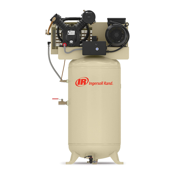
APPLICATION
IngersolI-Rand's
standard
two-stage lubricated
air compressors
are
single-acting,
air-cooled
machines.
Typical compressors
are
furnished
as compact,
self-contained,
air receiver tank mounted
units that are automatically
regulated
and driven by an electric
motor or gasoline
engine.
An air-cooled
aftercooler,
low oil level
shutdown
switch and automatic
drain valve are among the optional
accessories
that can be furnished.
Bare compressor
pumps and
baseplate-mounted
units are also available.
These compressors
may be used for a variety
of compressed
air
application
up to 250 PSIG (17.5 kg/cm2). Application
of these
compressors
as either a primary or supplementary
source of air is
virtually
unlimited
in industrial
plants, service
stations and auto
repair shops.
Supplementary
service
includes such uses as
furnishing
air at pressure
not carried
in regular shop lines, air at
isolated
locations,
and standby
service
for air when larger
compressors
are shut down.
TWO-STAGE
OPERATION
Two-stage
compressors
consist of one or two first-stage
cylinders
with the same bore size and one second-stage
cylinder with a
smaller
bore size.
Typical Two-Stage,
Two
Cylinder Unit
Typical Two-Stage,
Three
Cylinder Unit
The basic principle
of operation
is as follows:
On the suction
stroke
of the first-stage
piston(s),
air at atmospheric
pressure
enters the
cylinders
through the inlet filter(s)
and then the inlet valves located
in the head. On the compression
stroke of the first-stage
piston(s),
the air is compressed
to an intermediate
pressure
and discharged
through the discharge
valves(s)
into common
manifold(s).
From the
manifold(s)
the air passes through the intercooler
tubes, where the
heat of first-stage
compression
is removed.
On the suction stroke of
the second-stage
piston this cooled air enters the second-stage
cylinder
through the inlet valve. The compression
stroke of the
second-stage
piston compresses
the air to the final discharge
pressure
and forces it out through the discharge
valve into the
receiver
tank or system.
If cooling of the discharge
air is required,
© Ingersoll-Rand
Company
Printed
in U.S.A.
Form SCD-838A
August 2001
Advertisement
Table of Contents

Related Manuals for Ingersoll-Rand 2475N7.5-P


Summary of Contents for Ingersoll-Rand 2475N7.5-P
- Page 1 Ingersoll-Rand receiver tank or system. If cooling of the discharge air is required, compressor. Carefully read this manual before attempting operate or perform any maintenance.
-
Page 2: Installation
anair-cooled aftercooler should b einstalled between the compressor discharge and thereceiver tank orsystem. Formaintaining thereceiver tank orsystem a irpressure within SELECTING A LOCATION predetermined limits, the compressor may be operated with ELECTRIC MOTOR UNITS. For most electric motor units, select a automatic start &... - Page 3 Refer to the following material compatibility list. If there are incompatible materials present in your system, or if 11\ \ there are materials not included in the list, contact Ingersoll-Rand for recommendations. Shim beneath Floor line SYNTHETIC COMPRESSOR LUBRICANT isolator washer, if...
-
Page 4: Lubrication
24 Ah should be sufficient for cranking most electric start engines. /k CAUTION Do not operate without lubricant or with inadequate lubricant. Ingersoll-Rand is not responsible BATTERY CABLES. Refer to the following table for size and length compressor failure caused by inadequate recommendations. -
Page 5: Operation
80-125" 26.7-51.0" A = FULL level at bottom thread of oil fill opening on units without sight glass or dipstick. * = For Models 2000 and 2000P, use Ingersoll-Rand XL-740HT Compressor Oil in temperatures above 100°F B = ADD level below bottom thread of oil fill opening on units (37.7°0). - Page 6 COMPRESSOR CONTROLS Release any remaining tank pressure by slowly opening the manual drain valve. AUTOMATIC START & STOP CONTROL. This type of control Close the manual drain valve and apply power to the compressor. applies to electric motor driven models under 10 horsepower.
- Page 7 adjustment control, the span between cut-in and cut-out pressure The oil pump is equipped with an adjustable pressure regulator levels s witches isfactory setfor40_+ 4 PSIG and cannot be which may be reset if conditions warrant. Refer to the following adjusted.
- Page 8 Position of weight and thrust pin when unit is operating. TUBE CONNECTION ATMOSPHERE A = Oil Pump B = Oil Filter C = Oil Pressure Gauge Position of weight and thrust pin when unit is stopped. D = Oil Pressure Switch TUBE CONNECTION ATMOSPHERE...
- Page 9 OILCONSUMPTION CHECK MAINTENANCE SCHEDULE A rule of thumb in determining a "passing grade" for oil consumption • Check for oil leaks. is to consider consumption at or above 50 horsepower-hours • Check lubricant level. Fill as needed. Daily or Before ounce to be acceptable.
- Page 10 I)EFLECTIO!I .._/__" environments, and the level of maintenance. The exact effect of these factors on tank life is difficult to predict; therefore, Ingersoll-Rand recommends that you schedule a certified tank inspection within the first five years of compressor service. To...
- Page 11 _o_] _[oIo_€_ PROBLEM CHECK POINT 4, 8, 9, 19, 28, 35 Abnormal piston, ring or cylinder wear Air delivery drops off 1,6, 15, 16, 18, 19, 29 Automatic drain valve leaks or does not drain automatically 23, 24 Auxiliary valve chatters or leaks around stem Broken intercooler...
- Page 12 CHECK POSSIBLE CAUSE POSSIBLE SOLUTION POINT Clogged or dirty inlet and/or discharge line filter. Clean or replace. Loose beltwheel or motor pulley, excessive end play in motor Check beltwheel, motor pulley, crankshaft, drive belt tension shaft or loose drive belts. alignment.
- Page 13 FASTENER TORQUE TABLE 2340 2475 2545 7100 2000 & 2000P High Pressure Head Bolts Low Pressure Head Bolts Cylinder Flange Bolts Frame Cover Bolts Shaft Cover Bolts 12-15 Crankpin Cap Screws Unloader Cover Screws 11-15 LB-IN 11-15 LB-IN 11-15 LB-IN 36 LB-IN High Pressure Inlet Valve Screws...
-
Page 14: Wiring Diagrams
ELECTRICAL WIRING DIAGRAMS Single Phase Wiring To supply Wiring for optional electric drain valve Electric drain valve Supply Line Terminal SUPPI Load Terminal L2" Control Circuit Fuse HATS High Air Temperature Switch I F------_YZ_/ *MOTOR LOLS Low Oil Level Switch Motor Starter Coil Motor Starter Overload E>_I,... - Page 15 Typical Baseplate Unit INTERCOOLER -AIR INLET FILTER SAFETY/RELIEF OUTLET VALVE_ ENCLOSED BELTGUARD (OUTDOOR OPTION) INLET FILTER FLOW LEVEL AIR COOLED AFTERCOOLER COOLED SWITCH DRAIN AFTERCOOLER (OPTIONAL) (OPTIONAL) CONNECTION MOUNTING HOLE. < Typical Horizontal Simplex Unit AIRCOOLED AFTERCOOLER (OPTIONAL) INLET FILTERS CONSTANT SPEED SAFETY/RELIEF...
- Page 16 Typical Vertical Simplex Unit I ii Z'qEZEIIFE :Z I _,1_ : F T TI,,I --IR FFE,Z RE :3 kts_ _LI=4 [_:F(Fl .Fr: _RIII Typical Gasoline Engine Unit PRESSURE GAUGE, DISCHARGE & RECEIVER SAFETY/RELIEF VALVE, GASOLINE ENGINE DISCHARGE UNLOADER ENCLOSED ENGINE CLEANER INTERSTAOE SAFETY/RELIEF...
- Page 17 Company, but manufactured by others, shall carry whatever warranty the manufacturer conveyed to Ingersoll-Rand Company and which can be passed on to the Purchaser. The Company shall not be liable for any repairs, replacements, or adjustments the Equipment...
- Page 18 A PRECAUCl0N CAUSARA O PUEDE CAUSAR LESIONES MENORES manual, comuniquese con Ingersoll-Rand. Le recomendamos o dahos a la propiedad. guarde este manual y todas las publicaciones que vienen con su compresor...
-
Page 19: Instalacion
vMvulas de descarga hacia el o los mt31tiples comunes. Desde el o los Lea la placa de identificaci6n del compresor para verificar mt_ltiples, el aire pasa a trav6s de los tubos del interenfriador, donde corresponde al modelo solicitado y lea la placa del motor para verificar elimina... - Page 20 Ingersoll-Rand para obtener recomendaciones.. sobre el tanque receptor. Recomendamos instalar un juego aislador vibraciones en los modelos de motor a gasolina.
- Page 21 115V 230V 2O0V 230V 460V 575V Kohler Honda Kawasaki Ingersoll-Rand ARRANCADOR MAGN#TICO. Si el motor instalado en su unidad tiene un boton de reposicion del motor, este no requiere un arrancador magnetico.
-
Page 22: Operacion
Consulte a Ingersoll-Rand para obtener recomendaciones apagando la unidad hasta que se haya restaurado el nivel apropiado sobre sus condiciones de operaci6n especificas. - Page 23 "carga" (B) en los con palanca de encendido y apagado no tienen un modelos con motores Kawasaki y Honda y Ingersoll-Rand. control de ajuste diferencial. Tipico descargador (A = descarga, B = carga) PROCEDIMIENTOS DE AJUSTE (DISYUNTORES...
- Page 24 4. Fijese enlalectura del man6metro alaque s e desconecta elcompresor. SISTEMA DE DESCARGA EN EL ARRANQUE 5. Si e s necesario, repita el p rocedimiento de ajuste. En determinados modelos existe la funci6n de descarga en el arranque. Ajuste del range del disyuntor neum_tico.
- Page 25 Cuando sepierde lapresi6n del a ceite, ya sea debido alapagado proporcionando un conducto para que escape el aire a trav_s cornpresor oaunproblema delubricacion durante laoperacion descargador de admisi6n (si est& abierto) o (si est& cerrado) a trav_s cornpresor, eldescargador hidraulico se abre, accionando la valvula de retenci6n,...
- Page 26 CALENDARIO DE MANTENIMIENTO • Verifique que hay escapes de aceite. Diariamente • Revise el nivel del lubricante. Rellene seg6n antes de cada necesario. operaci6n • Vacie el condensado del tanque receptor (si no hay un dispositivo de drenaje automatico). Abra la valvula de drenaje manual,...
- Page 27 (en libras) multiplicando la Iongitud del tramo vida 6til del tanque es dificil de predecir; por Io tanto, Ingersoll-Rand (t) por 1/64. Por ejemplo, una Iongitud de tramo de 32" multiplicada recomienda programar una inspecci6n certificada del tanque...
- Page 28 PROBLEMA PUNTO DE COMPROBACION 4, 8, 9, 19, 28, 35 Desgaste anormal del cilindro, anillo o piston 1,6, 15, 16, 18, 19, 29 La entrega de aire disminuye La vMvula de drenaje autom&tica presenta filtraciones o no drena autom&ticamente La vMvula auxiliar tintinea o tiene filtraciones alrededor...
- Page 29 PUNTO POSIBLE CAUSA POSIBLE SOLUCION COMP. Entrada y/o filtro del tubo de descarga sucios o atascados. Limpie o reemplace. Rueda de banda o polea del motor sueltas, juego excesivo en el eje del motor o Revise la tensi6n y alineaci6n de la rueda de banda, polea del motor, cigL]effal...
- Page 30 TABLA DE TORSIONES DE LOS FIJADORES 2340 2475 2545 7100 2000 Y 2000P Pernos prisioneros de alta presi6n Pernos prisioneros de baja presi6n Pernos de reberde del cilindre Pernos de cubierta de la armaz6n Pernos de cubierta del eje 12-15 Tornilles de cabeza del pasador...
- Page 31 DIAGRAMAS DE CABLEADO ELECTRICO Cableado monofasico AI suministro Cableado para la v&lvula de drenaje el6ctrico opcional Valvula de drenaje electrico Terminal de linea de suministro Terminal de carga Fusible del circuito de control I F----_YL,_/ *MOTOR HATS Interruptor de alta temperatura del aire (#) LOLS Interruptor...
- Page 32 Tipica unidad de placa base INTERCOOLER -AIR INLET FILTER SAFETY/RELIEF OUTLET VALVE_ ENCLOSED BELTGUARD (OUTDOOR OPTION) INLET FILTER FLOW LEVEL AIR COOLED AFTERCOOLER COOLED SWITCH DRAIN AFTERCOOLER (OPTIONAL) (OPTIONAL) CONNECTION MOUNTING HOLE. < Tipica unidad simplex horizontal AIRCOOLED AFTERCOOLER (OPTIONAL) INLET FILTERS CONSTANT...
- Page 33 Tipica unidad simplex vertical I ii Z'qEZEIIFE :Z I _,1_ : F T TI,,I --IR FFE,Z RE :3 kts_ _LI=4 [_:F(Fl .Fr: _RIII Tipica unidad con motor a gasolina PRESSURE GAUGE, DISCHARGE & RECEIVER SAFETY/RELIEF VALVE, GASOLINE ENGINE DISCHARGE UNLOADER ENCLOSED ENGINE CLEANER...
- Page 34 Compar_ia. Los accesorios o equipos provistos por la Compafiia pero fabricados por otros mantendr_n todas las garantia traspasadas a Ingersoll-Rand Company por su fabricante y que puedan ser transferidas al Comprador. La Compafiia no se har& responsable de reparaciones,...
Need help?
Do you have a question about the 2475N7.5-P and is the answer not in the manual?
Questions and answers