Advertisement
Ensure that the operator reads and understands the
decals and consults the manuals before maintenance or
operation.
Ensure that the Operation and Maintenance manual is
not removed permanently from the machine.
Ensure that maintenance personnel are adequately
trained, competent and have read the Maintenance
Manuals.
IRN 7.5 − 15 HP (5.5 − 11 kW)
OPERATION AND MAINTENANCE MANUAL
C.C.N. : 80442981
REV.
DATE
PRINT LANGUAGE
ENGLISH
FRENCH
PORTUGUESE
SPANISH
: A
: JANUARY 2007
Advertisement
Table of Contents

Related Manuals for Ingersoll-Rand IRN 7.5/5.5 kW


Summary of Contents for Ingersoll-Rand IRN 7.5/5.5 kW
- Page 1 IRN 7.5 − 15 HP (5.5 − 11 kW) OPERATION AND MAINTENANCE MANUAL PRINT LANGUAGE ENGLISH FRENCH PORTUGUESE SPANISH Ensure that the operator reads and understands the decals and consults the manuals before maintenance or operation. Ensure that the Operation and Maintenance manual is not removed permanently from the machine.
- Page 2 Register on−line at air.irco.com/registration.htm Ingersoll−Rand Industrial Air Solutions Swan Lane Hindley Green Wigan WN2 4EZ Ingersoll Rand Asia Pacific C/O Ingersoll−Rand South East Asia (Pte) Ltd. 42 Benoi Road Singapore 629903 Ingersoll−Rand Industrial Air Solutions P.O. Box 1840 800−D Beaty Street...
-
Page 3: Table Of Contents
CONTENTS & ABBREVIATIONS CONTENTS ABBREVIATIONS & SYMBOLS CONTENTS #### Contact Ingersoll Rand for serial number −>#### Up to Serial No. FOREWORD ####−> From Serial No. Not illustrated Option DECALS Not required As required SAFETY Sitemaster/Sitepack High ambient machine Watercooled machine... -
Page 4: Foreword
The contents of this manual are considered to be proprietary and The intended uses of this machine are outlined below and examples confidential to Ingersoll Rand and should not be reproduced without the of unapproved usage are also given, however Ingersoll Rand cannot prior written permission of Ingersoll Rand. -
Page 5: Decals
DECALS ISO SYMBOLS GRAPHIC FORM AND MEANING OF ISO SYMBOLS Prohibition / Mandatory Information / Instructions Warning WARNING: Electrical shock risk. WARNING − Pressurised vessel. WARNING − Hot surface. WARNING − Pressurised component or WARNING − Air/gas flow or Air discharge. Do not breathe the compressed air from this system. - Page 6 DECALS AUTOMATIC RESTART MAINTENANCE MAINTENANCE PROHIBITED COOLANT DRAIN CONDENSATE DRAIN FILTER FRAGILE KEEP DRY THIS WAY UP USE NO HOOKS NO SIDE CLAMPS HOURS Use ULTRA−Plus Coolant only POWER INSPECT Failure to use the specified coolant may result in damage to the machine Every X months, if sooner than required by CHANGE / REPLACE CLEAN...
- Page 7 GRAPHIC FORM AND MEANING OF ANSI SYMBOLS DANGER INTAKE AIR. Can contain carbon monoxide or other contaminants. Will cause serious injury or death. Ingersoll Rand air compressors are not designed, intended or approved for breathing air. Compressed air should not be used for breathing air applications unless treated in accordance with all applicable codes and regulations.
- Page 8 32343527 Decal, warning high pressure 22539431 Decal, control panel (Non − Dryer) 32343550 Decal, warning exposed fan 16543464 Decal, Ingersoll Rand logo 32343568 Decal, warning hazardous voltage 22369714 Decal, Intellidrive http://air.irco.com IRN 7.5 − 15 HP (5.5 − 11 kW)
- Page 9 DECALS (A.N.S.I.) Item Qty. Description Item Qty. Description 32343899 Decal, warning flying debris 22394381 Decal, power inlet 22369706 Decal, warning two minutes before 92867530 Decal, coolant drain on base. service 32343543 Decal, air discharge (Base mount only) 22533772 Decal, Dryer bypass instruction 32343519 Decal, contaminated air (Base mount (Dryer models only)
- Page 10 22382238 Spec., compressor package data plate 22539431 Decal, control panel Non−dryer packages 22533772 Decal, dryer bypass instruction. (Dryer models only) 16543464 Decal, Ingersoll Rand logo 92930668 Decal, no maintenance before 22369714 Decal, Intellidrive referring manual 92867498 Decal, air discharge −...
-
Page 11: Safety
Ingersoll Rand recommends that only filters with metal bowls should be used on a pressurised system. Lifting equipment must be properly rated for the weight of the compressor. - Page 12 As waste water regulations vary by country and region it is the responsibility of the user to establish the limitations and regulations in their particular area. Ingersoll Rand and its associated distributors are happy to advise and assist in these matters.
-
Page 13: General Information
RECOMMENDED IN THIS SECTION. Dryer motor Fan motor 3 SIZING OF ELECTRICAL COMPONENTS NOT SUPPLIED BY INGERSOLL RAND IS THE RESPONSIBILITY OF THE CUSTOMER Power on AND SHOULD BE DONE IN ACCORDANCE WITH THE INFORMATION ON THE COMPRESSOR DATA PLATE, N.E.C., AND Pressure set potentiometer LOCAL ELECTRICAL CODES. - Page 14 GENERAL INFORMATION PIPING AND INSTRUMENTATION AR Air receiver (option) 22.Valve, check Integral dryer (option) 23.Recuperator 1. Filter, air 24.Valve, isolation 2. Valve, inlet 25.Moisture separator 3. Airend assembly 26.Valve, check 4. Motor 27.Evaporator 5. Controller, drive 28.Indicator, dew point 6. Tank, separator − coarse 29.Valve, condensate 7.
-
Page 15: Installation / Handling
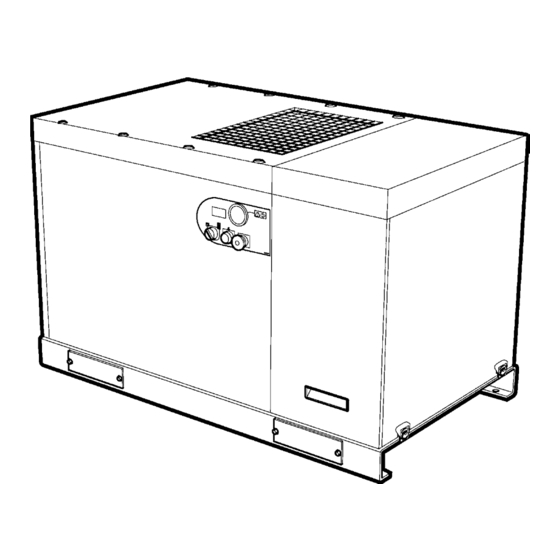
INSTALLATION / HANDLING 7.5−15HP 80 GALLON A Air inlet R Coolant fill B 1/4” (6mm) electric drain valve Coolant level sight glass C Green power on light Coolant drain D On/off selector switch U Dewpoint indicator E Air exhaust Airend relief valve F Pressure / maintenance indicator W Package lifting points G Emergency stop button... - Page 16 INSTALLATION / HANDLING 7.5−15HP BASEPLATE Air inlet Q Variable / fixed speed toggle switch R Coolant fill Valve, electric drain 1/4” (6mm) Coolant level sight glass C Green power on light Coolant drain D On/off selector switch U Dewpoint indicator Air exhaust Airend relief valve Pressure / maintenance indicator...
- Page 17 INSTALLATION / HANDLING 5−11kW BASEPLATE Air inlet Q Variable / fixed speed toggle switch R Coolant fill Valve, electric drain 1/4” (6mm) Coolant level sight glass C Green power on light Coolant drain D On/off selector switch U Dewpoint indicator Air exhaust Airend relief valve Pressure / maintenance indicator...
- Page 18 INSTALLATION / HANDLING 7.5−15HP 120 GALLON Air inlet Q Variable / fixed speed toggle switch R Coolant fill Valve, electric drain 1/4” (6mm) Coolant level sight glass C Green power on light Coolant drain D On/off selector switch U Dewpoint indicator Air exhaust Airend relief valve Pressure / maintenance indicator...
- Page 19 INSTALLATION / HANDLING 5−11kW 272 LITRE Air inlet Q Variable / fixed speed toggle switch R Coolant fill Valve, electric drain 1/4” (6mm) Coolant level sight glass C Green power on light Coolant drain D On/off selector switch U Dewpoint indicator Air exhaust Airend relief valve Pressure / maintenance indicator...
- Page 20 INSTALLATION / HANDLING 5−11kW 500 LITRE Air inlet Q Variable / fixed speed toggle switch R Coolant fill Valve, electric drain 1/4” (6mm) Coolant level sight glass C Green power on light Coolant drain D On/off selector switch U Dewpoint indicator Air exhaust Airend relief valve Pressure / maintenance indicator...
- Page 21 Ensure that the correct fork lift truck slots or marked lifting points are in marine environments. For further advice or assistance consult your used whenever the machine is lifted or transported. local Ingersoll Rand representative. UNPACKING ELECTRICAL CONNECTION The compressor will normally be delivered with a polythene cover.
- Page 22 Their safety can be affected by either synthetic coolants or the additives used in mineral oils. 2. Air Receiver Ingersoll Rand recommends that only filters with metal bowls 3. Air Dryer should be used on any pressurised system.
- Page 23 INSTALLATION / HANDLING 60/50Hz IRN 7.5 / 5.5 kW IRN 10 / 7.5 kW IRN 15 / 11 kW COMPRESSOR Nominal pressure PSIG (bar) (7.93) (10.34) (13.79) (7.93) (10.34) (13.79) (7.93) (10.34) (13.79) Maximum operating pressure PSIG(bar) (8.62) (11.03) (14.48) (8.62) (11.03) (14.48)
- Page 24 INSTALLATION / HANDLING ELECTRICAL DATA − ALL UNITS IRN 7.5HP / 5.5kW Standard voltage Low Voltage High Voltage 200V 230V 380V 400V 460V Drive motor Motor enclosure IP65 Power 7.5HP / 5.5kW Full load current (maximum) 27.0 23.5 15.0 14.3 12.4 Starts per hour (maximum) ELECTRICAL DATA...
- Page 25 INSTALLATION / HANDLING ELECTRICAL DATA − ALL UNITS IRN 15HP / 11kW Standard voltage Low Voltage High Voltage 200V 230V 380V 400V 460V Drive motor Motor enclosure IP65 Power 15HP / 11kW Full load current (maximum) 46.0A 40.0A 23.4A 22.2A 19.3A Starts per hour (maximum) ELECTRICAL DATA...
- Page 26 OPERATING INSTRUCTIONS GENERAL OPERATION The power transmission from the drive motor to the airend male rotor is by direct drive. The compressor is an electric motor driven, single stage screw compressor, complete with accessories piped, wired and baseplate mounted. It is a totally self contained air compressor package. By cooling the discharge air, much of the water vapour naturally contained in the air is condensed and may be drained from the downstream piping and equipment.
-
Page 27: Operating Instructions
OPERATING INSTRUCTIONS 1. PRESSURE INDICATOR / MAINTENANCE INDICATOR / 5. DEWPOINT INDICATOR (DRYER ONLY) HOURMETER Green indicates an acceptable dewpoint, red indicates a dewpoint Indicates the system pressure, time to maintenance, real time, run above 50_F(10_C), and blue indicates a freezing risk. hours and fault indication. - Page 28 OPERATING INSTRUCTIONS WARNING (2) Maintenance Indicator Make sure that all protective covers are in place. (3)Package Discharge Pressure Indicator Cooling air flow exhaust may contain flying debris. Safety (4) Real Time Clock − 24 hour time format WITHOUT AM OR Protection should be worn at all times to avoid injury.
- Page 29 OPERATING INSTRUCTIONS Right Button The default Pressure indication will be in Bar. The default indication can be changed to Pressure in PSI or kPa by navigating to the desired Increment a value when entering password (if applicable). pressure display and waiting 15 seconds for the display to time out. When the 15 second display timer times out, the selected pressure Setting maintenance interval.
- Page 30 In normal conditions it should be operating in the green region. If the unit continues to operate in the red region, contact your local Ingersoll Rand representative. In order to bypass the dryer, stop the IRN compressor and lock and tag it out.
-
Page 31: Maintenance Schedule
Check the operation of the high operation necessary. 3000 hours temperature protection switch (109_C). Visual check of Report immediately, contact Ingersoll Rand Change the coolant filter. machine for any authorized distributor for assistance if in Check scavenge screen for blockage, leaks, dust build up doubt clean if required. - Page 32 MAINTENANCE ROUTINE MAINTENANCE all hazards present are known (e.g. pressurised components, electrically live components, removed panels, covers and guards, This section refers to the various components which require extreme temperatures, inflow and outflow of air, intermittently moving periodic maintenance and replacement. parts, safety valve discharge etc.).
-
Page 33: Maintenance
MAINTENANCE 10.Replace and tighten oil fill cap. 5. Remove the new Ingersoll Rand replacement cartridge from its protective package. 11.Dispose of waste properly. 6. Apply a small amount of lubricant to the cartridge seal. 7. Screw the new cartridge down until the seal makes contact with the COOLANT FILTER CHANGE PROCEDURE housing, then hand tighten a further half turn. - Page 34 (Used filter elements must be disposed of in accordance with local regulations.) • Adjustable time off (0.5 − 45 minutes) Use only genuine Ingersoll Rand replacement elements. • Stainless steel operator • LED to indicate electrical power is on •...
- Page 35 MAINTENANCE 1. Stop compressor, lock and tag out machine. REFRIGERANT LEAKS IN THE REFRIGERATION CIRCUIT The unit is despatched in perfect working order, already charged. Refrigerant leaks may be identified by tripping of the refrigeration overload protector . IF A LEAK IS DETECTED IN THE REFRIGERANT CIRCUIT, SEEK TECHNICAL ASSISTANCE.
-
Page 36: Trouble Shooting
Check hot gas valve setting. NOTES: § Must be carried out by a competent electrician. † This work is recommended to be carried out only by an Ingersoll Rand authorized service technician. http://air.irco.com IRN 7.5 − 15 HP (5.5 − 11 kW) - Page 37 Ensure ambient temperature is greater than 35_F (2_C). NOTES: § Must be carried out by a competent electrician. † This work is recommended to be carried out only by an Ingersoll Rand authorized service technician. http://air.irco.com IRN 7.5 − 15 HP (5.5 − 11 kW)
Need help?
Do you have a question about the IRN 7.5/5.5 kW and is the answer not in the manual?
Questions and answers