
Related Manuals for Ingersoll-Rand INTELLISYS SSR Series


Summary of Contents for Ingersoll-Rand INTELLISYS SSR Series
- Page 1 SSR INTELLISYS ROTARY TROUBLESHOOTING GUIDE • Original Intellisys • SE & SG • Problems • Procedures • Warranty Information APDD 749 September 1999...
- Page 2 SSR INTELLISYS ROTARY TROUBLESHOOTING GUIDE The following is a guide to be used when identifying the root cause of a compressor problem. Forms have also been developed for the SE and SG controller and must be filled in if the controller is to be returned to the factory under warranty. Any controller returned to the factory must have all shaded areas of the form filled in completely and a copy of the form sent with the controller.
- Page 3 TABLE OF CONTENTS INTRODUCTION............................1 TABLE OF CONTENTS..........................2 HOW TO USE ...............................4 SE INTELLISYS CONTROLLER WARRANTY INFORMATION SHEET ........5 SG INTELLISYS CONTROLLER WARRANTY INFORMATION SHEET........6 PROBLEMS SE C ...........7 ONTROLLER HUTS DOWN WITH READY TO START IN THE DISPLAY SG C ...........8 ONTROLLER HUTS DOWN WITH READY TO START IN THE DISPLAY...
-
Page 4: Table Of Contents
1.7 TEMPERATURE Background..............................31 Procedure ..............................32 1.8 VIBRATION Background..............................32 Procedure ..............................32 OTHER 1.9 REMOTE ALARM APPLICATION Background..............................32 Procedure ..............................32 2.1 STEPPER MOTOR TEST Background..............................34 Procedure ..............................34 2.2 DRIVER CHIP TEST Background..............................34 Procedure ..............................35 2.3 LIMIT BOARD TEST Background..............................36 Procedure ..............................36 2.4 PRESSURE SENSOR CHECK OUT Background..............................37 Procedure ..............................38 2.5 TRIAC OUTPUTS... - Page 5 USER INSTRUCTIONS Identify the problem that is being experienced with the controller or compressor. Locate the problem in the table of contents under the PROBLEMS section. Turn to that page and follow the flow chart through the diagnostics. If the flow chart refers to another paragraph, find the paragraph number in the table of contents and turn to that page.
- Page 6 SE INTELLISYS CONTROLLER GENERAL INFORMATION Date: Customer: Distributor: Technician: Machine S/N: Model Number Total Hours: Loaded Hours: NEMA Rating: Starter Type: Ambient Temp: Start-up Date: Problem Description (What, How, When): INTELLISYS SE INFORMATION Intellisys S/N EPROM Version: Offline Pressure: Online Pressure: Mode of Operation: Options: Comm.
- Page 7 SG INTELLISYS CONTROLLER GENERAL INFORMATION Date: Customer: Distributor: Technician: Machine S/N: Model Number Total Hours: Loaded Hours: NEMA Rating: Starter Type: Ambient Temp: Start-up Date: Problem Description (What, How, When): INTELLISYS SG INFORMATION Intellisys S/N EPROM Version: Offline Pressure: Online Pressure: Mode of Operation: Options: Comm.
- Page 8 SE CONTROLLER: SHUT DOWN “READY TO START” = MACHINE WAS OPERATIONAL AND IN THE RUNNING MODE. MACHINE STOPS AND DISPLAYS “READY TO START” OR SHUTS DOWN WITH BLANK DISPLAY INCOMING VOLTAGE DIPS BELOW 30% SERVICE APPLICATION, CHECK PHASE UNBALANCE, and SERVICE WIRE AMPACITY.
- Page 9 SG CONTROLLER: SHUTDOWN “READY TO START” = MACHINE WAS OPERATIONAL AND IN THE RUNNING MODE. MACHINE STOPS AND DISPLAYS “READY TO START” OR SHUTS DOWN WITH BLANK DISPLAY INCOMING VOLTAGE DIPS BELOW 30% SERVICE APPLICATION, CHECK PHASE UNBALANCE, and SERVICE WIRE AMPACITY.
-
Page 10: Ontroller Locks - Up
= UNIT RUNNING. PUSHING THE STOP BUTTON DOES NOT CAUSE ANYTHING TO ORIG,SE,SG: HAPPEN AND NO ALARMS ARE INDICATED, OR READY TO START IN THE DISPLAY CONTROLLER LOCK-UP. UNIT WILL NOT STOP AND PRESSING THE START BUTTON DOES NOT CAUSE START OR ALARM. CYCLING OR READY TO START WILL NOT START POWER WILL RESET BUT PROBLEM OCCURS AGAIN. - Page 11 ORIG,SE,SG: TRIAC IS ON AND SHOULD BE OFF OR TRIAC IS OFF AND SHOULD BE ON ORIGINAL INTELLISYS SE CONTROLLER SG CONTROLLER SEE PARAGRAPH 2.5 SEE BLUE FSM SECTION B, SHEET 28 USE SE I/O TEST KIT...
- Page 12 = VALVE COMMANDED TO MOVE TO OPEN OR CLOSED LIMIT SWITCH AND CONTROLLER NEVER ORIG, SG: CHECK INLET CONTROL RECEIVES SIGNAL FROM LIMIT SWITCH CONFIRMING THE VALVE MADE IT THERE. YES SUSPECT BAD OPEN LIMIT SWITCH CONFIRM 24 VAC TO BOARD SEE PROCEDURE 2.3 DID VALVE MOVE PAST YES.
- Page 13 ORIG, SG: CHECK INLET CONTROL = UNIT UNLOADED AND INLET VACUUM LESS THAN THREE PSI. YES. SUSPECT 1AVPT TRANSDUCER PROBLEM, OR LEAK IN SENSING LINE YES. IS THE AIREND TURNING? SUSPECT SLIPPING GEAR UNLOADED IS THE INLET VALVE CLOSED? NO. ORIGINAL CONTROLLER - CHECK FOR SLIPPING COUPLING SG CONTROLLER - CHECK POSITION OF CLOSED LIMIT SWITCH...
- Page 14 ORIG, SE, SG: LOW UNLOADED SUMP = UNIT UNLOADED AND SUMP PRESSURE IS LESS THAN 15 PSI FOR 10 SECONDS SUSPECT SLIPPING COUPLING BAD STEPPER MOTOR. SEE PROCEDURE 2.1 BAD DRIVER CHIP. SEE PROCEDURE 2.2 MPCV STUCK OPEN IF PUMPING INTO AN OPEN SYSTEM IF NONE OF THE ABOVE THEN PROBABLY A BINDING INLET VALVE.
- Page 15 = SUMP PRESSURE IS GREATER THAN 15 PSIG ABOVE THE RATED PRESSURE OF THE UNIT. ORIG, SG, SE: HIGH SUMP PRESSURE BAD COOLANT BYPASS OR BAD AIR FILTER. WATER IN THE SYSTEM CLOGGED SEPARATOR ELEMENT WATER IN THE SYSTEM CAUSING CORROSION IN THE VALVE.
- Page 16 ORIG, SG, SE: HIGH AIREND TEMPERATURE = AIREND DISCHARGE TEMPERATURE EQUAL TO OR GREATER THAN 228°F. NO. CORRECT COOLANT AND TRY AGAIN. YES. IS COOLANT LEVEL CORRECT? YES. SUSPECT PROBLEM WITH COOLANT STOP VALVE. DOES UNIT SHUT DOWN IN LESS THAN 10 SECONDS AFTER START-UP? CHECK WIRING AND VALVE OPERATION (SEE PROCEDURE 2.5) AIR-COOLED = BAD ENVIRONMENT WATER-COOLED = BAD WATER...
- Page 17 ORIG, SG, SE: MAIN OR FAN MOTOR OVERLOAD = OVERLOAD CONTACT OPEN FOR MORE THAN ONE SECOND. PLACE OVERLOAD RELAY IN MANUAL CORRECT HEATER SELECTION OR OVERLOAD SETTING. RESET MODE NO. POTENTIAL PROBLEM WITH WIRING FROM OVERLOAD TO CONTROLLER OR CONTROLLER. ORIGINAL &...
- Page 18 ORIG, SG, SE: YES. DOES UNIT SHUT DOWN IN LESS STARTER FAULT THAN 12 SECONDS AFTER START-UP? YES. IS AIREND DISCHARGE TEMPERATURE GREATER THAN 210°F AT TIME OF SHUTDOWN? IS THIS THE ORIGINAL INTELLISYS CONTROLLER? CORRECT COOLANT AND TRY AGAIN YES.
- Page 19 FROM STARTER FAULT CHART ORIGINAL INTELLISYS CONTROLLER MEASURE VOLTAGE AC TERMINAL BTS1-33 AND BTS1-3 IS THE VOLTAGE GREATER THAN 110 VAC? NO. BAD CONTACT ON E-STOP YES. MEASURE VOLTAGE AC TERMINAL BTS1-31 AND BTS1-3 IS THE VOLTAGE GREATER THAN 110 VAC? NO.
- Page 20 = 115 VOLTS AC IS NOT APPLIED TO THE CONTROLLER BUT CONTROLLER IS POWERED-UP. SG, SE: NO CONTROL POWER SG CONTROLLER: MEASURE VOLTAGE AC SE CONTROLLER: P1 10 AND TERMINAL 1TB-1 MEASURE VOLTAGE AC TERMINAL BTS1-6 AND J4-29 IS THE VOLTAGE GREATER THAN 110 VAC? IS THE VOLTAGE GREATER THAN 110 VAC?
- Page 21 = NO INLET VACUUM SENSED 2 SECONDS AFTER STARTING. ORIG, SG, SE: CHECK MOTOR ROTATION SE CONTROLLER: NO SUMP PRESSURE SENSED 2 SECONDS AFTER STARTING. IS THE ROTATION CORRECT? DISCONNECT, LOCK AND TAG POWER IN OFF POSITION. INTERCHANGE TWO LEADS AND TRY AGAIN.
- Page 22 = BOTH LIMIT SWITCHES ARE ENGAGED AT THE SAME TIME. ORIG, SG: STEPPER LIMIT SWITCH MEASURE THE VOLTAGE ON THE RED AND BLACK WIRE OF THE LIMIT BOARD SG INTELLISYS CONTROLLER: ORIGINAL INTELLISYS CONTROLLER: IS THE VOLTAGE 2VDC? IS THE VOLTAGE 5VDC? POTENTIAL PROBLEM WITH NO.
- Page 23 = REMOTE START BUTTON IS PRESSED WHILE REMOTE STOP CONTACT IS STILL OPEN. ORIG, SG, SE: REMOTE STOP FAILURE SG INTELLISYS CONTROLLER ORIGINAL INTELLISYS CONTROLLER SE INTELLISYS CONTROLLER MEASURE VOLTAGE MEASURE VOLTAGE MEASURE VOLTAGE BETWEEN P3 TERMINAL 19 & 20 BETWEEN BTS2-6 AND BTS2-7 BETWEEN J1 TERMINAL 3 &...
- Page 24 = REMOTE START BUTTON IS PRESSED AND HELD CLOSED FOR MORE THAN 7 ORIG, SG, SE: REMOTE START FAILURE SECONDS AFTER A CONFIRMED START. ORIGINAL INTELLISYS CONTROLLER: SG INTELLISYS CONTROLLER: CONNECT DC VOLT METER TO BTS2-4 AND BTS2-5. CONNECT DC VOLT METER TO P3 TERMINAL 21 & 22 START UNIT USING LOCAL START BUTTON.
-
Page 25: Hort Separator Element Life
ORIG, SG, SE: SHORT SEPARATOR ELEMENT LIFE HIGH PRESSURE DIFFERENTIAL? BYPASSED INLET FILTER INADEQUATE INLET FILTER FOR ENVIRONMENT LOW DIFFERENTIAL OR COOLANT CARRY OVER BAD MPCV BAD OR OLD COOLANT HOLE IN THE ELEMENT UNIT QUICK CYCLING WATER IN THE COOLANT UNIT RUNNING TOO COLD CLOGGED SCAVENGE ORIFICE OR SCREEN... - Page 26 USE THIS PAGE FOR NOTES:...
-
Page 27: Procedure
Power Outage: Background Power outage may have occurred during operation. Any power outage in excess of 250 ms (.25 sec) will cause the control circuit to reset. This can occur in installations with automatic reset circuit breakers. Electrical disturbances can also occur from power company interruptions such as lightning storms. -
Page 28: Grounding Problems Background
Grounding Problems: Background A poor ground system can cause severe electrical problems. Electrical control systems can experience both over voltage and voltage sag conditions due to a poor ground. This can cause nuisance shutdowns, damage to power supply circuits, communications errors, and even be a safety hazard for fault conditions. Electrical fault conditions must have a low resistance path to earth ground. - Page 29 Disconnect power from machine. Set the meter for amps AC and connect the meter in series with the ground wire provided to the machine. If a recording meter is used (Fluke 87), set to 100 ms record mode. A recording meter is the preferred measurement for intermittent problems.
-
Page 30: Procedure
Set the meter for DC amps and record value in Amps DC. If measured value is greater than, or equal to, .25 Amps, a problem exists. Isolate electrical devices in compressor package and determine the source of ground current. Causes may include: faulty wiring, moisture contamination of electrical connections, motor overloads (current transformer type), control transformer, insulation breakdown of power leads, externally wired devices (remote start/stop, remote starter wiring, Sequencer, IRI, etc.) -
Page 31: Procedure
measurements return to normal, repeat procedure and use process of elimination to find cause. External 5 VDC Short Circuit: Background The Intellisys provides two 5 VDC signals for external use. The logic supply voltage is used by the Intellisys to supply power for internal circuitry such as the EPROM, RAM, Microprocessor, etc. -
Page 32: Moisture Background
This voltage measurement can be made with a Fluke 87 meter (or equivalent). A recording meter (Fluke 87) is preferred for intermittent problems. Set meter for Volts DC and connect and take measurements as noted: Connect from J3-25 to J3-24 Expected value = 5.0 VDC +/- .2 VDC Environmental Problems: Moisture:... -
Page 33: Procedure
temperature of 158° F. Although this is 43° F margin above ambient conditions, the rise above ambient must be accounted for. The typical rise above ambient inside the starter enclosure is 20° F. This is due to heat generated by the electrical equipment inside the enclosure, such as the control transformer, contactors,etc. - Page 34 lamp. If an inductive load is used, such as a relay coil, the rating should be reduced to maximum of 2.5 Amps, 250 VAC. The use of inductive loads can cause excessive arcing of these contacts. Excessive arcing can cause radiated interference (RFI) that can affect the Intellisys.
-
Page 35: Procedure
2.1 STEPPER MOTOR TEST PROCEDURE Background The stepper motor is a motor that can be moved in discrete increments of .9° for the Original Intellisys and .45° for the SG Intellisys. The motor is a constant torque device that is controlled by driver chips on the starter interface board or the power supply board. -
Page 36: Procedure
reverses polarity to cause the stepper motor to move in the proper direction. A shorted stepper motor will almost always damage the driver chips on the Original Intellisys but will simply illuminate an overload on the SG Intellisys. See FSM for more information on the SG. -
Page 37: Procedure
2.3 LIMIT BOARD TEST PROCEDURE Background The limit board contains two optical switches each of which emits an infrared light beam. When the light beam is interrupted, the voltage changes in a circuit that tells the controller the position of the valve. Procedure To perform this procedure, disconnect, lock and tag the incoming power. -
Page 38: Pressure Sensor Check Out Background
2.4 PRESSURE SENSOR CHECK OUT Background The pressure sensors used on the Intellisys controllers use a 5 VDC supply and turn it into a varying voltage signal to the controller. The SE and Original use a 0-50 mv signal and the SG uses a .5-4.5 VDC signal. Both supply and signal voltages can be measured. -
Page 39: Procedure
Procedure With a known good incandescent light connected to the output terminal, a digital voltmeter can easily read whether or not the triac is on or off. 115 VAC means on, a 0 VAC means off. This is the best way to monitor outputs on any Intellisys Controller. - Page 40 Connect voltmeter set to volts DC to terminals J1-10 & 9. You should read 5 VDC when 1M is de-energized and 0 VDC when 1M is energized. Star Delta Starting Only Contact 1Sa (mounted on the 1S starter contactor). Connect voltmeter set to volts DC to terminals J1-8 & 7. You should read 5 VDC when 1S is de-energized and 0 VDC when 1S is energized.
-
Page 41: Procedure
Power Outage: Background Power outage may have occurred during operation. Any power outage in excess of 250 ms (.25 sec) will cause the control circuit to reset. This can occur in installations with automatic reset circuit breakers. Electrical disturbances can also occur from power company interruptions such as lightning storms. -
Page 42: Procedure
the controller. To measure the 24 VAC, connect the meter to J1 terminal 1 and 2 on the power supply board. To measure the 12 VDC to the controller, connect the meter set in volts DC to J4 terminal 1 & 2 on the power supply board. Intellisys 24 VAC Supply: Background The Intellisys power supply is fed from the 24 VAC secondary of the control... -
Page 43: Procedure
made via connector P9. P9 is a 5-pin connector located on the left side of the controller (viewed from the front). The “Option Module” should always be installed or removed with power off. Note: the “Option Module” can be potentially damaged if installed with power on. -
Page 44: External Electrical Disturbances Background
4.0 External Electrical Disturbances: Background These are defined as sources of interference that can adversely affect signal integrity of control systems and wiring interfaces. These types of problems can be caused by Radio Frequency Interference (RFI), Electro-Magnetic Interference (EMI), Electro-Static Discharge (ESD), lightning disturbances, and power line transients and surges. - Page 45 equipment, or other equipment that exhibits excessive electrical arcing during operation (i.e. DC brush motors). The level of disturbance is generally known as field strength. The electric field strength is measured in volts per meter (V/m). A hand held 5 watt transmitter can generate 10 V/m electric field strength at a distance of approximately 1 foot.
- Page 46 Transients and surges can be caused by a variety of reasons. A few of these include: Poor or ungrounded equipment. Improperly sized power distribution systems that generate disturbances when switching large inductive or capacitive loads. Ground fault conditions. Equipment phase to ground or phase to phase conditions. Arc welding to compressor or surrounding equipment.
-
Page 47: Procedure
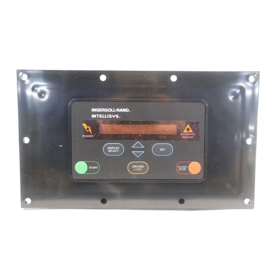
5.0 Membrane Switch Background The membrane switch is part of the user interface to the Intellisys control. It is a matrix of switches bonded to the Intellisys controller and electrically connected to the control circuit board. The internal membrane switch wiring to the physical switches is accomplished through conducted traces made of silver conductive ink. -
Page 48: Figure 2 - Sg Membrane Schematic
S1 1-2 S2 1-4 S3 5-4 S4 Start 3-2 S5 Unload 3-4 S6 Load 5-6 S7 Unloaded Stop 7-6 S8 Down Arrow 7-8 S9 Up Arrow 5-8 Figure 2. SG Membrane Schematic... - Page 49 Mod/ACS 1-8 Select Up Arrow 1-7 Setpoint Down Arrow 1-6 On/Offline 2-8 Select Down Arrow 2-7 Set 2-6 Unload 3-8 Reset 3-7 Setpoint Up Arrow 3-6 Start 4-8 Unloaded Stop 4-7 Test 4-6 Figure 3. SSR Original Intellisys Membrane Schematic...
- Page 50 ___________________________________________ ________________________________ Purchase Order No. Date ____________________________________________________________________________________ Name (Last) (First) (M. I.) ____________________________________________________________________________________ Company ____________________________________________________________________________________ Title ____________________________________________________________________________________ Address ____________________________________________________________________________________ City State _____________________________ ________________________________________________ Phone Price * Title Qty. Req'd $6.00 EACH Intellisys Rotary Troubleshooting Guide Form APDD 749 $1.00 PAD APDD 749 SUP 1 $1.00 PAD APDD 749 SUP 2...
Need help?
Do you have a question about the INTELLISYS SSR Series and is the answer not in the manual?
Questions and answers