Table of Contents
Advertisement
Quick Links
EUROCOM 8500 DeskNote
User's Manual
This manual covers EUROCOM 8500P, 8500P3 and 8500C DeskNote™
models.
All distinctions between models are covered throughout this
manual. Enjoy your EUROCOM 8500 DeskNote.
Notice
The company reserves the right to make any updates revisions or changes
to the information contained herein as and when deemed necessary. The
company is under no obligation to notify any purchaser or end-user of such
actions in advance or afterwards.
1999
Trademarks
DeskNote
is a registered trademark of Eurocom Corporation
IBM PC, OS/2, PS/2, EGA, and VGA are registered trademarks of
International Business Machines Corporation.
Intel, Pentium are registered trademarks of Intel Corporation.
MS-DOS, Microsoft Windows, Windows NT and Microsoft Mouse are
registered trademarks of Microsoft Corporation.
Sound Blaster Pro is a registered trademark of Creative Labs, Inc.
SystemSoft is a registered trademark of SystemSoft Corp.
Other brand and product names are registered trademarks of their
respective companies.
Advertisement
Table of Contents

Subscribe to Our Youtube Channel
Related Manuals for EUROCOM 8500-C DeskNote


Summary of Contents for EUROCOM 8500-C DeskNote
- Page 1 EUROCOM 8500 DeskNote User’s Manual This manual covers EUROCOM 8500P, 8500P3 and 8500C DeskNote™ models. All distinctions between models are covered throughout this manual. Enjoy your EUROCOM 8500 DeskNote. Notice The company reserves the right to make any updates revisions or changes to the information contained herein as and when deemed necessary.
-
Page 2: Table Of Contents
IGHT ....................1-15 5.25” CD-ROM Drive ...................1-15 Infrared ......................1-15 Left-side Stand....................1-16 CHAPTER 2 : OPERATION................2-17 ..............2-18 PGRADING ROCESSOR ODULE EUROCOM 8500P/3 D ™.............2-18 Replacing Processor Module .................2-19 ..............2-20 PGRADING ROCESSOR ODULE 8500C ..................2-20 Replacing Processor Module .................2-20 DIP S ..................2-23... - Page 3 Removing.......................2-29 Replacing Hard Disk Drive................2-30 ................2-31 SING LOPPY RIVE Inserting/Removing Diskettes................2-31 Replacing Floppy Disk Drive ................2-32 CD-ROM....................2-33 SING Removing CD-ROM Module ................2-34 Loading Compact Discs.................2-35 Handling of Compact Discs................2-36 PC C ................2-37 SING OCKETS Inserting PC Cards ..................2-38 Removing PC Cards..................2-38 ...................2-39 SING Windows 95 Special Keys ................2-40...
- Page 4 Working with the Pull-down Menu..............3-60 Features of the System Configuration Utility ..........3-61 Startup Menu ......................3-61 Memory Menu ....................... 3-63 Disks Menu ......................3-64 Components Menu ....................3-65 Power Menu......................3-68 Exit Menu ......................3-71 CHAPTER 4 : TROUBLESHOOTING ............. 4-1 ......................4-2 ATTERY ......................4-3...
- Page 5 Step 4: Installing Video-in Driver..............5-19 Step 5: Installing ATI DVD Play Driver (Option) .........5-19 APPENDIX A: SPECIFICATIONS............... V...
- Page 6 Safety Notice The computer is a delicate device that requires careful handling. Negligence or mistaken use may cause serious damage. Before you learn to operate or use this computer, you need to understand the instruction regarding safety handling. The following mentions the incorrect handling that is seriously inhibited. To keep the computer from being damaged, please keep these precautions in mind.
- Page 7 Do not disassemble the computer Do not place anything heavy on the yourself. computer. Do not touch power cord with a wet Do not use a broken power cord. hand. Keep the computer away from any Do not throw the computer or metal appliance.
- Page 8 The following mentions the actions that are important for your DeskNote. To keep your DeskNote in excellent condition, please follow the instruction as much as possible. If there is unusual odor, heat or smoke, Unplug the power cord when attaching unplug the power cord immediately.
- Page 9 Maintain your computer regularly. Do not place heavy things on the power cord. Affix tape to the contact plate while Take a rest after a long time of work. putting the battery into keeping box. The data is easy to lose in low power Please keep the computer away from status.
- Page 10 Conventions This manual uses the following conventions to describe, identify, and highlight terms and operating procedures. Text Conventions Text in boldface contains messages that are important for safe operation. Please read. Characters in boldface represent specific items or keys, e.g. CardBus, Fn key.
- Page 11 Ergonomics Developing good work habits are important if you need to work in front of your DeskNote for long periods of time. Improper work habits can result in discomfort or serious injury from repetitive strain to your hands, wrists or other joints.
- Page 12 Lighting Proper lighting and comfortable display viewing angle can reduce the eye strain and muscle fatigue in your neck and shoulders. " Position the display to avoid glare or reflections from overhead lighting or outside light sources. " Keep the display screen clean and set the brightness and contrast to levels that allow you to see the screen clearly.
-
Page 13: Chapter 1 : Getting Started
Chapter 3: BIOS Utilities Chapter 1 : Getting Starte d This chapter provides you with the introduction to the DeskNote Computer. It will familiarize you to the DeskNote’s features, components, operating environment and the power sources. Unpacking your DeskNote Features of the DeskNote Operating environment Powering the system... -
Page 14: Unpacking The Desknote
Unpacking the DeskNote Carefully unpack the DeskNote Computer and the included accessories (Figure 1-1). If there is any discrepancy or problem, contact your dealer immediately. Be sure to save the packing materials in the event that the DeskNote needs to be shipped in the future. The shipping carton should contain the following items: DeskNote computer CD with Drivers/Manuals... -
Page 15: Powering The System
Chapter 3: BIOS Utilities ! ! ! ! Powering the System You can use the AC power adapter or battery pack to power the computer system. AC Power Adapter Use only the power adapter that comes with your computer. An incorrect type of power adapter will cause damage to the computer and its components. -
Page 16: Battery Pack
Battery Pack The battery pack provides power for continuous portable operation of the computer. When using the battery no external power source is required. The actual operation time is related to the application and the configuration you’re using. Inserting Turn the computer over. Fit the battery pack firmly at a slight angle into the computer. -
Page 17: Recharging By Ac Power
Chapter 3: BIOS Utilities Recharging by AC Power The battery pack can be recharged when the computer is connected to power supply with the AC adapter, when the system is in operation or not. Connect the computer to the power supply with AC adapter to begin charging system’s battery pack. -
Page 18: Opening The Lcd Cover
! ! ! ! Opening the LCD Cover Move the latch to the right to release the top cover. (Figure 1-5). Lift the top cover to reveal the LCD panel and keyboard (Figure 1-6). Adjust the LCD panel to a comfortable viewing angle. Press the power button to turn the system on or off (refer to Chapter 1, Top-Front View for more information of the power button). -
Page 19: Led Indicators On The Lcd Cover
Chapter 3: BIOS Utilities LED Indicators on the LCD Cover Icon Color Description Green Battery power is used with system turning AC power is used with system turning Green Battery is fully charged. Battery is being charged. Blinking Red Battery power is critically low. Figure 1-7... -
Page 20: Top-Front View
! ! ! ! Top-Front View LCD Panel The EUROCOM 8500 DeskNote provides you with a large 15.1” TFT LCD panel. The LCD panel is driven by a AGP bus video controller with 8 MB video memory. Stereo Speakers Two built-in speakers provide clear stereo sound. -
Page 21: System Status Led Indicators
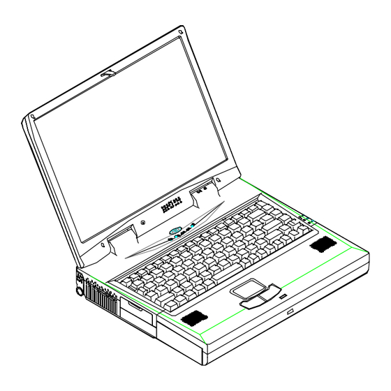
Chapter 3: BIOS Utilities System Status LED Indicators The LED indicators display the system’s operation status. Icon Color Description Green Battery power is used with system turned AC power is used with system turned on. Green Battery is fully charged. Battery is being charged. - Page 22 Microphone LCD Panel Stereo Speakers Power Button Keyboard Trackpad and Buttons Status LED Indicators Figure 1-8...
-
Page 23: Rear View
1-11 Chapter 3: BIOS Utilities ! ! ! ! Rear View AC-in Socket Plug the AC adapter into this socket for power supply. disconnect, pull the plug (not the cord) directly back. Security Connector The Security Connector is used to protect your computer from being stolen. - Page 24 External Monitor (CRT) Port This port is used for transmission of the display to an external monitor. Simultaneous display with the LCD panel is available. Dual PS/2 Type Ports A PS/2 type mouse and keyboard can be connected to the system using these ports.
-
Page 25: Right-Side View
1-13 Chapter 3: BIOS Utilities ! ! ! ! Right-Side View PC Card Sockets One Type III or two Type II PC cards can be used. Both sockets will expand the system capabilities when a PC card is inserted. To eject the PC card, press the appropriate eject button (Figure 2-15). - Page 26 Ventilation The computer vents were designed to help dissipate system’s heat produced during normal operation. Do not block or obstruct vents while DeskNote ™ is in use. Right-side Stand Move this stand (together with the left one) to adjust the typing angle.
-
Page 27: Left-Side View
1-15 Chapter 3: BIOS Utilities ! ! ! ! Left-Side View 5.25” CD-ROM Drive The 5.25” IDE CD-ROM module is designed to be removable. The eject button is located in the middle of the front cover of the CD-ROM drive. Pressing it will release the CD tray. Infrared The system adopts infrared technology as the interface for simple, fast and convenient data exchange from the computer to an infrared-... -
Page 28: Left-Side Stand
Left-side Stand Move this stand (together with the right one) to adjust the typing angle. If a high speed CPU is installed on the system, erecting the stands on both sides will be necessary for heat dissipation during operation (Figure 1-14). CD-ROM Drive Infrared Figure 1-13... -
Page 29: Chapter 2 : Operation
2-17 Chapter 3: BIOS Utilities Chapter 2 : Operation Your EUROCOM 8500 DeskNote has many advanced features to help you with your computer work. This chapter describes each of the computer’s hardware features and shows you how to use them. -
Page 30: Upgrading Processor Module
! ! ! ! Upgrading Processor Module on EUROCOM 8500P/3 DeskNote™ The DeskNote computer features the structure of Intel’s Mobile Module (MMC2). The Processor Module incorporates an Intel Pentium Mobile processor, secondary cache, and the Intel PCI set “Northbridge” system controller, voltage regulator, and thermal sensor on a single printed circuit board. -
Page 31: Replacing Processor Module
2-19 Chapter 3: BIOS Utilities Replacing Processor Module Remove all power sources (AC power and battery). Turn the computer over. Remove the CPU cover. Remove the screws that fasten the heat sink mounted on the Processor Module. Carefully detach the Processor Module from the mainboard (Figure 2- CPU Cover Heat Sink and Fan Processor Module... -
Page 32: Upgrading Processor Module
! ! ! ! Upgrading Processor Module on DeskNote 8500C Replacing Processor Module Remove all power sources (AC power and battery). Turn the computer over. Remove the CPU cover. Remove the screws that fasten the heat sink mounted on the Processor Module. - Page 33 2-21 Chapter 3: BIOS Utilities CPU Cover Figure 2-1.2 Figure 2-1.3...
-
Page 34: Reinstalling Heat Sink
Reinstalling Heat Sink Reinstall the CPU in the reverse order of removal. Make sure that the heat sink cable is properly installed. (Figure 2-2) Figure 2-2... -
Page 35: Setting Dip Switch
2-23 Chapter 3: BIOS Utilities ! ! ! ! Setting DIP Switch Remove the keyboard to reveal the system’s mainboard. Locate the DIPSwitch (SW1) to set the correct configuration for the following purpose: Flash ROM BIOS update To upgrade your computer, you need to keep up with the latest system BIOS. - Page 36 Figure 2-3 Figure 2-4...
-
Page 37: Expanding Memory
! ! ! ! Expanding Memory The EUROCOM 8500P/C DeskNote has three memory sockets for different RAM modules to expand the memory up to 384MB * EUROCOM 8500P3 DeskNote has two memory sockets for up to 256MB of RAM. The RAM modules should be 144-pin SODIMM (Small Outline Dual In-line Memory Module) type. -
Page 38: Accessing The Memory Sockets
Accessing the Memory Sockets Turn the system power off. Press the two keyboard latches to elevate the keyboard from its normal position (Figure 2-3). Carefully lift the keyboard assembly out to expose the mainboard. Locate the memory sockets (Figure 2-5). Note: The memory socket Bank 1 is a reverse type, make sure you install the memory module with reverse side to fit its connector. -
Page 39: Installing Memory Module
2-27 Chapter 3: BIOS Utilities Installing Memory Module Follow the steps below to install the memory module: Turn the system power off. Press the two keyboard latches to elevate the keyboard from its normal position (Figure 2-3). Carefully lift the keyboard assembly out to expose the mainboard. Locate the memory sockets (Figure 2-5). -
Page 40: Removing Memory Module
Removing Memory Module Turn the system power off. Press the two keyboard latches to elevate the keyboard from its normal position (Figure 2-3). Carefully lift the keyboard assembly out to expose the mainboard. Locate the memory sockets (Figure 2-5). Gently pull the two latches outward on both ends of the module. The module will pop up (Figure 2-7). -
Page 41: Using Hard Disk Drive
2-29 Chapter 3: BIOS Utilities ! ! ! ! Using Hard Disk Drive The hard disk drive is mounted in a removable case and can be taken out to accommodate other 2.5” IDE hard disk drives with a height of 12.7mm. The system supports drives with 2.0 GB capacities through the Logical Block Addressing (LBA) mode. -
Page 42: Replacing Hard Disk Drive
Replacing Hard Disk Drive The hard disk drive is contained in a case. To take the hard disk drive out of the case and replace with another one, you need to remove the two screws on each side of the case (Figure 2-9). The location of the two screws may be varied depending on different types of hard disk model. -
Page 43: Using Floppy Disk Drive
2-31 Chapter 3: BIOS Utilities ! ! ! ! Using Floppy Disk Drive The DeskNote computer comes standard with a 1.44MB, 3.5” floppy disk drive module. It is labeled drive A: and may be used as a boot device if properly set. -
Page 44: Replacing Floppy Disk Drive
Replacing Floppy Disk Drive Turn the system power off. Turn the computer over. Locate the Floppy Disk Drive latch. Press the latch in the direction indicated and take the floppy disk drive out of the computer (Figure 2-11). Insert the replacement drive (2.5”/3.0” secondary HDD or 100MB Zip drive) firmly into the computer. -
Page 45: Using Cd-Rom
2-33 Chapter 3: BIOS Utilities ! ! ! ! Using CD-ROM The EUROCOM DeskNote computer comes standard with a removable 5.25” CD-ROM module. It is labeled drive D: and may be used as a boot device if properly set. To insert a CD, press the Eject Button and place the CD into the Disc Tray with label-side facing up. -
Page 46: Removing Cd-Rom Module
Removing CD-ROM Module Turn the system power off. Turn the computer over. Locate the CD-ROM latch. Press the latch in the direction indicated and take the CD-ROM module out of the computer (Figure 2-13). Figure 2-13... -
Page 47: Loading Compact Discs
2-35 Chapter 3: BIOS Utilities Loading Compact Discs Turn on the power. Press the CD-ROM eject button; the disc tray will pop out partially. Pull the disc tray out. Carefully load the CD into the disc tray with label-side facing up. Press it gently to ensure it fits into the place (Figure 2-14). -
Page 48: Handling Of Compact Discs
Handling of Compact Discs Proper handling of your CDs will prevent them from being damaged and ensure the accessibility of data stored in them. Hold the CD by the edges; do not touch the surface of the disc. Use clean, soft, and dry cloth to remove dust or fingerprints. Do not use pen to write on the surface. -
Page 49: Using Pc Card Sockets
2-37 Chapter 3: BIOS Utilities ! ! ! ! Using PC Card Sockets The computer provides system expansion capabilities with two PC card sockets (previously referred to as PCMCIA). PC cards to be inserted can be LAN, fax/modem, communication devices, or expanded memory. Both sockets support 5V/3.3V 16-bit PC cards and 3.3V 32-bit PC cards (referred to as CardBus). -
Page 50: Inserting Pc Cards
Inserting PC Cards Open the access door (Figure 2-16). Align the PC card with the slot and push it in firmly until it locks into the place (Figure 2-17). Figure 2-16 Figure 2-17 Removing PC Cards To remove a PC card, press the appropriate eject button to eject the card from its slot. -
Page 51: Using Hot Keys
2-39 Chapter 3: BIOS Utilities ! ! ! ! Using Hot Keys Located on the bottom-left edge of the keyboard layout is a colored Fn key. The Fn key function allows you to change operational features instantly. When you use the following functions, press and hold the Fn key; then press the appropriate function key (Figure 2-18). -
Page 52: Windows 95 Special Keys
Windows 95 Special Keys The keyboard provides two keys that have special functions in Windows This key has the same functions as the secondary mouse does. This key activates the Windows 95 Start menu. Figure 2-18... -
Page 53: Using Numeric Keypad
2-41 Chapter 3: BIOS Utilities ! ! ! ! Using Numeric Keypad The computer features a 102-key keyboard with an integrated numeric keypad for easy numeric data input (Figure 2-19). Figure 2-19... -
Page 54: Using Power Management
! ! ! ! Using Power Management The system provides you with various modes to manage its power consumption while maintaining system performance. Please refer to Chapter 3: BIOS Utilities, System Configuration Utility, Power Menu for more information. Advanced Power Management (APM 1.2) The system provides built-in Advanced Power Management (APM 1.2) support to reduce power consumption. -
Page 55: Suspend And Resume
2-43 Chapter 3: BIOS Utilities Suspend and Resume When at extremely low power, you can enter suspend mode to save power. In suspend mode, all tasks are stopped and stored in memory to save power. The system features two levels of suspend mode: Powered-On- Suspend (POS) mode and Suspend-To-Disk (STD) mode. -
Page 56: Suspend To Disk (Std)
Suspend To Disk (STD) Suspend to Disk is a 0-volt suspend mode for system power management. STD mode saves the maximum power but takes the longest time to return to full operation. Use your operation system’s FDISK program to delete all partitions of the hard disk if any already exist on the target drive. -
Page 57: Attaching Peripheral Devices
2-45 Chapter 3: BIOS Utilities ! ! ! ! Attaching Peripheral Devices To extend the computer’s functions, you can attach the following peripheral devices to the computer through the ports or jacks on the rear panel of computer. Attaching a Security Lock The security lock is equipped to protect your computer from being stolen. -
Page 58: Attaching A Parallel Printer
Attaching a Parallel Printer You may connect any standard Centronics parallel printer to your computer through the parallel port. Turn the system power off. Connect the cable to the parallel port on the rear of the computer. Tighten the screws that fasten the cable to the parallel port (Figure 2- 21). -
Page 59: Attaching A Tv Set
2-47 Chapter 3: BIOS Utilities Attaching a TV Set The S-Video jack on the rear panel of the computer is used for transmitting video signals to a TV set. You may need to select the video standard for video display. Enter the System Configuration Utility (SCU), Components Menu to specify the appropriate TV mode. -
Page 60: Attaching A Video Input Device
Attaching a Video Input Device The RCA jack on the rear panel of the computer allows analog composite signal input from external video devices. Attach the device as shown below (Figure 2-23). Figure 2-23... -
Page 61: Attaching A Usb-Compatible Device
2-49 Chapter 3: BIOS Utilities Attaching a USB-compatible Device The computer provides dual USB ports for connection of a USB-compatible keyboard, mouse, or other devices. Attach the device as shown below (Figure 2-24). Figure 2-24... -
Page 62: Attaching A Serial Mouse
Attaching a Serial Mouse The serial port features a 9-pin connector. You can connect any serial device such as a mouse to this port. Turn the system power off. Connect the cable to the serial port on the rear of the computer. Tighten the screws that fasten the cable to the serial port (Figure 2- 25). -
Page 63: Attaching An External Monitor (Crt)
2-51 Chapter 3: BIOS Utilities Attaching an External Monitor (CRT) The computer is capable of displaying not only on the LCD, but also on the XGA compatible displays attached to the computer. Information can be displayed on both the LCD and the external monitor simultaneously. Enter the System Configuration Utility (SCU) to select the appropriate parameters or use the Fn + F6 keys (refer to Chapter 2, Using Hot Keys). -
Page 64: Attaching A Ps/2 Keyboard Or Mouse
Attaching a PS/2 Keyboard or Mouse The computer can be operated with a PS/2 keyboard or mouse attached by means of the PS/2 transfer cable. Attach the external keyboard or mouse as shown below (Figure 2-27). Both PS/2 type ports on the rear panel of the computer can be used for the connection of a PS/2 keyboard and mouse. -
Page 65: Attaching A Digital Camera
2-53 Chapter 3: BIOS Utilities Attaching a Digital Camera A digital camera can be connected to the computer through the 1394 port. However, not every type or brand of digital camera can be connected to the computer. Choose the camera that comes with a specially designed plug for 1394 port (Figure 2-28). -
Page 66: Chapter 3 : Bios Utilities
Chapter 3 : BIOS Utilities This chapter provides you with the information of Power On Self-Test (POST) and shows you how to configure the system parameters using the System Configuration Utility (SCU). Power on Self Test (POST) POST Message: Normal Operation POST Message: Error Detected System Configuration Utility (SCU) Information in the SCU... -
Page 67: Power On Self Test (Post)
3-55 Chapter 3: BIOS Utilities ! ! ! ! Power on Self Test (POST) The system BIOS (Basic Input/Output System) performs a series of Power On Self-Test (POST) on system memory and key computer components every time the computer is turned on. If an error exists, the POST routine may halt execution (depending on the problem). -
Page 68: Post Message: Error Detected
POST Message: Error Detected If an error is detected, you will see the following WARNING message. You may press F1 key to continue, or press the Ctrl-Alt-S keys simultaneously to enter the System Configuration Utility. SystemSoft MobilePRO BIOS Version 1.01 (2482-00) Copyright 1983-1996 SystemSoft Corp. -
Page 69: System Configuration Utility
3-57 Chapter 3: BIOS Utilities ! ! ! ! System Configuration Utility The System Configuration Utility (SCU) is a ROM-based configuration utility that displays the system’s configuration status and provides users with a tool to set their system parameters. The settings are stored in non-volatile battery-backed CMOS RAM which saves the information even when the power is turned off, and retains it when the system is turned on again Information in the System Configuration Utility... -
Page 70: Initiating The System Configuration Utility
Initiating the System Configuration Utility The System Configuration Utility (SCU) can be accessed when pressing the Ctrl, Alt, and S keys simultaneously. <CTRL-ALT-S> to enter System Configuration Utility The above message only lasts seconds. If you miss it, the computer will initiate the boot process. -
Page 71: Working With The Menu Bar
3-59 Chapter 3: BIOS Utilities Working with the Menu Bar After entering the SCU, you may use the following keys to work with the menu bar. Keys Action Description Activate menus Activate the System Configuration Utility. Select menu Move to a menu bar Left arrow ( ) item. -
Page 72: Working With The Pull-Down Menu
Working with the Pull-down Menu When the desired menu bar item is highlighted, press the Enter key to enter the pull-down menu for values setting. You may use the following keys to work with the pull-down menu. Keys Action Description Select pull-down menu Move to the next pull- Down arrow ( ) -
Page 73: Features Of The System Configuration Utility
3-61 Chapter 3: BIOS Utilities Features of the System Configuration Utility Startup Menu Item Setting/Option Function Date and Time Day/Month/Year Set the current date Hour/Minute/Second and time. Fast Boot Enable Initialize quickly boot the system in a seconds skipping certain diagnostic tests. - Page 74 Item Setting/Option Function Enable Power Enable Enable or Disable Power On Beep Disable On Beep. Boot Password Enter Power-On Set password for booting Password computer. Users are authorized to start the Enter Power-On system after entering Password correct password. Verify Power-On Password Enable...
-
Page 75: Memory Menu
3-63 Chapter 3: BIOS Utilities Memory Menu Item Setting/Option Function Cache Disabled Disable processor’s internal Systems Cache cache. Write Back Enable Processor’s internal write-back cache. Disabled Disable the L2 cache controller. Cache Write Back Enable the LS write-back cache. BIOS Cached The process of shadowing copies Shadow... -
Page 76: Disks Menu
Disks Menu Item Setting/Option Function Diskette Drive A None Specify the drive types Drives for the diskette drive A. 1.44 Mb 2.88 Mb Primary HDD Drive Enabled Enable enhanced Settings settings. PIO Mode CD-ROM Drive Enabled DVD-ROM / PIO Mode 3rd HDD LS120 /ZIP/ Drive Enabled... -
Page 77: Components Menu
3-65 Chapter 3: BIOS Utilities Components Menu Item Setting/Option Function COM A I/O None Specify the COM A Ports Settings configuration. (COM3 COM1, 3F8, IRQ4 & COM4 Only for DOS COM2, 2F8, IRQ3 mode and Non-PnP COM3, 3E8, IRQ10 OS.) COM4, 2E8, IRQ11 COM B I/O None... - Page 78 Item Setting/Option Function PS/2 Mouse Enable Enable system’s Port trackpad or an external PS/2 mouse. Disable Disable the trackpad or PS/2 mouse external mouse connected to COM A port. Microsoft Enable Support PS/2 mouse Intellimouse with the wheel button. Support Disable Do not support PS/2 mouse with the wheel...
- Page 79 3-67 Chapter 3: BIOS Utilities Item Setting/Option Function Modem Port None Specify the Modem Port settings. Port 3E8, IRQ 11 Port 2E8, IRQ 11 Port 3F8, IRQ 11 Port 3E8, IRQ 9 Port 2E8, IRQ 9 Port 3F8, IRQ 9 Port 2F8, IRQ 9 Port 2F8, IRQ 11 Figure 3-5...
-
Page 80: Power Menu
Power Menu Item Setting/Option Function Enable Power Enable Enable/Disable Saving Disable power saving features. Power Enable Enable/Disable Saving power saving to its lowest which results in Disable max. performance but shortest battery life. Medium Power Enable Enable/Disable Saving power saving to its medium which results Disable both... - Page 81 3-69 Chapter 3: BIOS Utilities Item Setting/Option Function Suspend Power Power The power button is switched to Controls Button On/Off turn the system on or off. Function Suspend/ The power button acts as a Resume suspend/resume button switching the system between a working state and the suspend mode.
- Page 82 Item Setting/Option Function Enable Enable Resume the system from STR or MODEM POS mode when a modem ring is Ring detected (which modem should Resume be connected to the serial port). Disable Disable the above. Enable Enable Automatically suspend the system Battery to disk upon a low battery...
-
Page 83: Exit Menu
3-71 Chapter 3: BIOS Utilities Exit Menu Item Function Save and Exit Save the current settings and reboot the system. Exit (No Save) Exit without saving any current changes. Default Settings Restore the default settings (the original ones found in ROM). Restore Settings Restore the current setup settings to the original custom ones. -
Page 85: Chapter 4 : Troubleshooting
Chapter 5: Installing Drivers Chapter 4 : Troubleshoot ing Sometimes your computer has some problems. Before you consult the computer vendor, you can try to solve problems yourself. This chapter provides you with a list of some commonly experienced problems and their possible solutions. -
Page 86: Battery
! ! ! ! Battery Problem: The battery pack can not be charged. Solution 1: The battery pack is exposed to excessively hot and cold environment. Let it restore to normal condition before you use it. Solution 2: The power might be used up. Problem: The battery pack can not be charged and the charge indicator turns off. -
Page 87: Power
Chapter 5: Installing Drivers ! ! ! ! Power Problem: The computer can not boot when the battery pack is not inserted. Solution 1: The power cord is not correctly connected with AC adapter. Make sure the power cord is firmly plugged into grounded outlet and computer. -
Page 88: Floppy Disk Drive
! ! ! ! Floppy Disk Drive Problem: The floppy disk drive can not write data to disk. Solution 1: The floppy is not formatted. Solution 2: The floppy is write-protected. Please cancel the protection. Solution 3: The data is written to incorrect disk drive. Solution 4: The space left on disk is not enough. -
Page 89: Lcd Panel
Chapter 5: Installing Drivers ! ! ! ! LCD Panel Problem: The font is too dark. Solution: The brightness or contrast is not correctly set. Please press Fn+F7 or Fn+F8 key combination (only limited to DSTN panel) to adjust the contrast control, and use Fn+F9 or Fn+F10 to adjust the brightness control. -
Page 90: Memory Module
! ! ! ! Memory Module Problem: The computer can not boot. Solution: The incorrect type of memory module is installed. Problem: The memory capacity is not enough. Solution: The memory is not correctly configured for the application. Problem: The detected memory capacity is not correct. Solution: Some memory module is not correctly installed or not compatible with your computer. -
Page 91: Boot Password
Chapter 5: Installing Drivers ! ! ! ! Boot Password Problem: You forget the boot password. Solution: While forgetting the password, you must unpack the computer and delete the memory. Please ask the vendor for help ! ! ! ! Audio Problem: The audio speaker can not be heard. - Page 92 ! ! ! ! CD-ROM Problem: The compact disk can not be exited. Solution: The compact disk is not correctly placed in the tray. Problem: The compact disk can not be read. Solution 1: The compact disk is not correctly placed in the tray. Solution 2: The compact disk is dirty.
-
Page 93: Printer
Chapter 5: Installing Drivers ! ! ! ! Printer Problem: The printer can not be set up. Solution: The printer power cord is not plugged into or the connector is not correctly connected. Problem: The printer can not work. Solution 1: The printer is not power on. -
Page 94: Chapter 5 : Installing Drivers
Chapter 5 : Installing Driv ers This chapter provides users the step-by-step instructions of installing device drivers and utilities. Information has been designed to suit for the users who has the basic computer knowledge. However, the inexperienced users also can get good help from the instruction. Installing Windows 95 Installing Windows 98 Installing Drivers in Windows 95... -
Page 95: Installing Windows 95
5-11 Chapter 5: Installing Drivers ! ! ! ! Installing Windows 95 Preparation for installing Windows 95: Use a bootable floppy disk to start the system. Run FDISK utility from DOS to create a bootable partition. (See DOS manual for the operation detail.) Format hard disk. - Page 96 remove the disk, then click “OK”. 15. Click “Next” to start copying Windows 95 files to your computer. 16. Click “Finish” to restart Windows 95. 17. On the screen of “Set Up a Printer”, click “Cancel”. Note: Do not install a printer at this time. You will not be able to access the Windows 95 Installation CD until you reboot.
-
Page 97: Installing Windows 98
5-13 Chapter 5: Installing Drivers ! ! ! ! Installing Windows 98 1. Start DOS. 2. Insert the Windows 98 CD-ROM. 3. Type “setup”, then press [Enter]. 4. Follow the instructions on the screen and choose the recommended option. 5. The Windows 98 setup program will check the hard disk drive automatically. -
Page 98: Installing Drivers In Windows 95
! ! ! ! Installing Drivers in Windows 95 Step 1: Installing USB Driver Download “USB supplement path update file” from Microsoft and Intel web site. Run “USB supplement path” to install the driver. Step 2: Installing TXPATCH Driver Locate the driver “[TXPATCH] Intel 82371xb.inf TX” from the CD-ROM. Run “setup.exe”. -
Page 99: Step 4: Installing Audio Driver (1978S M2E)
5-15 Chapter 5: Installing Drivers Step 4: Installing Audio Driver (1978S M2E) Double click “Start”. Select “Setting”. Click “Control Panel”/”System”/”Device Manager”. Select “Other devices”. Remove “Unknown Device”. Click “OK”, then restart the system. After entering into WIN95 system, the program will automatically go to the “Add New Hardware Wizard”... -
Page 100: Step 6: Installing Video-In Driver
Step 6: Installing Video-in Driver Boot the system, press Ctrl + Alt + S to enter SCU system. Select “Components”. Enable “Video In Mode”. Under Windows 95, double click “Start”. Select “Run”. Open the path “D:\video-in\setup.exe. Run “setup.exe” to finish the installation. Step 7: Installing ATI DVD Play Driver (Option) Note: Make sure that you have already successfully installed the VGA Driver,... -
Page 101: Installing Drivers In Windows Nt 4.0
5-17 Chapter 5: Installing Drivers ! ! ! ! Installing Drivers in Windows NT 4.0 Note: After installing Windows NT4.0, please install Service Pack3 to enhance the function. Download the latest Service Pack3 version from the Microsoft web site. Step 1: Installing VGA Driver Double click “Start”. -
Page 102: Installing Drivers In Windows 98
! ! ! ! Installing Drivers in Windows 98 Step 1: Installing VGA Driver Double click “Start”. Select “Run”. Open the path “D:\WIN9X\setup.exe. Run “setup.exe” to finish installation. Note: When ATI VGA driver has existed in WIN95 system, click “Start”, select “Run”, open the path “atiuinst-clean”, and then double-click “OK”... -
Page 103: Step 3: Installing Pcmcia Driver
5-19 Chapter 5: Installing Drivers Step 3: Installing PCMCIA Driver Click “Start”/”Control Panel”/”System”. Remove PCMCIA. Delete the two sub-directories [Generic CardBus Controller]. Switch to DOS. Copy the file [PCMCIA.inf] to the directory [C:\windows\inf]. Restart Win98 system. Step 4: Installing Video-in Driver Boot the system. - Page 105 Appendix B--I/O Port Pin Assignments Appendix A: Specifications This following are the features and specifications of the EUROCOM DeskNote computer. Processor EUROCOM 8500P DeskNote ™ 233/266/300/333/366/400 MHz Mobile Pentium II processors Intel Mobile Module Connector II Structure (MMC2) 66 MHz CPU Bus Clock Processor EUROCOM 8500P3 DeskNote ™...
- Page 106 Appendix B--I/O Port Pin Assignments System BIOS 256KB Flash ROM Plug and Play 1.0a Display 15.1”/15.0” TFT XGA LCD panel 8MB display memory SGRAM type (100MHz) Support VPM 1.10 (Zoomed Video Port) DVD S-Video TV out Tri-view™ for a triple, TV, CRT & LCD. Storage 3.5”...
- Page 107 Appendix B--I/O Port Pin Assignments Audio Sound-Blaster Pro™ version 3.01 compatible 3D stereo sound system Stereo full duplex support MPEG-2 module Built-in microphone Built-in 2 watts speakers x 2 PC Card Sockets Support CardBus (PC Card95) Support Zoom Video Port (Socket A) Two Type II PC cards or one Type III PC card Input/Output Built-in trackpad (PS/2)
- Page 108 Lithium-Ion Battery/Lithium-Ion Smart Battery Size & Weight 358mm(w)x280mm(d)x50mm(h) 4.2kg (with Lithium-Ion battery) Keyboard 102 keys Win95 keyboard include numeric keypad. BIOS One 256KB Flash ROM. Systemsoft BIOS with Smart Battery, Plug and Play, ACPI. Thank you for purchasing your Eurocom 8500 DeskNote VIII...
Need help?
Do you have a question about the 8500-C DeskNote and is the answer not in the manual?
Questions and answers