Table of Contents
Advertisement
Advertisement
Table of Contents

Related Manuals for DFI LanParty PRO875B


Summary of Contents for DFI LanParty PRO875B
- Page 1 Rev. B+ System Board User’s Manual 74820402...
- Page 2 Copyright This publication contains information that is protected by copy- right. No part of it may be reproduced in any form or by any means or used to make any transformation/adaptation without the prior written permission from the copyright holders. This publication is provided for informational purposes only.
-
Page 3: Fcc And Doc Statement On Class B
Battery: • Danger of explosion if battery incorrectly replaced. • Replace only with the same or equivalent type recommend by the manufacturer. • Dispose of used batteries according to the battery manufac- turer’s instructions. Joystick or MIDI port: • Do not use any joystick or MIDI device that requires more than 10A current at 5V DC. - Page 4 Important Configuration and Driver Installation Rules HighPoint RAID IDE Controller By default, the HighPoint RAID IDE controller is enabled. If you are not using this function, make sure to set the “RAID Device Control” field in the Genie BIOS Setting submenu of the Award BIOS to Disabled.
-
Page 5: Table Of Contents
Table of Contents Chapter 1 - Introduction 1.1 Features and Specifications................1.2 Hyper-Threading Technology Functionality Requirements. 1.3 Package Checklist......................Chapter 2 - Hardware Installation System Board Layout ..................System Memory......................CPU............................Jumper Settings......................Rear Panel I/O Ports..................... I/O Connectors......................Chapter 3 - BIOS Setup 3.1 Award BIOS Setup Utility.................. - Page 6 Introduction Appendix A - Enabling the Hyper-Threading T echnology A.1 Enabling the Hyper-Threading Technology........Appendix B - CPU Fan Protection B.1 CPU Fan Protection....................Appendix C - System Error Messages C.1 POST Beep........................C.2 Error Messages......................Appendix D - Troubleshooting D.1 Troubleshooting Checklist................
-
Page 7: Chapter 1 - Introduction
Introduction Chapter 1 - Introduction 1.1 Features and Specifications 1.1.1 Features Chipset • Intel 875P chipset ® ® Intel 82875P Memory Controller Hub (MCH) ® Intel 82801ER I/O Controller Hub (ICH5R) Processor The system board is equipped with Socket 478 for installing one of the following supported processors. - Page 8 Introduction Use PC2100/PC2700 (DDR266/DDR333) with 533MHz FSB CPU Use PC2100 (DDR266) with 400MHz FSB CPU • Supports ECC/non-ECC DIMMs • Supports unbuffered DIMMs Density 128 Mbit 256 Mbit 512 Mbit Density Width SS/DS SS/DS SS/DS SS/DS SS/DS Single/Double SS/DS 128/256MB 64MB/NA 128MB/NA 512/1024MB...
- Page 9 Introduction • Pipelined memory read and write operations that hide memory access latency. • Demultiplexing of address and data on the bus for nearly 100 percent efficiency. Note: AGP 2x and 3.3V AGP cards are not supported. Onboard Audio Features •...
- Page 10 Introduction Compatibility • PCI 2.2 and AC ’97 compliant • Intel AGP version 3.0 ICH5R SATA IDE/RAID Interface Serial ATA is a storage interface that is compliant with SATA 1.0 specification. With speed of up to 1.5Gbps, it improves hard drive performance even in data intensive environments such as audio/ video, consumer electronics and entry-level servers.
- Page 11 Introduction USB Ports The system board supports USB 2.0 and USB 1.1 ports. USB 1.1 suppor ts 12Mb/second bandwidth while USB 2.0 suppor ts 480Mb/second bandwidth providing a marked improvement in device transfer speeds between your computer and a wide range of simultaneously accessible external Plug and Play peripherals.
-
Page 12: System Health Monitor Functions
Introduction I/O Connectors • 2 connectors for 4 additional external USB 2.0/1.1 ports • 1 front audio connector for external line-out and mic-in jacks • 1 connector for an external game/MIDI port • 2 internal audio connectors (CD-in and AUX-in) •... - Page 13 Introduction 1.1.3 Intelligence CPU Fan Protection The CPU Fan Protection function has the capability of monitoring the CPU fan when the system boots. Once it has detected that the CPU fan did not rotate, 5 warning beeps will sound then the sys- tem will automatically power-off.
- Page 14 Introduction Wake-On-LAN This feature allows the network to remotely wake up a Soft Power Down (Soft-Off) PC. It is supported via the onboard LAN port, via a PCI LAN card that uses the PCI PME (Power Manage- ment Event) signal or via a LAN card that uses the Wake-On- LAN connector.
- Page 15 Introduction ACPI The system board is designed to meet the ACPI (Advanced Con- figuration and Power Interface) specification. ACPI has energy sav- ing features that enables PCs to implement Power Management and Plug-and-Play with operating systems that support OS Direct ®...
-
Page 16: Hyper-Threading Technology Functionality Requirements
Introduction 1.2 Hyper-Threading Technology Functionality Requirements Enabling the functionality of Hyper-Threading Technology for your computer system requires ALL of the following platforms. Components: ® ® • CPU - an Intel Pentium 4 Processor with HT Technology ® • Chipset - an Intel chipset that supports HT Technology •... - Page 17 Introduction One case badge One pack of jumper caps (five 2.54mm jumper caps) One “HighPoint 372 N RAID Drivers” diskette One “Intel ICH5R RAID Driver” diskette One “Mainboard Utility” CD One “WinDVD/WinRIP Utility” CD If any of these items are missing or damaged, please contact your dealer or sales representative for assistance.
-
Page 18: Chapter 2 - Hardware Installation
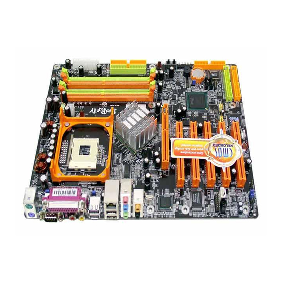
Hardware Installation Chapter 2 - Hardware Installation 2.1 System Board Layout... -
Page 19: System Memory
Hardware Installation Warning: Electrostatic discharge (ESD) can damage your system board, processor, disk drives, add-in boards, and other components. Perform the upgrade instruction procedures described at an ESD workstation only. If such a station is not available, you can provide some ESD protection by wearing an antistatic wrist strap and attaching it to a metal part of the system chassis. -
Page 20: Hardware Installation
Hardware Installation The system board supports the following memory interface. Single Channel (SC) Data will be accessed in chunks of 64 bits (8B) from the memory channels. Virtual Single Channel (VSC) If both channels are populated with different memory configurations, the MCH defaults to Virtual Single Channel. - Page 21 Hardware Installation The table below lists the various optimal operating modes that should be configured for the memory channel operation. DDR 3 DDR 4 Config DDR 1 DDR 2 No memory Single channel A Single channel A Single channel A Single channel B Single channel B Single channel B...
- Page 22 Hardware Installation DDR 3 DDR 4 DDR 1 DDR 2 Config P(*)(2,4) P(*)(2,4) Dynamic Mode Addressing P(*)(1,3) P(*)(1,3) Dynamic Mode Addressing P(*)(1,3) P(*)(2,4) P(*)(1,3) P(*)(2,4) Dynamic Mode Addressing P(*)(2,4) P(*)(2,4) Dynamic Mode Addressing P(*)(1,3) P(*)(1,3) Dynamic Mode Addressing P(*)(1,3) P(*)(2,4) P(*)(1,3) P(*)(2,4) Dynamic Mode Addressing...
-
Page 23: Installing The Dim Module
Hardware Installation 2.2.1 Installing the DIM Module A DIM module simply snaps into a DIMM socket on the system board. Pin 1 of the DIM module must correspond with Pin 1 of the socket. Notch Pin 1 1. Pull the “tabs” which are at the ends of the socket to the side. 2. -
Page 24: Cpu
Hardware Installation 2.3 CPU 2.3.1 Overview The system board is equipped with a surface mount 478-pin CPU socket. This socket is exclusively designed for installing an Intel processor. 2.3.2 Installing the CPU 1. Locate Socket 478 on the system board. 2. - Page 25 Hardware Installation 3. Position the CPU above the socket then align the gold mark on the corner of the CPU (designated as pin 1) with pin 1 of the socket. Important: Handle the CPU by its edges and avoid touching the pins. Gold mark Pin 1 4.
-
Page 26: Installing The Fan And Heat Sink
Hardware Installation 5. Once the CPU is in place, push down the lever to lock the socket. The lever should click on the side tab to indicate that the CPU is completely secured in the socket. 2.3.3 Installing the Fan and Heat Sink The CPU must be kept cool by using a CPU fan with heatsink. - Page 27 Hardware Installation 1. The system board comes with the retention module base already installed. Retention Retention hole hole Retention Retention hole hole Retention module base 2. Position the fan / heat sink and retention mechanism assembly on the CPU, then align and snap the retention legs’ hooks to the retention holes at the 4 corners of the retention module base.
- Page 28 Hardware Installation 3. The retention levers at this time remains unlocked as shown in the illustration below. Retention lever Retention lever 4. Move the retention levers to their opposite directions then push them down. This will secure the fan / heat sink and retention mechanism assembly to the retention module base.
-
Page 29: Jumper Settings
Hardware Installation 2.4 Jumper Settings 2.4.1 Jumper Settings for Clearing CMOS Data 1-2 On: Normal 2-3 On: (default) Clear CMOS Data If you encounter the following, a) CMOS data becomes corrupted. b) You forgot the supervisor or user password. c) You are unable to boot-up the computer system because the processor’s ratio/clock was incorrectly set in the BIOS. - Page 30 Hardware Installation 4. After powering-on the system, press <Del> to enter the main menu of the BIOS. 5. Select the Genie BIOS Setting submenu and press <Enter>. 6. Set the “CPU Clock” or “CPU Clock Ratio” field to its default setting or an appropriate bus clock or frequency ratio.
- Page 31 Hardware Installation 2.4.2 Jumper Settings for Wake-On-Keyboard/Wake-On- Mouse 1-2 On: Disabled 2-3 On: Enabled (default) This Wake-On-Keyboard/Mouse function allows you to use the PS/2 keyboard or PS/2 mouse to wake up a system from the S3/S4/S5 state. To enable this function, set JP1 pins 2 and 3 to On. BIOS Setting: “Keyboard/Mouse Power On”...
-
Page 32: Jumper Settings For Wake-On-Usb Keyboard
Hardware Installation 2.4.3 Jumper Settings for Wake-On-USB Keyboard USB 1-4 (JP2) 2-3 On: Enabled 1-2 On: Disabled (default) USB 5-8 (JP6) 1-2 On: Disabled 2-3 On: Enabled (default) The Wake-On-USB Keyboard function allows you to use a USB keyboard to wake up a system from the S3 (STR - Suspend To RAM) state. -
Page 33: Rear Panel I/O Ports
Hardware Installation 2.5 Rear Panel I/O Ports RJ45 Mic-in PS/2 Line-in Parallel Mouse USB 2 Center/Bass Rear out PS/2 S/PDIF-in USB 1 USB 3-4 S/PDIF-out Line-out The rear panel I/O ports consist of the following: • PS/2 mouse port • PS/2 keyboard port •... - Page 34 Hardware Installation 2.5.1 PS/2 Mouse and PS/2 Keyboard Ports PS/2 Mouse PS/2 Keyboard The system board is equipped with an onboard PS/2 mouse (Green) and PS/2 keyboard (Purple) ports - both at location CN1 of the system board. The PS/2 mouse port uses IRQ12. If a mouse is not connected to this port, the system will reserve IRQ12 for other expansion cards.
-
Page 35: Serial Ports
Hardware Installation 2.5.2 Serial Ports The system board is equipped with an onboard serial port (Teal/ Turquoise) at location CN3 of the system board. It is a RS-232C asynchronous communication por t with 16C550A-compatible UART that can be used with a modem, serial printer, remote display terminal or other serial devices. -
Page 36: Parallel Port
Hardware Installation 2.5.3 Parallel Port Parallel The system board has a standard parallel port (Burgundy) at location CN5 for interfacing your PC to a parallel printer. It supports SPP, ECP and EPP. Setting Function Allows normal speed operation but (Standard Parallel Port) in one direction only. - Page 37 Hardware Installation 2.5.4 S/PDIF-in/out Jacks S/PDIF-in S/PDIF-out SPDIF out SPDIF in The system board is equipped with an onboard S/PDIF-in RCA jack (red) and a S/PDIF-out RCA jack (yellow) at locations CN20 and CN21 respectively. The S/PDIF connector at location J4 is for optical S/PDIF cable connection.
-
Page 38: Universal Serial Bus Ports
Hardware Installation 2.5.5 Universal Serial Bus Ports USB 2 USB 1 USB 4 USB 3 USB 7-8 USB 5-6 The system board supports 8 USB 2.0/1.1 ports. USB allows data exchange between your computer and a wide range of simultaneously accessible external Plug and Play peripherals. Four onboard USB 2.0/1.1 ports (Black) are at locations CN7 and CN8 of the system board. - Page 39 Hardware Installation BIOS Setting Enable or disable the onboard USB in the Integrated Peripherals submenu (“Intel OnChip PCI Device” field) of the BIOS. Refer to chapter 3 for more information. Driver Installation You may need to install the proper drivers in your operating system to use the USB device.
-
Page 40: Rj45 Lan Port
Hardware Installation 2.5.6 RJ45 LAN Port RJ45 LAN The system board is equipped with an onboard RJ45 LAN port at location CN8 of the system board. It allows the system board to connect to a local area network by means of a network hub. BIOS Setting Enable or disable the onboard LAN in the Genie BIOS Setting submenu of the BIOS. - Page 41 Hardware Installation 2.5.7 Audio Mic-in Line-in Line-out Center/Bass Rear out Front audio Mic-in, Line-in and Line-out The mic-in, line-in and line-out jacks are at location CN9 of the system board. A jack is a one-hole connecting interface for insert- ing a plug. •...
- Page 42 Hardware Installation • Line-out Jack (Lime) This jack is used to connect external speakers for audio output from the system board. Using this jack disables the front au- dio’s line-out function. Center/Bass and Rear Out Jacks Center/Bass and Rear Out Jacks (CN22) support 4 audio output signals: center channel, subwoofer, rear right channel and rear left channel.
-
Page 43: I/O Connectors
Hardware Installation 2.6 I/O Connectors 2.6.1 Game/MIDI Port The system board is equipped with a 15-pin connector at location J8 for connecting an external game/MIDI port. One card-edge bracket, mounted with a game/MIDI port cable, is provided with the system board. Install the card-edge bracket to the system chassis then connect the game/MIDI port cable to connector J8. -
Page 44: Internal Audio Connectors
Hardware Installation 2.6.2 Internal Audio Connectors Ground Ground Ground Ground Left audio Right audio Left audio Right audio channel channel channel channel CD-in AUX-in The CD-in (J10) and AUX-in (J11) connectors are used to receive audio from a CD-ROM drive, TV tuner or MPEG card. -
Page 45: Floppy Disk Drive Connector
Hardware Installation 2.6.3 Floppy Disk Drive Connector The system board is equipped with a shrouded floppy disk drive connector that supports two standard floppy disk drives. To prevent improper floppy cable installation, the shrouded floppy disk header has a keying mechanism. The 34-pin connector on the floppy cable can be placed into the header only if pin 1 of the connector is aligned with pin 1 of the header. -
Page 46: Serial Ata Connectors
Hardware Installation 2.64 Serial ATA Connectors SATA 2 SATA 1 Two Serial ATA cables are provided with the system board. Connect one end of the cable to J6 (SATA 2) or J12 (SATA 1) and the other end to your serial ATA device. BIOS Setting Configure the Serial ATA drives in the Integrated Peripherals submenu (“Intel OnChip IDE Device”... - Page 47 Hardware Installation 2.6.5 RAID IDE Disk Drive Connectors RAID 2 RAID 1 The HighPoint RAID controller allows configuring RAID on hard drives connected to the RAID IDE connectors. It supports RAID levels 0, 1, 0+1 and 1.5. RAID Level Minimum Number of Drives RAID 0 RAID 1 RAID 0+1...
- Page 48 Hardware Installation Drives in an array must be identical. If striping for performance, use two new drives. If mirroring for protection, you can use two new drives or use an existing drive and a new drive (the new drive must be the same size or larger than the existing drive).
-
Page 49: Ide Disk Drive Connector
Hardware Installation 2.6.6 IDE Disk Drive Connector IDE 1 IDE 2 IDE 2 IDE 1 The system board is equipped with two shrouded PCI IDE headers that will interface four Enhanced IDE (Integrated Drive Electronics) disk drives. To prevent improper IDE cable installation, each shrouded PCI IDE header has a keying mechanism. - Page 50 Hardware Installation Note: Refer to your disk drive user’s manual for information about selecting proper drive switch settings. Adding a Second IDE Disk Drive When using two IDE drives, one must be set as the master and the other as the slave. Follow the instructions provided by the drive manufacturer for setting the jumpers and/or switches on the drives.
-
Page 51: Irda Connector
Hardware Installation 2.6.7 IrDA Connector IRRX N. C. Ground IRTX Connect your IrDA cable to connector J9 on the system board. Note: The sequence of the pin functions on some IrDA cable may be reversed from the pin function defined on the system board. Make sure to connect the cable to the IrDA connector according to their pin functions. -
Page 52: Cooling Fan Connectors
Hardware Installation 2.6.8 Cooling Fan Connectors Power Ground Sense On/Off Power Sense CPU fan Chip fan Ground Power N. C. Chassis fan Power On/Off Sense Second fan Connect the CPU fan’s cable connector to the CPU fan connec- tor (J1) on the system board. Connect the Intel 875P fan’s cable connector to the Chip fan connector (J4) on the system board. - Page 53 Hardware Installation 2.6.9 Wake-On-LAN Connector Ground +5VSB Your LAN card package should include a cable. Connect one end of the cable to the wakeup header on the card and the other end to location J21 on the system board. The network will detect Magic Packet and assert a wakeup signal to power-up the system.
- Page 54 Hardware Installation 2.6.10 LEDs DIMM Standby Power LED Diagnostic LED PCI Standby Power LED DIMM Standby Power LED This LED will turn red when the system’s power is on or when it is in the Suspend state (Power On Suspend or Suspend to RAM). It will not light when the system is in the Soft-Off state.
- Page 55 Hardware Installation LED 1 LED 2 LED 3 LED 4 Ear ly program chipset register before POST. Testing memory presence. Detecting memory size. No memory present. Programming DRAM timing register. Calculating DRAM size variable including row, column and bank. Initializing JEDEC of current DRAM row.
-
Page 56: Power Connectors
Hardware Installation 2.6.11 Power Connectors 3.3V 3.3V -12V 3.3V Ground Ground PS-ON Ground Ground Ground Ground Ground PW-OK 5VSB +12V +12V Ground Ground +12V We recommend that you use a power supply that complies with the ATX12V Power Supply Design Guide Version 1.1. An ATX12V power supply has a standard 20-pin ATX main power connector and a 4-pin +12V power connector that must be inserted onto CN2 and CN4 connectors respectively. -
Page 57: Front Panel Connectors
Hardware Installation 2.6.12 Front Panel Connectors 2019 SPEAKER RESET ATX-SW HD-LED PWR-LED HD-LED: Primary/Secondary IDE LED This LED will light when the hard drive is being accessed. RESET: Reset Switch This switch allows you to reboot without having to power off the system thus prolonging the life of the power supply or system. - Page 58 Hardware Installation PWR-LED: Power/Standby LED When the system’s power is on, this LED will light. When the system is in the S1 (POS - Power On Suspend) state, it will blink every second. When the system is in the S3 (STR - Suspend To RAM) state, it will blink every second.
- Page 59 Hardware Installation 2.6.13 EZ Touch Switches (Power Switch and Reset Switch) Power Switch Reset Switch The presence of the power switch and reset switch on the sys- tem board are user-friendly especially to DIY users. They provide convenience in powering on and/or resetting the system while fine tuning the system board before it is installed into the system chassis.
-
Page 60: Chapter 3 - Bios Setup
BIOS Setup Chapter 3 - BIOS Setup 3.1 Award BIOS Setup Utility The Basic Input/Output System (BIOS) is a program that takes care of the basic level of communication between the processor and peripherals. In addition, the BIOS also contains codes for vari- ous advanced features found in this system board. -
Page 61: Standard Cmos Features
BIOS Setup 3.1.1 Standard CMOS Features Use the arrow keys to highlight “Standard CMOS Features” and press <Enter>. A screen similar to the one on the next page will appear. The settings on the screen are for reference only. Your version may not be identical to this one. -
Page 62: Bios Setup
BIOS Setup 3.1.1.3 IDE Channel 0 Master, IDE Channel 0 Slave, IDE Channel 1 Master and IDE Channel 1 Slave Move the cursor to the “IDE Channel 0 Master”, “IDE Channel 0 Slave”, “IDE Channel 1 Master” or “IDE Channel 1 Slave” field, then press <Enter>. - Page 63 BIOS Setup Capacity Displays the approximate capacity of the disk drive. Usually the size is slightly greater than the size of a formatted disk given by a disk checking program. Cylinder This field displays the number of cylinders. Head This field displays the number of read/write heads. Precomp This field displays the number of cylinders at which to change the write timing.
- Page 64 BIOS Setup 3.1.1.5 Video This field selects the type of video adapter used for the primary system monitor. Although secondary monitors are supported, you do not have to select the type. The default setting is EGA/VGA. EGA/VGA Enhanced Graphics Adapter/Video Graphics Array. For EGA, VGA, SVGA and PGA monitor adapters.
-
Page 65: Advanced Bios Features
BIOS Setup 3.1.1.9 Total Memory Displays the total memory available in the system. 3.1.2 Advanced BIOS Features The Advanced BIOS Features allows you to configure your sys- tem for basic operation. Some entries are defaults required by the system board, while others, if enabled, will improve the per- formance of your system or let you set some features according to your preference. - Page 66 BIOS Setup 3.1.2.2 CPU Feature This field is used to configure the CPU that is installed on the system board. 3.1.2.3 Hard Disk Boot Priority This field is used to select the boot sequence of the hard drives. Move the cursor to this field then press <Enter>. Use the Up or Down arrow keys to select a device then press <+>...
- Page 67 BIOS Setup 3.1.2.8 RAID or SCSI Card Boot This field is used to select the RAID device you want to boot. High Point RAID The drive connected to the RAID IDE con- nector. ICH5 RAID The drive connected to the SATA connector. PCI SCSI Card The drive connected to the SCSI add-in card that is installed in a PCI slot.
- Page 68 BIOS Setup 3.1.2.12 Boot Up Floppy Seek When enabled, the BIOS will check whether the floppy disk drive installed is 40 or 80 tracks. Note that the BIOS cannot distinguish between 720K, 1.2M, 1.44M and 2.88M drive types as they are all 80 tracks.
- Page 69 BIOS Setup 3.1.2.15 Typematic Rate (Chars/Sec) This field allows you to select the rate at which the keys are accelerated. 3.1.2.16 Typematic Delay (Msec) This field allows you to select the delay between when the key was first depressed and when the acceleration begins. 3.1.2.17 Security Option This field determines when the system will prompt for the pass- word - everytime the system boots or only when you enter the...
- Page 70 BIOS Setup 3.1.2.21 HDD S.M.A.R.T. Capability The system board supports SMART (Self-Monitoring, Analysis and Reporting Technology) hard drives. SMART is a reliability predic- tion technology for ATA/IDE and SCSI drives. The drive will pro- vide sufficient notice to the system or user to backup data prior to the drive’s failure.
-
Page 71: Advanced Chipset Features
BIOS Setup 3.1.3 Advanced Chipset Features The settings on the screen are for reference only. Your version may not be identical to this one. This section gives you functions to configure the system based on the specific features of the chipset. The chipset manages bus speeds and access to system memory resources. - Page 72 BIOS Setup Manual If you want better performance for your system other than the one “by SPD”, select “Manual” then select the best option in the “CAS Latency Time” to “DRAM RAS# Precharge” fields. 3.1.3.2 CAS Latency Time This field is used to select the local memory clock periods. 3.1.3.3 Active to Precharge Delay The options are 5, 6, 7 and 8.
- Page 73 BIOS Setup 3.1.3.8 System BIOS Cacheable When this field is enabled, accesses to the system BIOS ROM addressed at F0000H-FFFFFH are cached, provided that the cache controller is enabled. The larger the range of the Cache RAM, the higher the efficiency of the system. 3.1.3.9 Video BIOS Cacheable As with caching the system BIOS, enabling the Video BIOS cache will allow access to video BIOS addresssed at C0000H to...
-
Page 74: Integrated Peripherals
BIOS Setup 3.1.4 Integrated Peripherals The settings on the screen are for reference only. Your version may not be identical to this one. 3.1.4.1 Intel OnChip IDE Device Move the cursor to this field and press <Enter>. The following screen will appear. The settings on the screen are for reference only. - Page 75 BIOS Setup IDE DMA Transfer Access This field, when Enabled, will enhance the IDE DMA transfer of an IDE hard disk drive. On-Chip Primary PCI IDE and On-Chip Secondary PCI IDE These fields allow you to enable or disable the primary and sec- ondary IDE controller.
- Page 76 BIOS Setup IDE HDD Block Mode Enabled The IDE HDD uses the block mode. The system BIOS will check the hard disk drive for the maxi- mum block size the system can transfer. The block size will depend on the type of hard disk drive. Disabled The IDE HDD uses the standard mode.
- Page 77 BIOS Setup Serial ATA Port1 Mode and Serial ATA Port2 Mode These fields are used to select the master/slave mode of the serial ATA drives. Make sure they do not conflict with the settings of the IDE hard drives.
- Page 78 BIOS Setup 3.1.4.2 Intel OnChip PCI Device Move the cursor to this field and press <Enter>. The following screen will appear. The settings on the screen are for reference only. Your version may not be identical to this one. USB Controller Enabled Enables the onboard USB.
- Page 79 BIOS Setup 3.1.4.3 Onboard Super IO Device Move the cursor to this field and press <Enter>. The following screen will appear. The settings on the screen are for reference only. Your version may not be identical to this one. KBC Input Clock This is used to select the input clock of your keyboard.
- Page 80 BIOS Setup Onboard SIR Select This field is used to select an I/O address for the IrDA device. IR Mode Select This field is used to select the type of IrDA standard supported by your IrDA device. For better transmission of data, your IrDA peripheral device must be within a 30 angle and within a dis- tance of 1 meter.
- Page 81 BIOS Setup Onboard Parallel Port 378/IRQ7, 3BC/IRQ7, 278/IRQ5 Selects the I/O address and IRQ for the onboard parallel port. Disabled Disables the onboard parallel port. Parallel Port Mode The options are SPP, EPP, ECP and ECP+EPP. These apply to a standard specification and will depend on the type and speed of your device.
- Page 82 BIOS Setup Midi Port Address This field is used to select the midi port’s address. If you have selected the midi port’s address, you may select its IRQ in the “Midi Port IRQ” field. Midi Port IRQ This field is used to select the midi port’s IRQ. 3.1.4.4 Init Display First This field is used to select whether to initialize the AGP or PCI first when the system boots.
-
Page 83: Power Management Setup
BIOS Setup 3.1.5 Power Management Setup The Power Management Setup allows you to configure your sys- tem to most effectively save energy. The settings on the screen are for reference only. Your version may not be identical to this one. 3.1.5.1 ACPI Function This function should be enabled only in operating systems that ®... - Page 84 BIOS Setup 3.1.5.3 Run VGABIOS if S3 Resume When this field is set to Auto, the system will initialize the VGA BIOS when it wakes up from the S3 state. This can be configured only if the “ACPI Suspend Type” field is set to “S3(STR)”. 3.1.5.4 Power Management This field allows you to select the type (or degree) of power saving by changing the length of idle time that elapses before the...
- Page 85 BIOS Setup 3.1.5.8 HDD Power Down This is selectable only when the Power Management field is set to User Define. When the system enters the HDD Power Down mode according to the power saving time selected, the hard disk drive will be powered down while all other devices remain ac- tive.
- Page 86 BIOS Setup 3.1.5.12 Resume On LAN If you are using a LAN card that supports the remote wake up function, set this field to Enabled. The will allow the network to remotely wake up a Soft Power Down (Soft-Off) PC. However, if your system is in the Suspend mode, you can wake up the sys- tem only through an IRQ or DMA interrupt.
- Page 87 BIOS Setup 3.1.5.17 Time (hh:mm:ss) Alarm This is used to set the time you would like the system to power- on. If you want the system to power-on everyday as set in the “Date (of Month) Alarm” field, the time set in this field must be later than the time of the RTC set in the Standard CMOS Fea- tures submenu.
- Page 88 BIOS Setup 3.1.5.20 KB Power On Hot Key This field is used to select a function key that you would like to use to power-on the system. 3.1.5.21 PWR Lost Resume State Keep Off When power returns after an AC power failure, the system’s power is off.
- Page 89 BIOS Setup 3.1.6 PnP/PCI Configurations This section describes configuring the PCI bus system. It covers some very technical items and it is strongly recommended that only experienced users should make any changes to the default settings. The settings on the screen are for reference only. Your version may not be identical to this one.
- Page 90 BIOS Setup 3.1.6.4 PCI/VGA Palette Snoop This field determines whether the MPEG ISA/VESA VGA cards can work with PCI/VGA or not. The default value is Disabled. Enabled MPEG ISA/VESA VGA cards work with PCI/VGA. Disabled MPEG ISA/VESA VGA cards does not work with PCI/ VGA.
-
Page 91: Pc Health Status
BIOS Setup 3.1.7 PC Health Status The settings on the screen are for reference only. Your version may not be identical to this one. 3.1.7.1 CPU Fan Protection The CPU Fan Protection function, when enabled, has the capabil- ity of monitoring the CPU fan when the system boots. Once it has detected that the CPU fan did not rotate, 5 warning beeps will sound then the system will automatically power-off. - Page 92 BIOS Setup 3.1.7.4 CPU(V) These fields show the voltage of the processor. 3.1.7.5 +1.5V, +3.3V, +5V, +12V, -12V, VBAT(V) and 5VSB(V) These fields show the output voltage of the power supply. Note: The onboard hardware monitor function is capable of detecting “system health”...
-
Page 93: Genie Bios Setting
BIOS Setup 3.1.8 Genie BIOS Setting The settings on the screen are for reference only. Your version may not be identical to this one. 3.1.8.1 CPU Clock This field provides several options for selecting the external sys- tem bus clock of the processor. The available options allow you to adjust the processor’s bus clock by 1MHz increment. - Page 94 BIOS Setup 3.1.8.3 CPU Clock Now Is This field will show the CPU clock based on the settings in the “CPU Clock” and “CPU Clock Ratio” fields. 3.1.8.4 AGP/PCI/SATA Clock This field is used to select the bus clock of the AGP, PCI and SATA.
- Page 95 BIOS Setup 3.1.8.9 DIMM Voltage Control This field allows you to manually select higher voltage supplied to the DRAM. If you want to use the DRAM’s default voltage, leave this field in its default setting. Important: Although this function is supported, we do not recommend that you use a higher voltage because unstable current may be sup- plied to the system board causing damage.
-
Page 96: Cmos Reloaded
BIOS Setup 3.1.9 CMOS Reloaded The CMOS Reloaded submenu allows you to save different con- figurations and when needed, allows you to conveniently restore one of these previously saved configurations. Highlight CMOS Re- loaded in the main menu then press <Enter>. The settings on the screen are for reference only. - Page 97 BIOS Setup Restoring a Configuration To restore one of the previously saved configurations, move the cursor to “Load” of “User Define Config 1” then press <Enter>. The message below will appear. Renaming a Configuration The default name given in the “User Define Config 1” field is “Config 1”.
-
Page 98: Hot Keys
BIOS Setup Hot Keys Use "Hot Keys" to perform the following functions - the fast and easy way. Use Hot Keys to Load a Configuration While in the BIOS Setup Utility You can load a configuration while in the CMOS Reloaded submenu screen by moving the cursor to the configuration of your choice (User Defined Config 1, User Defined Config 2, etc.) then pressing the Reset button. -
Page 99: Load Optimized Defaults
BIOS Setup 3.1.10 Load Optimized Defaults The “Load Optimized Defaults” option loads optimized settings from the BIOS ROM. Use the default values as standard values for your system. Highlight this option in the main menu and press <Enter>. Type <Y> and press <Enter> to load the Setup default values. -
Page 100: Set Supervisor Password
BIOS Setup 3.1.11 Set Supervisor Password If you want to protect your system and setup from unauthorized entry, set a supervisor’s password with the “System” option se- lected in the Advanced BIOS Features. If you want to protect access to setup only, but not your system, set a supervisor’s pass- word with the “Setup”... -
Page 101: Set User Password
BIOS Setup 3.1.12 Set User Password If you want another user to have access only to your system but not to setup, set a user’s password with the “System” option se- lected in the Advanced BIOS Features. If you want a user to en- ter a password when trying to access setup, set a user’s password with the “Setup”... - Page 102 BIOS Setup 3.1.13 Save & Exit Setup When all the changes have been made, highlight “Save & Exit Setup” and press <Enter>. Type “Y” and press <Enter>. The modifications you have made will be written into the CMOS memory, and the system will reboot.
-
Page 103: Exit Without Saving
BIOS Setup 3.1.14 Exit Without Saving When you do not want to save the changes you have made, highlight “Exit Without Saving” and press <Enter>. Type “Y” and press <Enter>. The system will reboot and you will once again see the initial diagnostics on the screen. If you wish to make any changes to the setup, press <Ctrl>... -
Page 104: Intel Lan Bios Setting Utility
BIOS Setup 3.2 Intel LAN BIOS Setting Utility The Intel LAN BIOS Setting Utility is used to configure and man- age the onboard LAN. You can configure the system to use the boot ROM (instead of a disk drive) to boot-up the system and access the local area network directly. -
Page 105: Highpoint Bios Configuration Utility
BIOS Setup 3.4 HighPoint BIOS Configuration Utility The HighPoint BIOS Configuration Utility is used to configure and manage RAID on drives connected to the RAID IDE connector. Important: Before you run the HighPoint BIOS Configuration Utility, make sure the “RAID Device Control” field in the Genie BIOS Setting submenu of the Award BIOS is set to Enabled. -
Page 106: Updating The Bios
BIOS Setup 3.5 Updating the BIOS To update the BIOS, you will need the new BIOS file and a flash utility, AWDFLASH.EXE. You can download them from DFI’s web site or contact technical support or your sales representative. Note: AWDFLASH.EXE works only in DOS mode. - Page 107 BIOS Setup 6. The following will appear. Do You Want to Save BIOS (Y/N) This question refers to the current existing BIOS in your sys- tem. We recommend that you save the current BIOS and its flash utility; just in case you need to reinstall the BIOS. To save the current BIOS, press <Y>...
-
Page 108: Chapter 4 - Supported Softwares
Supported Software Chapter 4 - Supported Software 4.1 Desktop Management Interface (DMI) The system board comes with a DMI built into the BIOS. DMI, along with the appropriately networked software, is designed to make inventory, maintenance and troubleshooting of computer sys- tems easier. -
Page 109: Using The Dmi Utility
Supported Software 4.1.2 Using the DMI Utility Award DMI Configuration Utility Copyright Award Software Inc, 1996 [Edit DMI] [Add DMI] [Load DMI File] [Save DMI File] BIOS *** BIOS Auto Detect *** System Enclosure/Chassis Type : BIOS Information Processor Handle : 0000 Memory Controller Vendor Name : Memory Module... -
Page 110: Supported Software
Supported Software Add DMI 1. Use the arrow keys to select the Add DMI menu. 2. Highlight the item on the left screen that you would like to add by using the arrow keys, then press <Enter>. 3. The cursor will move to the screen you select allowing you to enter information about the added item. -
Page 111: Drivers, Utilities And Software Applications
Supported Software 4.2 Drivers, Utilities and Software Applications The CD that came with the system board contains drivers, utili- ties and software applications required to enhance the perform- ance of the system board. Inser t the CD into a CD-ROM drive. The autorun screen (Mainboard Utility CD) will appear. -
Page 112: Audio Drivers
Supported Software 4.2.1 Audio Drivers The audio drivers are supported in the following operating sys- tems: Windows 98, Windows 98 SE, Windows ME, Windows NT 4.0, Windows 2000 and Windows XP. To install the driver, please follow the steps below. 1. - Page 113 Supported Software 3. The following screen will appear. 4. Follow the prompts on the screen to complete installation. 5. Reboot the system for the driver to take effect. Note: The 3D Audio Configuration software, which is an audio panel for setting basic audio configurations, will at the same time be installed into your system.
-
Page 114: Intel Chipset Software Installation Utility
Supported Software 4.2.2 Intel Chipset Software Installation Utility The Intel Chipset Software Installation Utility is used for updating Windows 98/98SE/2000/ME/XP's INF files so that the Intel chipset can be recognized and configured properly in the system. To install the utility, please follow the steps below. 1. - Page 115 Supported Software 4.2.3 Intel USB 2.0 Drivers If you are using a USB 2.0 device, you must install the USB 2.0 driver. The drivers are supported in the following operating sys- tems: Windows 98 SE, Windows ME and Windows 2000. To install the driver, please follow the steps below.
- Page 116 Supported Software Windows 2000 does not suppor t auto-installation of the USB 2.0 driver. When you click “Intel USB 2.0 Drivers”, the “readme” screen will appear. 3. Follow the installation instructions shown on the screen. 4. Reboot the system for the driver to take effect. Important: ®...
-
Page 117: Lan Drivers
Supported Software 4.2.4 LAN Drivers To install the driver, please follow the steps below. 1. On the left side of the autorun screen, click the “NETWORK” icon. 2. Click “LAN Drivers” on the main menu. 3. Click “Wired LAN Adapters”. The following screen will appear. 4. - Page 118 Supported Software 4.2.5 HighPoint RAID Drivers If the hard drives connected to the RAID IDE connectors will be configured as RAID, you must install the Highpoint RAID drivers. 1. On the left side of the autorun screen, click the “TOOLS” icon.
- Page 119 Supported Software 4.2.6 HighPoint RAID Utility This utility is used to configure and manage RAID on drives con- nected to the RAID IDE connectors. To install the utility, please follow the steps below. 1. On the left side of the autorun screen, click the “TOOLS” icon.
- Page 120 Supported Software 4.2.7 Intel ICH5R RAID Driver (for Windows XP and Windows 2000 only) After the SATA drives have been configured with a RAID volume in the Intel ICH5R BIOS Setting Utility, you must install the ICH5R RAID driver. To install the RAID driver: 1.
- Page 121 Supported Software 4.2.8 Intel Application Accelerator RAID Edition (for Windows XP and Windows 2000 only) This utility is used to configure and manage RAID on Serial ATA drives. To install the utility, please follow the steps below. 1. On the left side of the autorun screen, click the “TOOLS” icon.
-
Page 122: Hardware Monitor
Supported Software 4.2.9 Hardware Monitor The system board comes with the Hardware Monitor utility con- tained in the provided CD. This utility is capable of monitoring the system’s “health” conditions and allows you to manually set a range (Highest and Lowest Limit) to the items being monitored. If the settings/values are over or under the set range, a warning message will pop-up. - Page 123 Supported Software 4.2.10 Microsoft DirectX 8.1 To install, please follow the steps below. 1. On the left side of the autorun screen, click the “TOOLS” icon. 2. Click “Microsoft DirectX 8.1” on the main menu. The follow- ing screen will appear. 3.
- Page 124 Supported Software 4.2.11 McAfee VirusScan Online (English OS only) The McAfee VirusScan Online is the most reliable and conven- ient way of protecting your PC from computer viruses. When you install McAfee VirusScan Online, your computer is safe be- cause it automatically scans for viruses and checks for virus up- dates so that PC protection stays up-to-date.
- Page 125 Supported Software 4.2.12 RadarSync RadarSync is a software utility that must be installed in your sys- tem to allow online updates of the system’s BIOS. It provides an easy and fast way of accessing the website for downloading the latest version of the BIOS. Using your existing Internet connec- tion, the utility can automatically connect to the web server.
- Page 126 Supported Software If you are online, it will start to “radar” (rotate) looking for up- dates for your PC. If you are not online, RadarSync will be in sleep mode. If you want to customize or manage the options in RadarSync, double-click the icon to run the RadarSync.
- Page 127 Supported Software 4.2.13 WinFlash WinFlash is a utility program that allows you to flash the BIOS under an operating system. To install, please follow the steps below. 1. On the left side of the autorun screen, click the “TOOLS” icon. 2.
-
Page 128: Audio Configuration
Supported Software 4.3 3D Audio Configuration When you install the audio driver, the 3D Audio Configuration software will at the same time be installed into your system. 3D Audio Configuration is an audio panel for setting basic audio con- figurations. It allows you to configure 2-channel, 4-channel and 6- channel audio modes as well as configure the audio effects. - Page 129 Supported Software Speaker Output When you open 3D Au- dio Configuration, the de- fault screen that appears is the Speaker Output. This where will configure analog output settings to speakers. S/PDIF This panel is used to configure S/PDIF output which provides a low-dis- tortion digital data transfer between audio devices.
- Page 130 Supported Software Microphone This panel is used to configure the microphone. Xear 3D Xear 3D is a sound tech- nology for 2-channel vir- tual surround, adjustable multi-channel sound field, innovative listening mode, amazing sound effects and 3D positional audio. It has 3 functional blocks: Virtual Speaker Shifter, Sound Ef- fect and Multi-channel Mu-...
-
Page 131: Installation Notes
2. All steps or procedures to install software drivers are subject to change without notice as the softwares are occassionally updated. Please go to DFI's web site at "http://www.dfi.com/ support1/download2.asp" for the latest version of the drivers or software applications. -
Page 132: Appendix A - Enabling The Hyper-Threading T Echnology
Enabling Hyper-Threading Technology Appendix A - Enabling Hyper-Threading Technology A.1 Enabling Hyper-Threading Technology To enable the functionality of the Hyper-Threading Technology, please follow the requirements and steps below. Basically, the following ® ® presumes that you have already installed an Intel Pentium Processor with Hyper-Threading Technology. - Page 133 Enabling Hyper-Threading Technology Click the General tab. The processor shown under Computer should resemble the one shown below. Now click the Hardware tab then click Device Manager. The items shown under Computer and Processors should resemble the ones shown below.
- Page 134 Enabling Hyper-Threading Technology Lastly, press the <Ctrl> <Alt> and <Del> keys simultaneously. The Windows Task Manager dialog box will appear. Click the Performance tab. The diagram under CPU Usage History should resemble the one shown below.
-
Page 135: Appendix B - Cpu Fan Protection
CPU Fan Protection Appendix B - CPU Fan Protection The CPU must be kept cool by using a CPU fan with heat sink. Without sufficient air circulation across the CPU and heat sink, the CPU will overheat damaging both the CPU and system board. The system board supports the CPU Fan Protection function. -
Page 136: Appendix C - System Error Messages
System Error Message Appendix C - System Error Message When the BIOS encounters an error that requires the user to correct something, either a beep code will sound or a message will be displayed in a box in the middle of the screen and the message, PRESS F1 TO CONTINUE, CTRL-ALT-ESC or DEL TO ENTER SETUP, will be shown in the information box at the bottom. - Page 137 System Error Message setting than indicated in Setup. Determine which setting is cor- rect, either turn off the system and change the jumper or enter Setup and change the VIDEO selection. FLOPPY DISK(S) fail (80) Unable to reset floppy subsystem. FLOPPY DISK(S) fail (40) Floppy type mismatch.
-
Page 138: Appendix D - Troubleshooting
Troubleshooting Appendix D - Troubleshooting D.1 Troubleshooting Checklist This chapter of the manual is designed to help you with prob- lems that you may encounter with your personal computer. To efficiently troubleshoot your system, treat each problem individu- ally. This is to ensure an accurate diagnosis of the problem in case a problem has multiple causes. -
Page 139: Power Supply
Troubleshooting The picture seems to be constantly moving. 1. The monitor has lost its vertical sync. Adjust the monitor’s vertical sync. 2. Move away any objects, such as another monitor or fan, that may be creating a magnetic field around the display. 3. -
Page 140: Hard Drive
Troubleshooting Hard Drive Hard disk failure. 1. Make sure the correct drive type for the hard disk drive has been entered in the BIOS. 2. If the system is configured with two hard drives, make sure the bootable (first) hard drive is configured as Master and the second hard drive is configured as Slave. -
Page 141: Serial Port
Troubleshooting Serial Port The serial device (modem, printer) doesn’t output anything or is outputting garbled characters. 1. Make sure that the serial device’s power is turned on and that the device is on-line. 2. Verify that the device is plugged into the correct serial port on the rear of the computer.
Need help?
Do you have a question about the LanParty PRO875B and is the answer not in the manual?
Questions and answers