Advertisement
Quick Links
Advertisement

Related Manuals for DFI PR810-C622IR


Summary of Contents for DFI PR810-C622IR
- Page 1 PR810-C622 ATX Industrial Motherboard User’s Manual A-614-M-2040...
- Page 2 Copyright FCC and DOC Statement on Class B This publication contains information that is protected by copyright. No part of it may be repro- This equipment has been tested and found to comply with the limits for a Class B digital duced in any form or by any means or used to make any transformation/adaptation without the device, pursuant to Part 15 of the FCC rules.
- Page 3 Table of Contents SIO NCT7802Y .......................37 SIO AST2500/AST2510....................38 H2O IPMI Configuration ....................38 Chapter 1 - Introduction........................ 6 Console Redirection ......................41 Specifications ......................... 6 Security ..........................42 Features ..........................8 Boot ............................42 Block Diagram ........................9 Exit............................44 Updating the BIOS ........................44 Chapter 2 - Hardware Installation....................10 Notice: BIOS SPI ROM......................44 Board Layout.........................10 Chapter 4 - RAID..........................45...
- Page 4 About this Manual Static Electricity Precautions This manual can be downloaded from the website. The manual is subject to change and up- It is quite easy to inadvertently damage your PC, system board, components or devices even date without notice, and may be based on editions that do not resemble your actual products. before installing them in your system unit.
- Page 5 Before Using the System Board About the Package When installing the system board in a new system, you will need at least the following internal The package contains the following items. If any of these items are missing or damaged, components.
- Page 6 Chapter 1 INTRODUCTION Chapter 1 - Introduction 2nd Generation Intel® Xeon® Scalable Processor Family, LGA 3647 Socket: Intel® Xeon® Gold 6252N (24 Cores, 35.75M Cache, up to 3.6 Specifications GHz); 150W Intel® Xeon® Gold 6238T (22 Cores, 30.25M Cache, up to 3.7 GHz);...
- Page 7 Chapter 1 INTRODUCTION AUDIO Audio Codec ALC887 MECHANICAL Dimensions EATX Form Factor 305mm (12") x 330mm (13") ETHERNET Controller 2 x Intel® I210AT (10/100/1000Mbps), 1 x Intel x557-AT2 (10GbE) COOLER Heatsink Narrow ILM LGA 3647 (optional) REAR I/O Ethernet 2 x GbE (RJ-45) 2 x 10 GbE x557-AT2 IPMI 2.0: 1 share w/ i210AT (opt.) 4x USB 3.1 Gen1...
- Page 8 Chapter 1 INTRODUCTION Features Watchdog Timer PCI Express The Watchdog Timer function allows your application to regularly “clear” the system at the set PCI Express is a high bandwidth I/O infrastructure that possesses the ability to scale speeds time interval. If the system hangs or fails to function, it will reset at the set time interval so that by forming multiple lanes.
- Page 9 Chapter 1 INTRODUCTION Block Diagram Optional ECC DDR4 1866/2133/2400 Channel 0 Channel 0 ECC DDR4 1866/2133/2400 ECC DDR4 1866/2133/2400 Channel 1 Channel 1 ECC DDR4 1866/2133/2400 Intel LGA 3647-0 Intel LGA 3647-0 ECC DDR4 1866/2133/2400 Channel 2 Channel 2 ECC DDR4 1866/2133/2400 UPI PORT0 : 10.4GT/s Skylake Server Skylake Server...
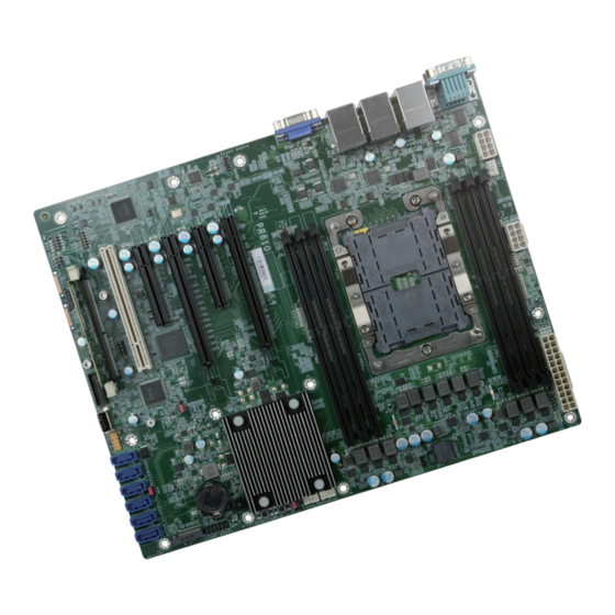
- Page 10 Chapter 2 HARDWARE INSTALLATION Chapter 2 - Hardware Installation Board Layout Note: Some components are optional and only available upon request. LAN2 DDR4_7(CPU1) COM1 USB2 3/4 DDR4_8(CPU1) Important: DDR4_9(CPU1) Electrostatic discharge (ESD) can damage your board, processor, disk drives, add-in boards, and other components.
- Page 11 Chapter 2 HARDWARE INSTALLATION System Memory Installing the DIMM Module Before installing the memory module, please make sure that the following safety cautions are well-attended. DDR4_12(CPU1) DDR4_11(CPU1) DDR4_10(CPU1) DDR4_7(CPU1) DDR4_8(CPU1) 1. Make sure the PC and all other peripheral devices connected to it has been powered DDR4_12(CPU1) DDR4_9(CPU1) down.
- Page 12 Chapter 2 HARDWARE INSTALLATION talli ng t DIMM M Removing the DIMM Module Please follow the steps below to install the memory card into the socket. Please follow the steps below to remove the memory card from the socket. Step 1: Press the eject tabs at both ends of the socket outward and downward to release them from Step 1: the locked position.
- Page 13 Chapter 2 HARDWARE INSTALLATION Installing the CPU, Fan and Heat Sink The system board is equipped with a surface mount LGA 3647 socket. This socket is exclu- sively designed for installing a LGA 3647 packaged Intel CPU. The CPU must be kept cool by using a CPU fan with heat sink. Without sufficient air circula- tion across the CPU and heat sink, the CPU will overheat damaging both the CPU and system board.
- Page 14 Chapter 2 HARDWARE INSTALLATION nstalling Chamfer corner of the 3. Place the CPU carrier on CPU and heatsink socket top of the heatsink. Place the triangular hole near the Push Pin Push Pin 5. Align the triangular mark of mounting hole #1 of the the CPU and CPU carrier to CPU Carrier with CPU heat sink.
- Page 15 Chapter 2 HARDWARE INSTALLATION Jumper Settings ME Firmware Update Clear CMOS DDR4_7(CPU1) LAN2 COM1 DDR4_7(CPU1) LAN2 COM1 DDR4_8(CPU1) USB2 3/4 DDR4_8(CPU1) USB2 3/4 DDR4_9(CPU1) DDR4_9(CPU1) Front Audio Front Audio PCIe 6 PCIe 6 DDR4_12(CPU1) PCIe 2 PCIe 1 DDR4_12(CPU1) PCIe 2 PCIe 1 (x16)
- Page 16 Chapter 2 HARDWARE INSTALLATION FLASH SECURITY OVERRIDE DDR4_7(CPU1) LAN2 COM1 DDR4_8(CPU1) USB2 3/4 DDR4_9(CPU1) Front Audio PCIe 6 DDR4_12(CPU1) PCIe 2 PCIe 1 (x16) DDR4_11(CPU1) PCIe 3 (x16) (x8) DDR4_10(CPU1) (x4) LAN1 USB2 1/2 USB3 1/2 10G_LAN 1/2 CPU1 Socket LGA3647 USB2 PCIe 3-1 USB2 7...
- Page 17 Chapter 2 HARDWARE INSTALLATION Rear I/O Ports Graphics Display LAN2 DDR4_7(CPU1) COM1 DDR4_8(CPU1) USB2 3/4 DDR4_9(CPU1) Front Audio PCIe 6 DDR4_12(CPU1) PCIe 2 PCIe 1 (x16) DDR4_11(CPU1) PCIe 3 (x16) (x8) DDR4_10(CPU1) (x4) LAN1 USB2 1/2 USB3 1/2 10G_LAN 1/2 CPU1 Socket LGA3647 USB2 PCIe 3-1...
- Page 18 Chapter 2 HARDWARE INSTALLATION COM (Serial) ports RJ45 LAN Ports DDR4_7(CPU1) LAN2 COM1 DDR4_7(CPU1) LAN2 COM1 DDR4_8(CPU1) USB2 3/4 DDR4_8(CPU1) USB2 3/4 DDR4_9(CPU1) DDR4_9(CPU1) Front Audio Front Audio PCIe 6 DDR4_12(CPU1) PCIe 6 DDR4_12(CPU1) PCIe 2 PCIe 1 PCIe 2 PCIe 1 (x16) DDR4_11(CPU1)
- Page 19 Chapter 2 HARDWARE INSTALLATION USB Ports USB 2.0 Box Headers USB 3.1 Box Headers Assignment Assignment Assignment Assignment USB 7 (USB 2.0) LAN2 DDR4_7(CPU1) COM1 V5USB4 V5USB4 V5USB5 USB2_P6_R_P USB2 3/4 DDR4_8(CPU1) DDR4_9(CPU1) Front Audio PCIe 6 DDR4_12(CPU1) USB2_HR_ USB2_HR_...
- Page 20 Chapter 2 HARDWARE INSTALLATION Internal I/O Connectors tern Front Audio SATA (Serial ATA) DDR4_7(CPU1) LAN2 COM1 DDR4_7(CPU1) LAN2 COM1 DDR4_8(CPU1) USB2 3/4 DDR4_8(CPU1) USB2 3/4 DDR4_9(CPU1) DDR4_9(CPU1) Front Audio Front Audio SATA Pin Assignment PCIe 6 PCIe 6 PCIe 2 PCIe 1 DDR4_12(CPU1)
- Page 21 Chapter 2 HARDWARE INSTALLATION tern n al tern Cooling Fan Connectors Power Connector +12V LAN2 DDR4_7(CPU1) COM1 USB2 3/4 DDR4_8(CPU1) DDR4_9(CPU1) Front Audio ATX 8-pin Power Connectors PCIe 6 PCIe 2 PCIe 1 DDR4_12(CPU1) (x16) (x16) (x8) DDR4_11(CPU1) PCIe 3 DDR4_10(CPU1)
- Page 22 Chapter 2 HARDWARE INSTALLATION tern n al tern Chassis Intrusion Front Panel LAN2 DDR4_7(CPU1) COM1 USB2 3/4 DDR4_8(CPU1) DDR4_9(CPU1) LAN2 Front Audio DDR4_7(CPU1) COM1 USB2 3/4 DDR4_8(CPU1) PCIe 6 DDR4_12(CPU1) PCIe 2 PCIe 1 DDR4_9(CPU1) (x16) DDR4_11(CPU1) PCIe 3 (x16) (x8) DDR4_10(CPU1)
- Page 23 Chapter 2 HARDWARE INSTALLATION tern n al tern nsio Expansion Slots Installing the M.2 Module LAN2 DDR4_7(CPU1) COM1 Before installing the M.2 module into the M.2 socket, please make sure that the following USB2 3/4 DDR4_8(CPU1) DDR4_9(CPU1) safety cautions are well-attended.
- Page 24 Chapter 2 HARDWARE INSTALLATION tern nsio tern n al DDR4_7(CPU1) LAN2 COM1 Please follow the steps below to install the card into the socket. DDR4_8(CPU1) USB2 3/4 DDR4_9(CPU1) Front Audio PCIe 6 PCIe 2 PCIe 1 DDR4_12(CPU1) (x16) (x16) (x8)
- Page 25 Chapter 2 HARDWARE INSTALLATION tern n al tern Battery SMBus LAN2 LAN2 DDR4_7(CPU1) COM1 DDR4_7(CPU1) COM1 USB2 3/4 USB2 3/4 DDR4_8(CPU1) DDR4_8(CPU1) DDR4_9(CPU1) DDR4_9(CPU1) Front Audio Front Audio PCIe 6 DDR4_12(CPU1) PCIe 6 DDR4_12(CPU1) PCIe 2 PCIe 1 PCIe 2 PCIe 1 (x16)
- Page 26 Chapter 2 HARDWARE INSTALLATION tern n al JTAG PLD Programming DDR4_7(CPU1) LAN2 COM1 DDR4_8(CPU1) USB2 3/4 DDR4_9(CPU1) Front Audio PCIe 6 PCIe 2 PCIe 1 DDR4_12(CPU1) JTAG PLD Connector (x16) (x16) (x8) DDR4_11(CPU1) PCIe 3 DDR4_10(CPU1) (x4) LAN1 USB2 1/2 USB3 1/2 10G_LAN 1/2...
- Page 27 Chapter 3 BIOS SETTINGS Chapter 3 - BIOS Setup Legends Overview The BIOS is a program that takes care of the basic level of communication between the CPU Keys Function and peripherals. It contains codes for various advanced features found in this system board. The BIOS allows you to configure the system and save the configuration in a battery-backed Right / Left arrow Move the highlight left or right to select a menu...
- Page 28 Chapter 3 BIOS SETTINGS Main Advanced The Main menu is the first screen that you will see when you enter the BIOS Setup Utility. The Advanced menu allows you to configure your system for basic operation. Some entries are defaults required by the system board, while others, if enabled, will improve the performance of your system or let you set some features according to your preference.
- Page 29 Chapter 3 BIOS SETTINGS a nc ACPI Configuration InsydeH2O Setup Utility Rev. 5.0 InsydeH2O Setup Utility Rev. 5.0 Advanced Advanced Support display logo with ACPI Configuration Determines the action tak ACPI Configuration ACPI BGRT table. en when the system power Wake On LAN <Disabled>...
- Page 30 Chapter 3 BIOS SETTINGS a nc a nc CPU Configuration Video Configuration Configure CPU processing related settings in this page. InsydeH2O Setup Utility Rev. 5.0 InsydeH2O Setup Utility Rev. 5.0 Advanced Advanced Set Display Mode Configure Type. Video Configuration CPU Configuration Determines the action tak en when the system power Display Mode...
- Page 31 Chapter 3 BIOS SETTINGS a nc a nc o nf SATA Configuration PCH SATA Configuration InsydeH2O Setup Utility Rev. 5.0 InsydeH2O Setup Utility Rev. 5.0 Advanced Advanced SATA Configuration PCH SATA Configuration Device. Device. PCH SATA Configuration SATA Controller(s) <Enabled> PCH sSATA Configuration SATA Speed <Auto>...
- Page 32 Chapter 3 BIOS SETTINGS a nc S AT o nf a nc PCH sSATA Configuration USB Configuration InsydeH2O Setup Utility Rev. 5.0 InsydeH2O Setup Utility Rev. 5.0 Advanced Advanced PCH sSATA Configuration USB Configuration support under UEFI environ Device. ment. SATA Controller <Enabled>...
- Page 33 Chapter 3 BIOS SETTINGS a nc PCI Express Configuration InsydeH2O Setup Utility Rev. 5.0 InsydeH2O Setup Utility Rev. 5.0 Advanced Advanced PCI Express Configuration CPU PCIE devices and CPU PCIE Configuration PCIE port configuration. settings. PCIE Configuration PCIE1 PCH PCIE Configuration PCIE2 PCIE3 (100GbE) PCIE4...
- Page 34 Chapter 3 BIOS SETTINGS a nc Debug Configuration USB Power Control InsydeH2O Setup Utility Rev. 5.0 InsydeH2O Setup Utility Rev. 5.0 Advanced Advanced Enable it to output debug mes Debug Configuration USB Power Control sage from COM port. Dynamic EFI DEBUG <On>...
- Page 35 Chapter 3 BIOS SETTINGS a nc a nc UEFI Device Manager SIO NCT6112D Configure UEFI device with option ROM, such as LAN card, etc. Configure Super I/O settings in this submenu. Scroll by moving the cursor up or down to reveal more options.
- Page 36 Chapter 3 BIOS SETTINGS a nc 1 2D Hardware Monitor This section displays the PC health status. CPU / Sytem Fan Mode = [Smart Fan] InsydeH2O Setup Utility Rev. 5.0 Advanced Boundary 0 to Boundary 3 Hardware Monitor Set the boundary temperatures that determine the fan speeds accordingly, the value ranging Voltage VBAT 3.072 V...
- Page 37 Chapter 3 BIOS SETTINGS a nc a nc 0 2Y Hardware Monitor SIO NCT7802Y This section displays the PC health status. This part is for Hardware Monitor settings. InsydeH2O Setup Utility Rev. 5.0 Advanced InsydeH2O Setup Utility Rev. 5.0 Hardware Monitor Advanced Temperature Fan Speed...
- Page 38 Chapter 3 BIOS SETTINGS a nc a nc SIO AST2500/AST2510 H2O IPMI Configuration View the super I/O settings in this submenu. InsydeH2O Setup Utility Rev. 5.0 InsydeH2O Setup Utility Rev. 5.0 Advanced Advanced Configure Serial port using op BMC UART <Enable>...
- Page 39 Chapter 3 BIOS SETTINGS a nc H 2O P MI Config BMC Configuration Configure the BMC related settings in this sub-menu. IPv4 Source InsydeH2O Setup Utility Rev. 5.0 Advanced Select how BMC IPv4 settings are configured: automatically (DHCP) or manually (Static). BMC Configuration Note: If changing to enable, BMC IPv4 IP Address...
- Page 40 Chapter 3 BIOS SETTINGS a nc H 2O P MI Config a nc H 2O P MI Config BMC Configuration User Configuration SDR List Configure the BMC's users in this sub-menu. The settings of all the 15 users are listed in the lower part of the sub-menu.
- Page 41 Chapter 3 BIOS SETTINGS a nc COM1/BMC UART Console Redirection Configure individual COM port serial settings in the submenu. Configure COM port serial settings in the submenu. InsydeH2O Setup Utility Rev. 5.0 InsydeH2O Setup Utility Rev. 5.0 Advanced Advanced E n a b l e C o n s o l e R e d i r e c t i o n Console Redirection Setup Port Enable <Enabled>...
- Page 42 Chapter 3 BIOS SETTINGS Security Boot InsydeH2O Setup Utility Rev. 5.0 InsydeH2O Setup Utility Rev. 5.0 Main Advanced Security Boot Exit Security Current TPM Device <TPM 2.0 (FTPM)> W h e n H i d d e n , d o n ’ t e x Numlock <On>...
- Page 43 Chapter 3 BIOS SETTINGS PXE Boot capability InsydeH2O Setup Utility Rev. 5.0 Boot This field is only available when "Boot Type" is set to “UEFI Boot Type” or “Dual Boot Type”, and when "Network Stack" is enabled. Select Normal Boot Option Priority or Advance Boot Normal Boot Menu <Normal>...
- Page 44 BIOS with the flash utility. For updating Insyde BIOS in UEFI mode, you may refer to the how-to video at https://www.dfi.com/tw/knowledge/video/31. InsydeH2O Setup Utility Rev. 5.0...
- Page 45 Chapter 4 RAID Chapter 4 - RAID Setup Procedure The system board allows configuring RAID on Serial ATA drives. It supports RAID 0, RAID 1, RAID 5 and RAID 10. To enable the RAID function, the following settings are required. RAID Levels 1.
- Page 46 Chapter 4 RAID roced P ro Step 3: Create a RAID Volume Step 3-1: Create a RAID Volume in UEFI Mode 1. When the Intel RST option ROM status screen displays during POST, press <Ctrl> and If the boot type is set to UEFI, RAID volume creation will be different. Please use the following ®...
- Page 47 Chapter 4 RAID roced Step 4: Install Intel Rapid Storage Technology The Intel Rapid Storage Technology can be installed from within Windows. It allows you to dis- play, manage (create, delete, migrate), and monitor SATA and RAID volume via user-friendly and icon-driven UI, and enables enhanced performance and power management for your storage subsystems.
Need help?
Do you have a question about the PR810-C622IR and is the answer not in the manual?
Questions and answers