Advertisement
Quick Links
Advertisement

Related Manuals for DFI PR810-C622


Summary of Contents for DFI PR810-C622
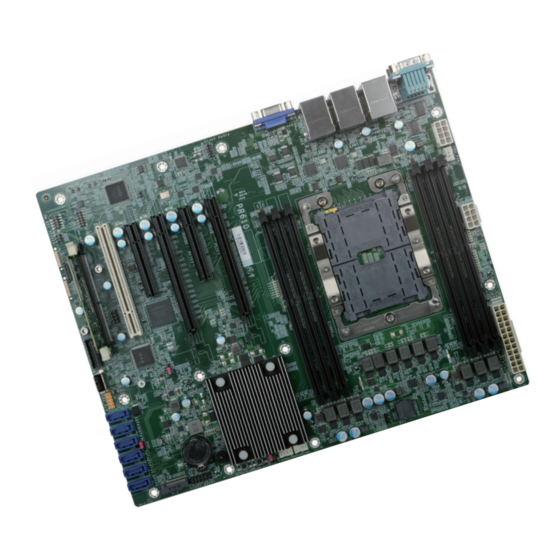
- Page 1 PR810-C622 ATX Industrial Motherboard User’s Manual A-614-M-2040...
- Page 2 1. The changes or modifications not expressly approved by the party responsible for com- pliance could void the user’s authority to operate the equipment. 2. Shielded interface cables must be used in order to comply with the emission limits. User's Manual | PR810-C622...
- Page 3 Chapter 3 - BIOS Setup.......................27 Overview ..........................27 Main............................28 Advanced ..........................28 ACPI Configuration ......................29 CPU Configuration ......................30 Video Configuration.......................30 SATA Configuration .......................31 USB Configuration ......................32 PCI Express Configuration....................33 Debug Configuration .....................34 USB Power Control ......................34 UEFI Device Manager ....................35 SIO NCT6112D.......................35 User's Manual | PR810-C622...
- Page 4 • To reduce the risk of electric shock, unplug the power cord before removing the sys- tem chassis cover for installation or servicing. After installation or servicing, cover the system chassis before plugging the power cord. User's Manual | PR810-C622...
- Page 5 When installing the system board in a new system, you will need at least the following internal The package contains the following items. If any of these items are missing or damaged, components. please contact your dealer or sales representative for assistance. • 1 x PR810-C622 motherboard • Memory module 1 x I/O shield •...
- Page 6 1 x PCIe x8 (Gen 3) 1 x PCI 1 M.2 M key2280 (PCIe Gen3 x4 NVMe/SATA) 1 x BMC Module slot for SEM2500/2510 (IPMI) 1 x 100GbE slot (x4 + x8) for EXT-100GbE proprietary module User's Manual | PR810-C622...
- Page 7 OS SUPPORT Windows 10 IoT Enterprise LTSB RS5(64-bit) Windows Server 2019 Windows Server 2016 Linux ENVIRON- Temperature Operating: 0 to 40°C MENT Storage: -40 to 85°C Humidity Operating: 5 to 90% RH Storage: 5 to 90% RH User's Manual | PR810-C622...
- Page 8 This function allows you to use a USB keyboard or USB mouse to wake up a system from the The Real Time Clock (RTC) installed on the system board allows your system to automatically S3 (STR - Suspend To RAM) state. power-on on the set date and time. User's Manual | PR810-C622...
- Page 9 PCIe Placement Port 80 SPI BIOS 128M-bit (CPU_FAN1-2) 5 * FAN Conn. (SYS_FAN1-3) SUPER IO NCT6112D UART COM1(DB9) NCT7802Y ADM213 PCIE1 PCI1 SENSORs Temp., Voltage 1 * FAN Conn. PCIE6 PCIE5 PCIE4 PCIE3 PCIE2 (SYS_FAN4) PCIE3-1 User's Manual | PR810-C622...
- Page 10 Power CPU FAN2 CPU FAN2 Status LEDs M.2-M M.2-M CPU0 Socket LGA3647 CPU0 Socket LGA3647 Front SYS-FAN ATX Power DDR4_1(CPU0) Panel DDR4_2(CPU0) DDR4_3(CPU0) Reset Button Power Button ATX Power Front SYS-FAN DDR4_1(CPU0) Panel DDR4_2(CPU0) DDR4 3(CPU0) User's Manual | PR810-C622...
- Page 11 DIMMs. Not all slots need to be populated. Socket Side View Features • 12 x 288-pin RDIMM up to 384GB • Single Channel DDR4 up to 2133/2400/2666/2933 MHZ • (Support Intel DC Persistent Memory) User's Manual | PR810-C622...
- Page 12 Hold the card by its edges and remove it from the slot. The tabs snap automatically to the edges of the card and lock the card in place. Step 1 Step 1 Step 2 Step 2 Step 3 Step 3 User's Manual | PR810-C622...
- Page 13 CPU fan and heat sink assembly. If ® your CPU was purchased separately, make sure to only use Intel®-certified fan and heat sink. Latch Triangular mark Gold triangular mark Latch CPU Carrier (bottom view) User's Manual | PR810-C622...
- Page 14 (top view) Triangular hole 6. Connect the CPU fan’s CPU Fan power cable to the CPU fan connector on the system board. 4. Slide the protective caps open and detach them from the board. User's Manual | PR810-C622...
- Page 15 1 and pin 2. 3. Plug the power cord and power-on the system. 1-2 On: Normal (default) 2-3 On: Force ME Update 1-2 On: Normal (default) 2-3 On: Clear CMOS User's Manual | PR810-C622...
- Page 16 JP16 JP15 +12V Power CPU FAN2 M.2-M CPU0 Socket LGA3647 Front SYS-FAN ATX Power DDR4_1(CPU0) Panel DDR4_2(CPU0) DDR4 3(CPU0) JP8 is the switch of FLASH SECURITY OVERRIDE. 1-2 On: Disable (default) 2-3 On: Enable User's Manual | PR810-C622...
- Page 17 VGA port. After you plug the monitor’s cable connector into the VGA port, gen- tly tighten the cable screws to hold the connector in place. BIOS Setting Configure the display devices in the "Advanced" menu (“Video Configuration” submenu) of the BIOS. User's Manual | PR810-C622...
- Page 18 NCT6112D" submenus) of the BIOS. Features • 2 x Intel I210AT PCIe (10/100/1000Mbps) ® • 2 x Intel x557-AT2 (10GbE) ® Note: The BMC COM port is used to monitor the IPMI functions and the BMC on the SEM2500/SEM2510 card. User's Manual | PR810-C622...
- Page 19 If you are using the Wake-On-USB Keyboard/Mouse function for 2 USB ports, the +5V_standby power source of your power supply must support ≥1.5A. For 3 or more USB ports, the +5V_standby power source of your power supply must support ≥2A. User's Manual | PR810-C622...
- Page 20 N.C. • Serial ATA 3.0 ports are with data transfer rate up to 6Gb/s Line2-R Mic2-JD • Integrated Advanced Host Controller Interface (AHCI) controller • Support RAID 0, RAID 1, RAID 5, RAID 10 Line2-L Line2-JD User's Manual | PR810-C622...
- Page 21 Insufficient power supplied to the system may result in instability or malfunction Speed Control of the add-in boards and peripherals. Calculating the system’s approximate power usage is important to ensure that the power supply meets the system’s consump- tion requirements. User's Manual | PR810-C622...
- Page 22 Power On Suspend) state, it will blink at 1-second intervals. When the system is in the S3 (STR - Suspend To RAM) state, it will blink at 4-second intervals. Power Button This button is used to switch the system's power on or off . User's Manual | PR810-C622...
- Page 23 This DDR4 SO-DIMM socket is to support SEM2500/ 45mm SEM2510 module for additional IPMI management, BMC, and VGA output. 69.6mm BIOS Setting Configure PCIe root ports in the "Advanced > PCI Express Configuration” submenu of the BIOS. User's Manual | PR810-C622...
- Page 24 LAD1 the gap between the card and the stand-off closes up. The RST# LAD0 card should be lying parallel to the board when it’s correctly FRAME# 3.3V mounted. LAD3 LAD2 SERIRQ N.C. User's Manual | PR810-C622...
- Page 25 • There exists explosion hazard if the battery is incorrectly installed. Pin Assignment Pin Assignment • Replace only with the same or equivalent type recommended by the manufacturer. 3V3_AUX • Dispose of used batteries according to local ordinances. SMB_HOST_STBY_ SMB_HOST_STBY_ LVC3_SCL LVC3_SDA PU_PCH_TLS_ ENABLE_STRAP User's Manual | PR810-C622...
- Page 26 DDR4_2(CPU0) DDR4_3(CPU0) The JTAG PLD connector is used to verify and test printed circuits. JTAG PLD Pin Assignment Assignment Assignment 3V3SB Test Data Out Test Data In EN N Reset Test Mode Select Test Clock User's Manual | PR810-C622...
- Page 27 When “ ” appears on the left of a particular field, it indicates that a submenu which contains additional options are available for that field. To display the submenu, move the highlight to that field and press <Enter>. User's Manual | PR810-C622...
- Page 28 00 to 59. Second displays seconds from 00 to 59. System Date The date format is <month>, <date>, <year>. Month displays the month, from 01 to 12. Date displays the date, from 01 to 31. Year displays the year, from 2000 to 2099. User's Manual | PR810-C622...
- Page 29 Real-time clock (RTC) battery. [Wake up time] Configure the time of day the system will wake on RTC — [HH:MM:SS]. This field will only ap- pear when “Wake On RTC” is enabled. User's Manual | PR810-C622...
- Page 30 Please make sure that the OS operating on your system is optimized for Hyper-Threading, e.g. Windows and Linux. This field is not available when the equipped CPU does not support Hyper- threading. User's Manual | PR810-C622...
- Page 31 AHCI This option allows the Serial ATA controller(s) to use AHCI (Advanced Host Control- ler Interface). RAID This option allows the Serial ATA controller(s) to use UEFI, RAID, and Intel Rapid Storage Technology. SATA Port 0-5/Hot Plug Enable or disable each Serial ATA port and its hot plug function. User's Manual | PR810-C622...
- Page 32 Select Serial ATA controller(s) speed — Auto, Gen1 (1.5 Gbit/s), Gen2 (3 Gbit/s) or Gen 3 (6 Enable or disable XHCI Hand-off. Gbit/s). SATA Port / Hot Plug Enable or disable each Serial ATA port and its hot plug function. User's Manual | PR810-C622...
- Page 33 Change Values Setup Defaults Hot Plug Exit Select Item Enter Select SubMenu Save and Exit Enable or disable hot plug function of the port. This field may not appear when the port does not support hot plug. User's Manual | PR810-C622...
- Page 34 Enter the numeric value for EFI debug print level. The default is 0x8000004F. EFI debug serial port Enter the serial port to output EFI debug message. The default is 0x3F8. EFI debug baud rate Enter the baud rate to output EFI debug message. The default is 115200. User's Manual | PR810-C622...
- Page 35 Network Device will not be configurable in Device Manager if "Network Stack" is Set the timeout value of the WDT — 1-255 seconds. disabled in the "Boot" menu. Case Open Alert Enable or disable case open alert. Clean Case Open Status Clean current case open status including alert. User's Manual | PR810-C622...
- Page 36 Enable or disable the system smart fan. When disabled, fan speed will not be controllable ac- cording to different system temperatures. Instead, a Fix Fan Speed Count field will be displayed to configure at which speed the fan will always be fixed regardless of system temperature. User's Manual | PR810-C622...
- Page 37 Enable or disable the system smart fan. When disabled, fan speed will not be controllable ac- cording to different system temperatures. Instead, a Fix Fan Speed Count field will be displayed to configure at which speed the fan will always be fixed regardless of system temperature. User's Manual | PR810-C622...
- Page 38 Enable or disable this field for IPMI driver installation. SIO AST2500/AST2510 is only present when the board supports the IPMI func- Boot Option Support tions and equipped with SEM2500/SEM2510. Enable or disable IPMI boot option function. User's Manual | PR810-C622...
- Page 39 BMC's LAN channel number. There are three channels available — channel number from 1 to 3. To configure a LAN channel, insert a channel number, and the IP settings of the selected chan- nel will be listed in the following. User's Manual | PR810-C622...
- Page 40 Select among Reserved, Callback, User, Operator, Administrator, and No Access. The privilege of a user ID can be set differently in different channels. Add current setting to list Save the setting of the current user ID's previlege of the current channel. User's Manual | PR810-C622...
- Page 41 Select data bits — 7 bits or 8 bits. Parity Select parity bits — none, even or odd. Stop Bits Select stop bits — 1 bit or 2 bits. Flow Control Select flow control type — none, RTS/CTS or XON/XOFF. User's Manual | PR810-C622...
- Page 42 This field is used to enable or disable network stacks, i.e. IPv4 or IPv6 network protocols. Note: The devices shown here are based on a carrier board that may not resemble your actual carrier board. The actual I/O devices depend entirely on those present on your actual carrier board. User's Manual | PR810-C622...
- Page 43 "PXE Boot to LAN", "PXE boot capability", "Network Stack" and the LAN controller of the said LAN (go to "Advanced" > "PCI Express Configuration") are enabled. Please press F10 to save the settings and re-start the system board for the settings to take effect. User's Manual | PR810-C622...
- Page 44 Select YES and press <Enter> to load optimal defaults. Discard Changes Select YES and press <Enter> to exit the system setup without saving your changes. Save Setting to file Select this option to save BIOS configuration settings to a USB flash device. User's Manual | PR810-C622...
- Page 45 Single Drive Failure Disk mirroring Block-level data striping with RAID 5 Single Drive Failure distributed parity 1 Disk Per Mirrored Combination of RAID 0 (data striping) RAID 10 Stripe (not same mirror) and RAID 1 (mirroring) User's Manual | PR810-C622...
- Page 46 5. Press <Enter>. 6. Use the up or down arrow keys to select the strip size and press <Enter>. 7. Enter the volume size and press <Enter>. 8. At the prompt, press <Y> to confirm volume creation. User's Manual | PR810-C622...
- Page 47 The Intel Rapid Storage Technology can be installed from within Windows. It allows you to dis- play, manage (create, delete, migrate), and monitor SATA and RAID volume via user-friendly and icon-driven UI, and enables enhanced performance and power management for your storage subsystems. User's Manual | PR810-C622 ver.021_EVT_11-2520_16-12...
Need help?
Do you have a question about the PR810-C622 and is the answer not in the manual?
Questions and answers