
Related Manuals for DFI PR611-C621DR


Summary of Contents for DFI PR611-C621DR
- Page 1 PR611-C621 ATX Industrial Motherboard User’s Manual ver.A_MP_3-1621_12-9 A-583-M-2007...
- Page 2 Copyright FCC and DOC Statement on Class B This publication contains information that is protected by copyright. No part of it may be repro- This equipment has been tested and found to comply with the limits for a Class B digital duced in any form or by any means or used to make any transformation/adaptation without the device, pursuant to Part 15 of the FCC rules.
-
Page 3: Table Of Contents
Table of Contents Boot ............................42 Exit ............................44 Updating the BIOS ........................44 Chapter 1 - Introduction........................ 6 Notice: BIOS SPI ROM......................44 Specifications ......................... 6 Chapter 4 - RAID ..........................45 Features ..........................8 RAID Levels ...........................45 Chapter 2 - Hardware Installation ....................8 Setup Procedure ........................45 Board Layout........................... - Page 4 About this Manual Static Electricity Precautions This manual can be downloaded from the website. The manual is subject to change and up- It is quite easy to inadvertently damage your PC, system board, components or devices even date without notice, and may be based on editions that do not resemble your actual products. before installing them in your system unit.
- Page 5 About the Package The package contains the following items. If any of these items are missing or damaged, please contact your dealer or sales representative for assistance. 1 PR611-C621 motherboard 1 I/O shield A49-PR6110-020G 2 M.2 screw A32-112016-041G 1 CPU Clip 348-436471-100G The board and accessories in the package may not come similar to the information listed above.
- Page 6 Chapter 1 INTRODUCTION Chapter 1 - Introduction 2nd Generation Intel® Xeon® Scalable Processor Family, LGA 3647 Socket: Intel® Xeon® Gold 6252N (24 Cores, 35.75M Cache, up to 3.6 X Specifications GHz); 150W Intel® Xeon® Gold 6238T (22 Cores, 30.25M Cache, up to 3.7 GHz);...
- Page 7 Chapter 1 INTRODUCTION Rear I/O Ethernet 2 x GbE (RJ-45) Country of Country of Taiwan 1 x dedicated IPMI LAN (opt.) Origin Origin Serial 1 x RS-232 (DB-9) 4x USB 3.1 Gen1 2x USB 2.0 stack (opt.w/ RJ45+USB2.0 stack) Internal I/O 2x USB 2.0 header (2x USB 2.0) 1x USB 2.0 vertical Type A 1x USB 3.1 Gen1 header (2x USB 3.1 Gen1)
-
Page 8: Features
Chapter 1 INTRODUCTION X Features Watchdog Timer PCI Express The Watchdog Timer function allows your application to regularly “clear” the system at the set PCI Express is a high bandwidth I/O infrastructure that possesses the ability to scale speeds time interval. If the system hangs or fails to function, it will reset at the set time interval so that by forming multiple lanes. -
Page 9: Chapter 2 - Hardware Installation
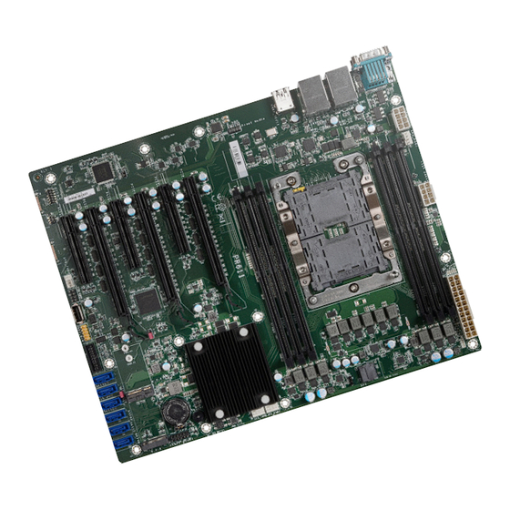
Chapter 2 HARDWARE INSTALLATION Chapter 2 - Hardware Installation X Board Layout Note: Some components are optional and only available upon request. +12V Power +12V Power CPU FAN +12V Power DDR4_3 COM1 Note Important: DDR4_2 Electrostatic discharge (ESD) can damage your board, processor, disk drives, DDR4_1 add-in boards, and other components. -
Page 10: System Memory
Chapter 2 HARDWARE INSTALLATION X System Memory System Memory Installing the DIMM Module Before installing the memory module, please make sure that the following safety cautions are DDR4_3 well-attended. DDR4_2 DDR4_1 1. Make sure the PC and all other peripheral devices connected to it has been powered down. -
Page 11: Removing The Dimm Module
Chapter 2 HARDWARE INSTALLATION System Memory Installing the DIMM Module System Memory Removing the DIMM Module Please follow the steps below to install the memory card into the socket. Please follow the steps below to remove the memory card from the socket. Step 1: Press the eject tabs at both ends of the socket outward and downward to release them from DDR4 DIMM... -
Page 12: Cpu
Chapter 2 HARDWARE INSTALLATION X CPU Installing the CPU, Fan and Heat Sink The system board is equipped with a surface mount LGA 3647 socket. This socket is exclu- sively designed for installing a LGA 3647 packaged Intel CPU. The CPU must be kept cool by using a CPU fan with heat sink. Without sufficient air circula- tion across the CPU and heat sink, the CPU will overheat damaging both the CPU and system board. - Page 13 Chapter 2 HARDWARE INSTALLATION Installing the CPU Chamfer corner of the 3. Place the CPU carrier on CPU and heatsink socket top of the heatsink. Place the triangular hole near the Push Pin Push Pin 5. Align the triangular mark of mounting hole #1 of the the CPU and CPU carrier to CPU Carrier with CPU...
-
Page 14: Jumper Settings
Chapter 2 HARDWARE INSTALLATION X Jumper Settings ME Firmware Update Clear CMOS JP15 JP16 If any anomaly of the followings is encountered — a) CMOS data is corrupted; b) you forgot the supervisor or user password; JP16 is used for updating the ME firmware. c) failure to start the system due to BIOS mis-configuration —... -
Page 15: Rear I/O Ports
Chapter 2 HARDWARE INSTALLATION X Rear I/O Ports Graphics Display Optional VGA (DB15) I/O Connectors „ Rear I/O Connectors VGA (optional) COM 1 A VGA display port of DB15 connector is available when the motherboard is with IPMI func- tions and BMC. VGA Port LAN 1 LAN 2... -
Page 16: Com (Serial) Ports
Chapter 2 HARDWARE INSTALLATION Rear I/O Ports Rear I/O Ports COM (Serial) ports RJ45 LAN Ports LAN 1 LAN 2 COM 1 (DB9) „ BMC COM port (COM 2) IPMI LAN (optional) The serial ports are asynchronous communi- „ COM Port Pin Assignment The LAN ports allow the system board to connect to a local area network (LAN) by means of a cation ports with 16C550A-compatible UARTs RS232... -
Page 17: Usb Ports
Chapter 2 HARDWARE INSTALLATION Rear I/O Ports USB Ports „ USB 2.0 Box Headers „ USB 3.1 Box Headers Assignment Assignment Assignment Assignment SSRX1- USB 2 (USB 3.1 Gen 1) USB 4 (USB 3.1 Gen 1) SSRX1+ USB 1 (USB 3.1 Gen 1) USB 3 (USB 3.1 Gen 1) SSTX2+ N.C. -
Page 18: Internal I/O Connectors
Chapter 2 HARDWARE INSTALLATION X Internal I/O Connectors Internal I/O Connectors Front Audio SATA (Serial ATA) „ SATA Pin Assignment „ Front Audio SATA 5/4/3/2/1/0 from left to right The Serial ATA (SATA) connectors are used to connect the Serial ATA device. SATA 3.0 is sup- The Front Audio internal connector allows you to connect to audio jacks at the front panel of ported by the five SATA ports and provides data rate up to 6Gb/s. -
Page 19: Cooling Fan Connectors
Chapter 2 HARDWARE INSTALLATION Internal I/O Connectors Internal I/O Connectors Cooling Fan Connectors Power Connector +12V CPU Fan (PWM) „ ATX 8-pin Power Connectors +12V „ PWM Fan System Fan 1 (PWM) System Fan 2 (PWM) „ ATX 24-pin Power System Fan 3 (PWM) Connector These fan connectors are used to connect cooling fans. -
Page 20: Chassis Intrusion
Chapter 2 HARDWARE INSTALLATION Internal I/O Connectors Internal I/O Connectors Chassis Intrusion Front Panel „ Front Panel Connector RESET ATX-SW „ Chassis Intrusion HD-LED PWR-LED „ Front Panel Pin Assignment Assignment Assignment N.C. LED Power HDD Power PWR-LED LED Power The board supports the chassis intrusion detection function. -
Page 21: Expansion Slots
Chapter 2 HARDWARE INSTALLATION Internal I/O Connectors Internal I/O Connectors Expansion Slots Expansion Slots Installing the M.2 Module Before installing the M.2 module into the M.2 socket, please make sure that the following safety cautions are well-attended. 1. Make sure the PC and all other peripheral devices connected to it has been powered PCIe 1 (PCIe x16;... -
Page 22: Lpc
Chapter 2 HARDWARE INSTALLATION Internal I/O Connectors Expansion Slots Internal I/O Connectors Please follow the steps below to install the card into the socket. Step 1: „ LPC Connector Insert the card into the socket at an angle while making sure the notch and key are perfectly aligned. -
Page 23: Battery
Chapter 2 HARDWARE INSTALLATION Internal I/O Connectors Internal I/O Connectors Battery SMBus „ SMBus „ Battery Holder The lithium ion battery addendum supplies power to the real-time clock and CMOS memory The SMBus (System Management Bus) connector is used to connect the SMBus device. It is a as an auxiliary source of power when the main power is shut off. -
Page 24: Jtag Pld Programming
Chapter 2 HARDWARE INSTALLATION Internal I/O Connectors JTAG PLD Programming „ JTAG PLD Connector The JTAG PLD connector is used to verify and test printed circuits. „ JTAG PLD Pin Assignment Assignment Assignment 3V3SB Test Data Out Test Data In EN N Reset Test Mode Select... -
Page 25: Chapter 3 - Bios Settings
Chapter 3 BIOS SETTINGS Chapter 3 - BIOS Settings Legends X Overview The BIOS is a program that takes care of the basic level of communication between the CPU Keys Function and peripherals. It contains codes for various advanced features found in this system board. The BIOS allows you to configure the system and save the configuration in a battery-backed Right / Left arrow Move the highlight left or right to select a menu... -
Page 26: Main
Chapter 3 BIOS SETTINGS X Main X Advanced The Main menu is the first screen that you will see when you enter the BIOS Setup Utility. The Advanced menu allows you to configure your system for basic operation. Some entries are defaults required by the system board, while others, if enabled, will improve the performance of your system or let you set some features according to your preference. -
Page 27: Cpu Configuration
Chapter 3 BIOS SETTINGS Advanced Advanced RC ACPI Configuration CPU Configuration InsydeH2O Setup Utility Rev. 5.0 InsydeH2O Setup Utility Rev. 5.0 Advanced Advanced CPU Configuration Determines the action tak- ACPI Configuration Determines the action tak- en when the system power en when the system power Intel Speed Step <Enabled>... -
Page 28: Video Configuration
Chapter 3 BIOS SETTINGS Advanced Advanced Video Configuration SATA Configuration Enable/Disable SATA Device. InsydeH2O Setup Utility Rev. 5.0 InsydeH2O Setup Utility Rev. 5.0 Advanced Advanced Video Configuration SATA Configuration Display Mode <On Board First> ►PCH SATA Configuration PCIE 64-bits MMIO decode <Enabled>... - Page 29 Chapter 3 BIOS SETTINGS Advanced SATA Configuration Advanced SATA Configuration ►PCH SATA Configuration ►PCH sSATA Configuration InsydeH2O Setup Utility Rev. 5.0 InsydeH2O Setup Utility Rev. 5.0 Advanced Advanced PCH SATA Configuration Enable/Disable SATA PCH sSATA Configuration Enable/Disable SATA Device. Device. SATA Controller(s) <Enabled>...
-
Page 30: Usb Configuration
Chapter 3 BIOS SETTINGS Advanced Advanced USB Configuration PCI Express Configuration InsydeH2O Setup Utility Rev. 5.0 InsydeH2O Setup Utility Rev. 5.0 Advanced Advanced USB Configuration PCI Express Configuration Enable/Disable SATA Device. Legacy USB Support <Enabled> ►CPU PCIE Configuration XHCI Hand-off <Disabled>... -
Page 31: Debug Configuration
Chapter 3 BIOS SETTINGS Advanced Advanced Debug Configuration UEFI Device Manager This section configures Debug setting. Configure UEFI device with option ROM, such as LAN card, etc. InsydeH2O Setup Utility Rev. 5.0 InsydeH2O Setup Utility Rev. 5.0 Advanced Advanced Enable it to output debug mes- UEFI Device Manager Setting Debug Configuration UEFI Device Manager... -
Page 32: Usb Power Control
Chapter 3 BIOS SETTINGS Advanced Advanced USB Power Control SIO NCT6112D Configure USB power output between 5V and 5V_Dual. Configure Super I/O settings in this submenu. Scroll by moving the cursor up or down to reveal more options. InsydeH2O Setup Utility Rev. - Page 33 Chapter 3 BIOS SETTINGS Advanced SIO NCT6112D X Hardware Monitor This section displays the PC health status. ▼ CPU / Sytem Fan Mode = [Smart Fan] InsydeH2O Setup Utility Rev. 5.0 Advanced Boundary 0 to Boundary 3 Hardware Monitor Set the boundary temperatures that determine the fan speeds accordingly, the value ranging Voltage VBAT 3.072 V...
-
Page 34: Sio Ast2500/Ast2510
Chapter 3 BIOS SETTINGS Advanced Advanced SIO AST2500/AST2510 H2O IPMI Configuration View the super I/O settings in this submenu. InsydeH2O Setup Utility Rev. 5.0 InsydeH2O Setup Utility Rev. 5.0 E n a b l e / D i s a b l e I P M I S u p p o r t . Advanced Advanced Note: If changing to enable, BMC... - Page 35 Chapter 3 BIOS SETTINGS Advanced H2O IPMI Configuration X BMC Configuration Configure the BMC related settings in this sub-menu. IPv4 Source InsydeH2O Setup Utility Rev. 5.0 Advanced Select how BMC IPv4 settings are configured: automatically (DHCP) or manually (Static). E n a b l e / D i s a b l e I P M I S u p p o r t . BMC Configuration Note: If changing to enable, BMC IPv4 IP Address...
- Page 36 Chapter 3 BIOS SETTINGS Advanced H2O IPMI Configuration Advanced H2O IPMI Configuration X BMC Configuration X User Configuration X SDR List Configure the BMC's users in this sub-menu. The settings of all the 15 users are listed in the lower part of the sub-menu. InsydeH2O Setup Utility Rev.
-
Page 37: Console Redirection
Chapter 3 BIOS SETTINGS Advanced X COM1/COM2/BMC UART Console Redirection Configure individual COM port serial settings in the submenu. Configure COM port serial settings in the submenu. InsydeH2O Setup Utility Rev. 5.0 InsydeH2O Setup Utility Rev. 5.0 Advanced Advanced E n a b l e C o n s o l e R e d i r e c t i o n Console Redirection Setup Port Enable <Enabled>... -
Page 38: Security
Chapter 3 BIOS SETTINGS X Security X Boot InsydeH2O Setup Utility Rev. 5.0 InsydeH2O Setup Utility Rev. 5.0 Main Advanced Security Boot Exit Security Current TPM Device <TPM 2.0 (FTPM)> W h e n H i d d e n , d o n ’ t e x - Numlock <On>... - Page 39 Chapter 3 BIOS SETTINGS Boot PXE Boot capability InsydeH2O Setup Utility Rev. 5.0 Boot This field is only available when "Boot Type" is set to “UEFI Boot Type” or “Dual Boot Type”, and when "Network Stack" is enabled. EFI/Legacy Select Normal Boot Option Priority or Advance Boot Normal Boot Menu <Normal>...
- Page 40 BIOS with the flash utility. For updating Insyde BIOS in UEFI mode, you may refer to the how-to video at https://www.dfi.com/tw/knowledge/video/31. InsydeH2O Setup Utility Rev. 5.0...
- Page 41 Chapter 5 RAID Chapter 4 - RAID X Setup Procedure The system board allows configuring RAID on Serial ATA drives. It supports RAID 0, RAID 1, RAID 5 and RAID 10. To enable the RAID function, the following settings are required. X RAID Levels 1.
- Page 42 Chapter 5 RAID Setup Procedure Setup Procedure Step 3: Create a RAID Volume Step 3-1: Create a RAID Volume in UEFI Mode 1. When the Intel RST option ROM status screen displays during POST, press <Ctrl> and If the boot type is set to UEFI, RAID volume creation will be different. Please use the following ®...
- Page 43 Chapter 5 RAID Setup Procedure Step 4: Install Intel Rapid Storage Technology The Intel Rapid Storage Technology can be installed from within Windows. It allows you to dis- play, manage (create, delete, migrate), and monitor SATA and RAID volume via user-friendly and icon-driven UI, and enables enhanced performance and power management for your storage subsystems.
Need help?
Do you have a question about the PR611-C621DR and is the answer not in the manual?
Questions and answers