
Subscribe to Our Youtube Channel
Related Manuals for Teldat M20


Summary of Contents for Teldat M20
- Page 1 Manual Windbit M20 Edge Router Installation Manual Copyright© Windbit-dm1095-I Version 1.0 11/2024 Teldat S.A. M20 Edge Router...
- Page 2 This publication is subject to change. Teldat S.A. offers no warranty whatsoever for information contained in this manual. Teldat S.A. is not liable for any direct, indirect, collateral, consequential or any other damage connected to the deliv- ery, supply or use of this manual.
-
Page 3: Table Of Contents
M20 ........ - Page 4 Dimensions and weight ....... . A.5.8 Environmental specifications ......M20 Edge Router...
-
Page 5: I Related Documents
Related Documents Windbit I Related Documents OSDx Documentation available at https://support.teldat.com/osdx-doc M20 Edge Router... -
Page 6: About This Guide
1 About this Guide Windbit Chapter 1 About this Guide This installation guide for the M20 router contains information on how to correctly install this device in a working en- vironment. 1.1 Supported devices The information provided in this installation guide only applies to the M20 router. -
Page 7: M20
2.2.2 Hardware monitoring The LEDs on the front panel are used to monitor the hardware in the M20 router. These LEDs provide visual informa- tion on the state of the device and reference the condition of the hardware components, indicating whether there is connectivity, data flow, etc. -
Page 8: Components And Power Supply
3 Components and Power Supply Windbit Chapter 3 Components and Power Supply The following chapter provides detailed information on the chassis of the M20 router and its components. This in- formation includes: • Components • Information on installation • Power supply •... - Page 9 On: Power Input OK. System Off: System error. On: System initialized and operating. In addition to the LEDs described in the above table, the front panel also has LEDs linked to the Combos RJ45 and RJ45 Ethernet interfaces. M20 Edge Router...
-
Page 10: Rear Panel
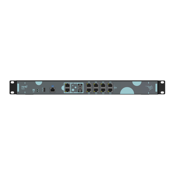
Rear panel components Item Description Bonding screw for protective earth. Refer to Ground the router on page 9 for more information. Power socket. Refer to Power source on page 9 for more information on Power Connection and M20 Edge Router... -
Page 11: Installation
3.2.1 Standalone M20 devices can be placed as standalone devices on a flat, stable surface. The adhesive rubber feet must be stuck to the underside panel to prevent the router from sliding. Make sure there is enough space around the router (for ventilation purposes) and check that the power cord and data cables can easily reach it. - Page 12 • Step 2. Use the screws and cage nuts provided with the router to secure the router in the rack. Warning Installing the router in a rack requires two people. One person should position the router in the rack, while the other secures it using the rack screws. Fig. 8: Rack installation M20 Edge Router...
-
Page 13: Power Source
Windbit 3.2.3.1 Ground the router Ensure the rack on which the M20 is to be mounted is properly grounded in com- pliance with ETSI ETS 300 253. Verify that there is a good electrical connection to the grounding point on the rack (no paint or isolation surface treatment). -
Page 14: Rst Button
Note Some devices leave the factory with customized settings. This personalization means your router's de- fault configuration may be different from the one shown above. 3.5 Connecting the data The M20 router has the following data connections. M20 Edge Router... -
Page 15: 8-Port Ethernet Switch Connections (Eth0)
During booting and in BIOS mode, only the port 0 is available. 3.5.2 Ethernet Combo connections (ETH1 to ETH2) Two Combo ports, Copper (RJ45) and Fiber ports (SFP), are available on the M20, labeled as ETH1 to ETH2 for in- dividual/dedicated LAN connections. -
Page 16: Connecting For Configuration
70ºC (160°F) and be too hot to touch with bare hands. 3.5.3 Connecting for configuration The M20 has a RJ45 female connector on the front panel (labeled "Conf") that provides access to the device's local console. -
Page 17: Compliance
Verletzungen oder zum Tod führen kann, wenn sie nicht ver- mieden wird. ADVERTENCIA: Palabra de advertencia utilizada para indicar una situación po- tencialmente peligrosa que, si no se evita, podría provocar la muerte o lesiones graves. M20 Edge Router... -
Page 18: Safety Warnings
4 Compliance Windbit 4.3 Safety warnings M20 Edge Router... - Page 19 4 Compliance Windbit M20 Edge Router...
-
Page 20: Weee Information
Authorization is published by ECHA and periodically updated. The manufacturer ac- counts for substances found in a concentration over 0.1% in weight. A declaration is provided to customers upon re- quest. M20 Edge Router... -
Page 21: Ec Declaration Of Conformity
Richtlinie 2014/30/EU (EMC) Richtlinie 2014/35/EU (LVD) Richtlinien 2011/65/EU und 2015/863/EU (RoHS) des Europäischen Parlaments. Spanish (ES) Español Por la presente, Teldat S.A. declara que el tipo de equipo radioeléctrico M20 es conforme con: Directiva 2014/30/UE (EMC) Directiva 2014/35/UE (LVD) Directiva 2011/65/UE (RoHS) del Parlamento Europeo y del Consejo. -
Page 22: Appendix A Technical Information
A.2 Connecting to the device A.2.1 Connecting using the local console (Conf connector) The M20 router has a RJ45 female connector on the front panel, known as "Conf", that provides access to the device's local console. Conf Connector Fig. -
Page 23: Updating The Software
(https://support.teldat.com/osdx-doc), System Administration, Upgrade section. Example: Log into the M20 CLI via the local console, or using SSH or Telnet on any interface if either of these services are en- abled. You will need a user (admin) and a password (admin) Issue the command image add <imagefile>... -
Page 24: Ethernet Sfp Connector
A.4.3 USB 3.0 connector Type-A Signal VBUS D- (USB 2.0) D+ (USB 2.0) SSRX- (USB 3.0) SSRX+ (USB3.0) GND_DRAIN SSTX- (USB 3.0) SSTX+ (USB 3.0) Shell Shield A.4.4 Configuration connector RJ45 CONFIGURATION RJ45 PIN CONF A.5 Technical specifications M20 Edge Router... -
Page 25: Hardware Architecture
2-port (Combo, SFP port) (ETH1, ETH2) CONNECTOR Standard SFP connector. A.5.4 USB interface TERMINAL One USB 3.0 (Super Speed). CONNECTOR Type-A. A.5.5 Configuration interface LOCAL TERMINAL RS-232 115200-8-N-1 without flow control. CONNECTOR RJ45 female on the device’s front panel. M20 Edge Router... -
Page 26: Power Supply
LENGTH x WIDTH x HEIGHT 430 x 444 x 44 mm 430 x 483 x 44 mm (with backets) WEIGHT 4,0 kg. A.5.8 Environmental specifications TEMPERATURE OPERATING NORMALLY: 0 ºC to 40 ºC RELATIVE HUMIDITY On: 5 % to 90 % M20 Edge Router...
Need help?
Do you have a question about the M20 and is the answer not in the manual?
Questions and answers