
Related Manuals for NSD ABSOCODER NCW-3DNIPMP


Summary of Contents for NSD ABSOCODER NCW-3DNIPMP
- Page 1 ZEF005850106 ABSOCODER Converter NCW-3DNIPMP Specifications & Instruction Manual Applicable sensor: MRE-32SP062 MRE-G[ ]SP062...
-
Page 3: Table Of Contents
CONTENTS INTRODUCTION ..............................i COPYRIGHT................................ i GENERAL SAFETY RULES ..........................ii REVISION HISTORY ............................iii 1. OVERVIEW ..............................1 1-1. Features ........................................2 2. MODEL SELECTION WHEN ORDERING ....................3 3. SPECIFICATIONS ............................4 3-1. Converter Specifications ..................................4 3-2. ABSOCODER Sensor Specification ..............................6 3-3. - Page 4 9-6-3. Creation of a controller project ..............................45 9-6-4. Adding NCW-3DNIP to the controller project ........................... 47 9-6-5. Download the project .................................. 54 9-7. Set Parameter of NCW-3DHIP ................................. 58 9-7-1. Parameter List ..................................... 59 9-7-2. Parameters Setting Procedure ..............................60 9-8.
- Page 5 APPENDIX 3. WEB SERVER FUNCTION ....................126 APPENDIX 3-1. Login Procedures ................................ 127 APPENDIX 3-2. User management function ............................128 APPENDIX 3-3. Setting / Reference display ............................129...
-
Page 6: Introduction
INTRODUCTION Thank you very much for purchasing our product. Before operating this product, be sure to carefully read this manual so that you may fully understand the product, safety instructions and precautions. - Please submit this manual to the operators actually involved in operation. - Please keep this manual in a handy place. -
Page 7: General Safety Rules
- Be sure to store the converter in designed temperature and humidity 8. Disposal range, and do not expose to direct sunlight. - Be sure to consult with NSD when the converter is stored for long CAUTION periods. - Be sure to handle the converter and ABSOCODER sensor as... -
Page 8: Revision History
REVISION HISTORY The Document No. appears at the upper right of this manual's cover page. Document No. Date Revision Description ZEF005850100 8, Dec., 2016 1st Edition Japanese document: ZEF005850000 ZEF005850101 15, May, 2017 2nd Edition Japanese document: ZEF005850001 ZEF005850102 14, Dec., 2018 3rd Edition Japanese document: ZEF005850002 ZEF005850103 7, Nov., 2019... - Page 9 - MEMO -...
-
Page 10: Overview
Automation, Inc. are connected by the network. Therefore, we explain the manual by using the following software. ①BOOTP/DHCP Server ②RSLinx Classic ③RSLogix5000 ④RSNetWorx For details of software instruction, refer to each product manual. If the configuration tool is needed the definition file (EDS file), download it from NSD website. -
Page 11: Features
1-1. Features (1) High reliability An absolute position detection format ensures accurate position detection even if a power interruption or unexpected noise condition occurs. An origin returning operation is not required. (2) Superior durability ABSOCODER sensor is not used electronic parts except coils and resistance, and it features a no-contact construction excepting bearing. -
Page 12: Model Selection When Ordering
(If a cable length is 50m or more, it can be selected by each 10m.) Reinforced SH-01 Option for MRE-32SP062SAC, MRE-32SP062SBC servo-mount fixture L type flange RB-01 Option for flange-mount and reinforced servo-mount fixture File name: EDS File EDS_Rev000000**_NSD_ Download it from NSD website. NCW-3D_IP_********.eds... -
Page 13: Specifications
3. SPECIFICATIONS 3-1. Converter Specifications (1) General specification Items Specifications Power supply voltage 24VDC±10% (including ripple) Power consumption 10W or less 20 M-Ohms or more between external DC power terminals and ground Insulation resistance (by 500 VDC insulation resistance tester) Withstand voltage 500 VAC, 60Hz for 1 minute between external DC power terminals and ground 20m/s... - Page 14 (3) Communication specification Items Specifications Physical layer Ethernet 10Base-T, 100Base-TX, ISO/IEC 8802-3 Number of communication ports 2 (connector: RJ45) Communication speed 100Mbit/s, 10Mbit/s, Auto-Negotiation (Selectable) Communication format Full Duplex, Half Duplex, Auto-Negotiation (Selectable) Communication cycle time (RPI) Minimum 2 ms Protocol CIP Conformance Test CT-15 - Internet Protocol(IP version 4) (RFC 791)
-
Page 15: Absocoder Sensor Specification
8-core, 2 pairs without shield + 2 pairs with shield Color of sheath Gray Black Advantage Extensible for long distances Superior flexibility; ideal for moving place [Remark] Contact your NSD representative when the extension cable combines the standard cable (4P-S) and the robotic cable (4P-RBT). -
Page 16: Dimensions
4. DIMENSIONS 4-1. Converter Dimension Units: mm Mounting hole DIN rail... -
Page 17: Absocoder Sensor Dimensions
4-2. ABSOCODER Sensor Dimensions Units: mm... - Page 18 Units: mm...
-
Page 19: Extension Sensor Cable Dimension
4-3. Extension Sensor Cable Dimension ● 4P-S-0102-[L], 4P-RBT-0102-[L] Units: mm NOTE: [L] is given in terms of meter... -
Page 20: Checking The Contents Of The Shipping Case
5. CHECKING THE CONTENTS OF THE SHIPPING CASE Open the packing case, and verify that all items are present. When extension sensor cables are ordered, they are packed separately. (1) Converter ····································································· 1 unit (2) Manual ········································································ 1 piece... -
Page 21: Installation
6. INSTALLATION 6-1. Converter Installation Conditions and Precautions When installing the converter, the following conditions and precautions should be observed. -Installation Site (1) Avoid sites where the unit is exposed to direct sunlight. (2) The ambient temperature should never exceed a 0 to 55°C range. (3) The ambient humidity should never exceed a 20 to 90% RH range. -
Page 22: Absocoder Sensor Installation Conditions And Precautions
6-2. ABSOCODER Sensor Installation Conditions and Precautions The ABSOCODER sensor installation procedures and precautions are described in this section. ● Handling of Turn-type ABSOCODER Sensor Item Explanation (1) Main unit (2) Cable ● Mounting of Turn-type ABSOCODER Sensor Item Explanation Precaution (1) Mounting For details regarding mounting dimensions, refer to each... - Page 23 ● Mounting of Turn-type ABSOCODER Sensor Item Explanation Precaution (1) Coupling of machine A “direct-link” format will shaft and sensor result in shaft fatigue shaft and / or breakage after long periods. Therefore, be sure to use a coupling device to link the shafts.
- Page 24 ● Coupling of Turn-type ABSOCODER Sensor Item Explanation Precaution 1. Selection of the coupling device should be based on the following (1) Coupling device The selection of a larger factors; selection precaution coupling than necessary - The amount of a mounting error caused by the machine design. will increase the shaft load - The permissible error of coupling device.
-
Page 25: Wiring
7. WIRING 7-1. Connection between Converter and ABSOCODER Sensor The maximum extension sensor cable length varies according to the ABSOCODER sensor and cable model being used. For more details refer to “3-2. ABSOCODER Sensor Specifications". -Wiring Precautions (1) The sensor cable should be clamped as shown in the right figure to prevent excessive tension from Cable clamp being applied to the cable connectors. -
Page 26: Power Supply Connection
7-2. Power Supply Connection The power supply should be connected as described below: ●Power Supply - Choose the power supply capacity which is more than twice the power consumption of the converter. The power consumption of the converter is 10W or less. Over Power +24VDC... -
Page 27: Nomenclature
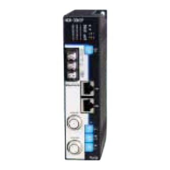
8. NOMENCLATURE 8-1. Part Identification Monitor LEDs Rear panel of converter Selection switch of the Monitor LED display contents Power terminal block (M4 screw) Communication setting switch Ethernet port 1 (LINK1) (RJ45) MAC address Ethernet port 2 (LINK2) E8:8E:60 (RJ45) xx:xx:xx Axis-1 sensor connector Product version seal... -
Page 28: Function And Name Of Indicator And Setting Area
8-2. Function and Name of Indicator and Setting Area Contents on the monitor LEDs are described in this section. NCW-3DNIP L/A1 L/A2 Data Converter Communication indicator status status indicator indicator Indicator LED color Description Indicates the operation status of NCW-3DNIP. Green / Red Communication Indicates the EtherNet/IP communication status of NCW-3DNIP. -
Page 29: Contents Of The Communication Status Indicator Area
8-2-1. Contents of the communication status indicator area Explains the overview of the Ethernet/IP communication status indicator area. For more details, refer to “11. TROUBLE SHOOTING”. Indicator Color Light status Description No power Steady Green Normal operation Flashing Green No IP address Green/Red Flashing Red A recoverable fault occurs... -
Page 30: Contents Of The Data Indicator Area
8-2-2. Contents of the data indicator area The data indicator content is changed by the display selection switch (DISP SEL). DISP SEL Display content Data Display Axis-1 position data D0-D23 Axis-2 position data D0-D23 Axis-1 preset data D0-D23 Axis-2 preset data D0-D23 Reserved Reserved Reserved... - Page 31 *4: Ethernet network transmission setting Full LINK1 Reserved Duplex Mbps Mbps Full LINK2 Reserved Duplex Mbps Mbps IP address IP Host address [IP.ADR] 8-bit - Lights status of the full duplex Light turns ON: Full Duplex Light turns OFF: Half Duplex - Either 10Mbps or 100Mbps light turns ON when it is normal.
-
Page 32: Ethernet Connector (Link1/Link2)
8-2-3. Ethernet connector (LINK1/LINK2) Ethernet communication cables are connected to these ports. port Ethernet 1 (LINK1) (RJ45) E8:8E:60 xx:xx:xx Ethernet port 2 (LINK2) (RJ45) 8-2-4. Ethernet IP address setting switch (IP) The IP address is designated by "Subnet address [NET]" and "Host address [ADR]” The Subnet address [NET] range is from 0 to F in the hex (0,…,15 in dec). -
Page 33: Ethernet/Ip Communication Setup
9-1. Procedure Before the Operation Indicates procedure before the operation Start setup Preparation -------- Refer to section 9-2. Download the EDS file (text file) from NSD web site. URL: www.nsdcorp.co.jp Set the NCW-3DHIP -------- Refer to section 9-3. communication speed and Set the NCW-3DNIP communication speed and format. -
Page 34: Preparation
③RSLogix5000 ④RSNetWorx For details of software instruction, refer to each product manual. ●EDS file If the configuration tool is needed the definition file (EDS file), download it from NSD website. URL: www.nsdcorp.com File name: EDS_Rev000000**_NSD_NCW-3D_IP_********.eds ●Hardware Setup The following figure indicates the connection of NCW-3DNIP as an example. -
Page 35: Communication Speed And Format Setting
9-3. Communication Speed and Format Setting Sets communication method for the Ethernet port (LINK1, LINK2) by the switch on the NCW-3DNIP's rear panel. Rear panel of converter Communication setting switch "AUTO (automatic detection)" is set before the shipment, so setting usually isn't required. -
Page 36: Set The Ip Address Of Ncw-3Dnip
9-4. Set the IP Address of NCW-3DNIP There are two methods for setting the IP address of NCW-3DNIP. ①Sets the subnet address “x” and host address “y” of (192.168.x.y) manually by the IP address setting switch on the NCW-3DNIP's front panel. ②Allocates the IP address for NCW-3DNIP automatically by the BOOTP/DHCP server. -
Page 37: Allocation Method Of An Ip Address By The Bootp/Dhcp Server
9-4-2. Allocation method of an IP address by the BOOTP/DHCP server The automatic allocation method of an IP address by the BOOTP/DHCP server is described below. The BOOTP/DHCP server is a stand-alone server that can set an IP address and other Transport Control Protocol (TCP) parameters. - Page 38 ●Setting Method Assign “Relation List” of the MAC address for NCW-3DNIP to the BOOTP/DHCP server before next procedures below. Check the MAC address on the panel side of NCW-3DNIP. MAC address E8:8E:60 xx:xx:xx (1) Set the Host Address rotary switch to FF (255), and then supply power to NCW-3DNIP. (2) Change the Host Address rotary switch to 00 (0), and then supply power to NCW-3DNIP once again.
- Page 39 (1) Start “BOOTP/DHCP Server2.3 software” manufactured by Rockwell Automation, Inc. (2) Configure the TCP (Transport Control Protocol) parameters From the Tools menu, choose “Network Settings”.
- Page 40 (3) Enter values on “Subnet Mask” On the “Network Settings” dialog box, enter values on “Subnet Mask”, and then click “OK”. The next items are options. - Gateway - Primary DNS - Secondary DNS - Domain Name. (4) BOOTP/DHCP request history display The “Request History”...
- Page 41 (5) Choose the appropriate module (NCW-3DNIP) Choose the appropriate module (NCW-3DNIP) in the “Request History” field, and then click “Add to Relation List”. (6) Associate the MAC address with an IP address The “New Entry” dialog box appears. Associate MAC address with IP address. Enter an IP Address, Hostname, and Description for NCW-3DNIP, and then click “OK”.
- Page 42 (7) Confirm that NCW-3DNIP is added on the "Relation list" Confirm that NCW-3DNIP is added on the "Relation list" field. Also, allocated IP address to NCW-3DNIP is displayed in the "Request History".
- Page 43 (8) Disable NCW-3DNIP requests to BOOTP/DHCP server Choose NCW-3DNIP in the “Relation List” field, and click “Disable BOOTP/DHCP”. Then, a message of “[Disable DHCP] Command successful” is displayed in the status field. When turning on the power supply again, NCW-3DNIP doesn't issue a DHCP request. Note The above operation sets Bit0-3: Startup Configuration in attribute 3 (Configuration Control) of the TCP/IP Interface object to "0: The device use the previously saved interface setting value."...
-
Page 44: Configure The Ethernet/Ip Driver
9-5. Configure the EtherNet/IP Driver Configures an Ethernet communication driver by using RSLinx Classic. Configure the EtherNet/IP Driver to the programming terminal (Windows PC) in order to set the network between the controller (1769-L30ERM/A CompactLogix5330ERM) and NCW-3DNIP. (1) Start the RSLinx Classic Software. (2) Configure Communication Drivers From the “Communications”... - Page 45 (3) Choose the EtherNet/IP Driver From the “Available Driver Types” pull-down menu, choose “EtherNet/IP Driver”. Then click “Add New …”. (4) Enter a name for the new driver The “Add New RSLinx Classic Driver” dialog box appears. Enter a name for the new driver, and click “OK”.
- Page 46 (5) Choose the Ethernet device on the EtherNet/IP network The “Configure driver” dialog box appears, and then click “Browse Local Subnet” checkbox. Choose the desired device, and click “OK”. Cancel Apply Help (6) Confirm the status with the new driver The added driver appears on the “Configure Drivers”...
- Page 47 (7) Find devices Search a device connected on the EtherNet/IP network. From the “Communications” menu, choose “RSWho”. (8) Confirm the connection between the controller and NCW-3DNIP The “RSWho” dialog box appears, and it indicates that the controller is connected with NCW-3DNIP via the EtherNet/IP network.
-
Page 48: Configuration Of Ethernet/Ip Network
9-6. Configuration of EtherNet/IP Network Configure the EtherNet/IP network by the RSLogix5000 software. RSLogix5000 is a PLC development tool software manufactured by Rockwell Automation, Inc.. 9-6-1. Configuration procedure Set the network configuration by following procedures. The procedures and settings are different whether EDS file is used or not. Start setup Without EDS file EDS file... -
Page 49: Installation Of The Eds File
9-6-2. Installation of the EDS file If EDS file isn't installed, proceed to the next “9-6-3.Creation of controller project”. (1) Starting the RSLogix5000 software (2) Choose the EDS file installation tool From the “Tools” pull-down menu, choose “EDS Hardware Installation Tool”. - Page 50 (3) Start EDS Wizard Click “Next”. Next Cancel (4) Registration of the EDS file Click the “Register an EDS files(s)” checkbox, and then click “Next”. Back Next Cancel...
- Page 51 (5) Select the EDS file Click the “Register a single file” checkbox, and then click the “Browse…”. On the “Select an EDS file” dialog box, choose the desired file and click “Open”. (6) Completion of the selected EDS file On the “Rockwell Automation’s EDS Wizard” dialog box, click “Next”. Back Next Cancel...
- Page 52 (7) EDS File Installation Test Displays EDS File Installation Test Results on the “Rockwell Automation’s EDS Wizard” dialog box. Click “Next”. Back Next Cancel (8) Graphic Image for the device It is not necessary to change Graphic Image for the device. Click “Next”. Back Next Cancel...
- Page 53 (9) Confirm the registration of NCW-3DNIP Confirm that NCW-3DNIP is successfully registered. Click “Next”. Back Next Cancel (10) Close the EDS Wizard The EDS file of NCW-3DNIP is successfully installed by the EDS Wizard. Click “OK” to close the dialog box.
-
Page 54: Creation Of A Controller Project
9-6-3. Creation of a controller project Create a new controller project for the Network. (1) Create a new controller project From the “File” menu, choose “New” to create a new controller project for the Network. - Page 55 (2) Configure a new controller project On the “New Controller” dialog box, enter the following items, and then click “OK”. - Desired controller type - Revision number of RSLogix5000 software - Project name (3) Confirmation of a new controller project A new project is created, and the controller (1769-L30ERM/A CompactLogix5330ERM) is displayed in the "I/O Configuration"...
-
Page 56: Adding Ncw-3Dnip To The Controller Project
9-6-4. Adding NCW-3DNIP to the controller project Add the NCW-3DNIP to the controller project as an I/O device. There are two ways to add NCW-3DNIP as described below. ①In case EDS file is installed (refer to section 9-6-4-1) ②In case EDS file isn’t installed (refer to section 9-6-4-2) 9-6-4-1. - Page 57 (2) The “Select Module Type” dialog box appears (3) Uncheck the “Module Type Vendor Filters” checkbox. (4) Check the “NSD Corporation” checkbox. (5) Choose NCW-3DNIP which is displayed in the "Catalog Number field”. (6) Click “Create”. (7) The “New Module” dialog box appears (8) Choose the “General”...
- Page 58 (12) The “Module Definition” dialog box appears. Choose “DINT”, and then click “OK”. (13) Choose the “Connection” tab. (14) Designate the RPI (Request Packet Interval). (15) Click “OK”. (13) (14) (15)
- Page 59 (16) "Adding NCW-3DNIP to the controller project" is completed. Confirm that NCW-3DNIP is added on "EtherNet" of the "I/O Configuration" folder.
- Page 60 9-6-4-2. In case EDS file isn’t installed (1) Right-click the “Ethernet” in the I/O Configuration folder, and choose “New Module”.
- Page 61 (2) The “Select Module Type” dialog box appears (3) Select “ETHERNET-MODULE” (4) Click “Create”. (5) The “New Module” dialog box appears (6) Enter the information of "ETHERNET-MODULE" which is newly added. - Name - Description - Comm Format - IP Address (7) Enter value to the connection parameter as follows.
- Page 62 (9) Right-click newly added "ETHERNET-MODULE", and choose the property. (10) Choose the "Connection" tab on the "Module Property Report" dialog box. (11) Designate the RPI (Request Packet Interval). Notice: RPI of NCW-3DNIP should be specified to 2.0ms or more. (12) Click “OK”. (13) “Adding NCW-3DNIP to the controller project”...
-
Page 63: Download The Project
9-6-5. Download the project Downloads the created project to the controller (1769-L30ERM/A CompactLogix5330ERM ). For downloading, the communication path must be specified to RSLogix5000 software. (1) Specifies the communication path to the controller Click “Brows ” icon (2) On the “Who Active” dialog box, choose the controller (1769-L30ERM/A CompactLogix5330ERM). (3) Click “Set Project Path”. - Page 64 (4) Turn the mode switch on the controller (1769-L30ERM/A CompactLogix5330ERM) to the “PROG” position to online. (5) Click the “Controller Status ” icon, and choose “Go Online”. (6) On the “Connected To Go Online” dialog box, click “Download”.
- Page 65 (7) On the “Download” dialog box, click “Download”. Downloading a project is started. (8) The following dialog box is displayed during downloading. The dialog box closes when the download is completed. (9) Save the project From the “File” menu, click “Save” to save all configurations described above.
- Page 66 (10) Confirm “Controller tags” Double-click the “Controller tags”. On the “Controller Tags” dialog box, I/O information of NCW-3DNIP can be confirmed. NCW-3DNIP can be accessed by the controller program.
-
Page 67: Set Parameter Of Ncw-3Dhip
9-7. Set Parameter of NCW-3DHIP Before NCW-3DNIP is used, parameters must be configured. Note In the case of using one sensor, NCW-3DNIP might not operate normally when the parameter is set by a configuration tool except RSNetWorx manufactured by Rockwell Automation, Inc. In this case, set "1 (disable)"... -
Page 68: Parameter List
9-7-1. Parameter List NCW-3DNIP has following parameters. Parameter setting values except a preset value are saved in the nonvolatile memory; therefore, NCW-3DNIP can operate with previous designated parameters after turning on the power supply again. ABSOCODER Object (Class ID: 0x64) Axis Parameters Descriptions... -
Page 69: Parameters Setting Procedure
9-7-2. Parameters Setting Procedure Use the RSNetWorx software to set parameters. NCW-3DNIP (after the version 2.01) can set parameters by using the web server function. Products with the software version mark put on the products panel after " B " support this function. Refer to "8-1."... - Page 70 (3) Browse Network On the “Browse for Network” dialog box, choose a desired network. (4) Click “OK”. (5) On the “Browsing network...” dialog box, the progress of searching network is shown.
- Page 71 (6) Confirm your network device The configured devices are indicated in network. Confirms the network at which the controller (1769-L30ERM/A CompactLogix5330ERM) is connected to NCW-3DNIP. (7) Start “Class Instance Editor” Right-click NCW-3DNIP, and choose “Class Instance Editor”.
- Page 72 (8) Confirm the WANING on “Class Instance Editor” dialog box, and click “Yes”.
- Page 73 (9) Set the parameter There are parameters which are for axis-1 and axis-2. Set the following contents. A) Position Data Increase Direction B) Axis Unavailable C) Error Clear B) and C) usually don’t need to be set. Set them if you need. For the setting, enter the setting values from (a) to (f) in the dialog “Class Instance Editor”, and click the “Execute”...
- Page 74 (10) Confirm “Position Data Increase Direction” setting "The execution was completed." is displayed in the "Data received from the device" field when "Position Data Increase Direction" is set correctly. Confirm both axes. (10) (11) Specify “Preset Value” "Preset Value" is specified to each two settings (for axis-1 and for axis-2). Enter a setting value in "Class Instance Editor"...
- Page 75 (12) Confirm “Preset Value” "The execution was completed." is displayed in the "Data received from the device" field when "Preset Value" is set correctly. Confirm both axes. (12)
-
Page 76: Confirm Position Data Of Ncw-3Dnip
9-8. Confirm Position Data of NCW-3DNIP All settings are completed, and NCW-3DNIP is ready to use. Double-click the “Controller tags” of RSLogix5000. The “Controller Tags” dialog box appears. The position data can be confirmed by the tag of NCW-3DNIP. The tags which indicate each position data are as follows. Axis-1 Position Data →... -
Page 77: Cip Implicit Messaging (I/O Connection)
9-9. CIP Implicit Messaging (I/O Connection) NCW-3DNIP has the "Exclusive-Owner Connection" for the unicast connection which can connect with the real-time I/O communication connection. It lets control the I/O data of NCW-3DNIP. The connection summary and data format are described below. 9-9-1. - Page 78 (2) Scanner -> Slave (Output) Data Format (Size: 16-byte) Offset Address Data Format (Byte) Size Name Description WORD Axis-1 Control Axis-1 Control Flags Description Reserved ERRCLR (Error Clear Command) Clears an error that is monitored from Axis-1 Status. 0: Not clear an error 1: Clear an error PRESET (Preset Command) Presets a position data for Axis-1.
- Page 79 (3) Slave -> Scanner (Input) Data Format (Size: 28-byte) Offset Address Data Format (Byte) Size Name Description DWORD System Status NCW-3DNIP Diagnosis Status Description NRDY (Internal Error) Indicates that an internal error of NCW-3DNIP occurred. The hardware might have malfunction if the converter doesn't operate normally after restarting the power supply.
- Page 80 Continued from the previous page Offset Address Data Format (Byte) Size Name Description UDINT Axis-2 Position Axis-2 Position data Shows the Axis-2 Position data. UDINT Reserved Reserved WORD Axis-2 Status Axis-2 Status Description SE (Sensor Error) Indicates that a SSE/SPF/DE occurred. 0: No error 1: Error Reserved...
- Page 81 (4) Preset procedure Indicates PRESET procedure of the current position value which is using the I/O communication data (Implicit message). Preset Value Preset Value 100ms or more RPI or more PRESET RPI or more (Control Flag bit-7) RPI or less Position Data Old current position data PRESET Position data...
-
Page 82: Device Level Ring (Dlr) Function
9-10. Device Level Ring (DLR) Function NCW-3DNIP can be used as a ring node for device level ring (DLR) function. All ring nodes on the network must support DLR function when using this function. All settings of DLR function are done by "Supervisor node". NCW-3DNIP doesn't need any setting. Refer to the "Supervisor node manual in-use"... -
Page 83: Inspection
10. INSPECTION The inspection should be conducted once every 6 months to a year. Any inspected items which do not satisfy the criteria shown below should be repaired Inspection Inspection Description Criteria Remark item Measure the voltage fluctuation at the power Power supply supply terminal block of the converter to Within 21.6V to 26.4VDC range... -
Page 84: Trouble Shooting
11. TROUBLE SHOOTING Explains each error which is detected by NCW-3DNIP. 11-1.Check Methods during an Error Is Occurred Error details can be checked by the indicator light status of NCW-3DNIP or using the following software (RSLogix5000 or RSNetWorx). ①Each status in Implicit (Input) message (Use RSLogix5000) ②Instance 0x01 and 0x02 of the ABSOCODER object 0x64 in the Explicit message (Use RSNetWorx) -
Page 85: Cip General Status Code
11-3. CIP General Status Code The following table lists the Status Codes that may be present in the General Status Code field of an Error Response message. Note that the Extended Code Field is available for use in further describing any General Status Code. For the Extended Status code, refer to “11-4.”. - Page 86 (2/3) General Status Status Name Description of Status Code (in hex) Service fragmentation sequence The fragmentation sequence for this service is not currently active for not in progress this data. The attribute data of this object was not saved prior to the requested No stored attribute data service.
- Page 87 (3/3) General Status Status Name Description of Status Code (in hex) This error code may only be reported by DeviceNet Group 2 Only Group 2 only server general failure servers with 4K or less code space and only in place of Service not supported, Attribute not supported and Attribute not settable.
-
Page 88: Cip Extended Status Code
11-4. CIP Extended Status Code Status Codes may be present in the General Status and the Extended Status of an Error Response message. 11-4-1. Connection Manager Object Instance Extended Status Code The error codes are returned with the response to a Connection Manager Service Request that resulted in an error. - Page 89 (2/3) Extended Status Description of Status Code (in hex) 0127 Invalid originator to target network connection size 0128 Invalid target to originator network connection size 0129 Invalid configuration application path 012A Invalid consuming application path 012B Invalid producing application path 012C Configuration symbol does not exist 012D...
-
Page 90: Extended Status Codes For Protocol Stack (Communication Control Part)
(3/3) Extended Status Description of Status Code (in hex) 0810 No target application data available 0811 No originator application data available 0812 Node address has changed since the network was scheduled 0813 Not configured for off-subnet multicast 0814 Invalid produce / Consume data format 0815 - FCFF Reserved FD00 - FFFF... -
Page 91: Ncw-3Dnip Indicator
11-5. NCW-3DNIP Indicator 11-5-1. Status indicator (MS/NS) Error contents can be checked by lighting status of the status indicator (MS/NS) when an error occurs. Check the contents and take appropriate measures. Light status Name Cause and Countermeasure Normal operation Indicates that it is in the normal communication. Green Green Flashing... -
Page 92: Link Status Indicator (L/A1・L/A2)
11-5-2. Link status indicator (L/A1・L/A2) The Link Status indicator (L/A1, L/A2) monitors communication state. L/A1: Monitors the Ethernet port 1 state. L/A2: Monitors the Ethernet port 2 state. Light status Name Cause and Countermeasure L/A1, L/A2 No link Indicates Link is not established. Link Indicates Link is established. -
Page 93: Reset Service
11-6. Reset Service The state of NCW-3DNIP (slave) can be reset by using a configuration tools or EtherNet/IP scanner (master) if EhterNet/IP communication is available. Use Reset (ID: 0x05) in an Instance Service (InstanceID: 0x01) of the Identity object (ClassID: 0x01), and the device can be reset. - Page 94 - MEMO -...
-
Page 95: Store Of Maintenance Information
12. STORE OF MAINTENANCE INFORMATION NCW-3DNIP can store maintenance information to the Info Maintenance object (Class ID: 0xC07). The maintenance information should be store if it is required. Stored information can be checked when doing periodic maintenance NCW-3DNIP or having an error. For more details, refer to "APPENDIX 2-12. -
Page 96: Absocoder Sensor Check List
13. ABSOCODER SENSOR CHECK LIST ●Applicable ABSOCODER sensor models MRE-32SP062 MRE-G[ ]SP062 [ ]: 64, 128, 160, 256, 320 ●Connection configuration ●Connector appearance and pin position NCW-3DNIP ABSOCODER sensor View A Extension sensor MRE-32SP062 MRE-G[ ]SP062 Checks at Point B should be carried out with Point A connected. ●... - Page 97 *1: If checks are done at Point B, the measurement value is [Standard coil resistance + extension sensor cable resistance (cable length (m) x 0.2 (Ω))]. The resistance value of the NSD special cable is 0.2Ω/m (loop resistance). Consider resistance variations due to temperature, which, relative to the standard temperature (25 increases 0.4% when the temperature rises 1...
-
Page 98: Ce Marking
14. CE MARKING This product conforms to the EMC Directive. 14-1. EMC Directives It is necessary to do CE marking in the customer’s responsibility in the state of a final product. Confirm EMC compliance of the machine and the entire device by customer because EMC changes configuration of the control panel, wiring, and layout. -
Page 99: Measures For Emc Compliance
14-4. Measures for EMC Compliance Describes measures for EMC compliance when testing the compatibility verification. ●LAN cable (Communication cable for EtherNet/IP) A CAT-5e STP straight cable was used as the LAN cable. The LAN cable was covered with the shielded zippertubing, and the shield was grounded. Zippertubing Model Manufacturer... -
Page 100: Appendix 1. Cip Object Model
APPENDIX 1. CIP OBJECT MODEL The following figure illustrates the CIP object model of the NCW-3DNIP. Info Log Non-volatile memory ABSOCODER Parameter Class: 0xC5 Object Object Object Class: 0x64 Class: 0x0F Info Diagnosis Object Identity Class: 0xC6 Object Class: 0x01 Info Maintenance Object Class: 0xC7... -
Page 101: Appendix 2. Details Of Cip Object
Instance Attribute (Class ID: 0x01, Instance ID: 0x01) Access Name Data Type Description 0x01 Vendor ID ○ UINT Indicates the product vendor ID. (230: NSD Corporation) - 0x02 Device Type ○ UINT Indicates the product device type. (43: Generic Device) - 0x03 Product Code ○... - Page 102 Instance Service (Class ID: 0x01, Instance ID: 0x01) Name Description 0x01 Get_Attribute_All Read out all attribute values from NCW-3DNIP. 0x05 Reset Reset service The Reset service parameters are the following; 0: Restart 1: All NCW-3DNIP parameters' setting is redesignated to initial values (factory setting), and restart.
- Page 103 ●Identity (ClassID: 0x01) State transition diagram of object The Identity object defines the NCW-3DNIP’s behavior. Power Loss (from any state) Non-Existent (Off) Power Applied Identity Object Reset Service Device Self-Test (from any state except Major Unrecoverable Fault) Error detection (Flashing Red / Flashing Green) Passed Tests Minor Fault...
-
Page 104: Appendix 2-2. Message Router Object (Class Id: 0X02)
APPENDIX 2-2. Message Router Object (Class ID: 0x02) All communication messages are processed, and then they are sorted to proper objects. Following tables indicate specifications of the Message Router object. The Message Router object has one instance; however, all attribute isn’t opened to the public. Class Attribute (Class ID: 0x02) Access Name... -
Page 105: Appendix 2-3. Assembly Object (Class Id: 0X04)
APPENDIX 2-3. Assembly Object (Class ID: 0x04) This object is assembled for ABSOCODER. I/O message data for the NCW-3DNIP's Exclusive-Owner connection can be read or written. Following tables indicate specifications of the Assembly object. NCW-3DNIP has the following Assembly object instances. 0x65: For Exclusive-Owner (Input) Connection 0x66: For Exclusive-Owner (Output) Connection 0x67: For Exclusive-Owner (Configuration) Connection... - Page 106 Instance Attribute (Class ID: 0x04, Instance ID: 0x67) Access Name Data Type Description 0x03 Data ○ USINT[0] Indicates the Configuration (Exclusive-Owner) data. - *: The general status code “0x0E (not settable) will be returned to the EtherNet/IP master if the Set operation is done.
-
Page 107: Appendix 2-4. Connection Manager Object (Class Id: 0X06)
APPENDIX 2-4. Connection Manager Object (Class ID: 0x06) The Connection Manager object manages the communication status, and has one instance. Following tables indicate specifications of the Connection Manager object. Class Attribute (Class ID: 0x06) Access Name Data Type Description 0x01 Revision ○... - Page 108 Instance Service (Class ID: 0x06, Instance ID: 0x01) Name Description 0x01 Get_Attribute_All Read out all attribute values from NCW-3DNIP. 0x0E Get_Attribute_Single Read out one attribute value from NCW-3DNIP. 0x4E Forward_Close Close the connection. 0x54 Forward_Open Open the connection.
-
Page 109: Appendix 2-5. Parameter Object (Class Id: 0X0F)
APPENDIX 2-5. Parameter Object (Class ID: 0x0F) Parameter object provides parameter information of NCW-3DNIP. Following tables indicate specifications of the Parameter object. This is objects for parameters which are used with NCW-3DNIP. Class Attribute (Class ID: 0x0F) Access Name Data Type Description 0x01 Revision... - Page 110 Instance Attribute (Class ID: 0x0F, Instance ID: 0x01) Access Name Data Type Description 0x01 Parameter Value ○ ○ BOOL Parameter value (Axis-1 parameter :Axis Unavailable) 0x02 Link Path Size ○ USINT - Packed 0x03 Link Path ○ "20 64 24 01 30 64" -...
- Page 111 Instance Attribute (Class ID: 0x0F, Instance ID: 0x03) Access Name Data Type Description Parameter value (Axis-1 parameter: Position Data 0x01 Parameter Value ○ ○ BOOL Increase Direction) 0x02 Link Path Size ○ USINT - Packed 0x03 Link Path ○ "20 64 24 01 30 0C" -...
- Page 112 Instance Attribute (Class ID: 0x0F, Instance ID: 0x05) Access Name Data Type Description 0x01 Parameter Value ○ ○ BOOL Parameter value (Axis-2 parameter: Axis Unavailable) 0x02 Link Path Size ○ USINT - Packed 0x03 Link Path ○ "20 64 24 02 30 64" -...
- Page 113 Instance Attribute (Class ID: 0x0F, Instance ID: 0x07) Access Name Data Type Description Parameter value (Axis-2 parameter: Position Data 0x01 Parameter Value ○ ○ BOOL Increase Direction) 0x02 Link Path Size ○ USINT - Packed 0x03 Link Path ○ "20 64 24 02 30 0C" -...
- Page 114 Instance Service (Class ID: 0x0F, Instance ID: 0x01,0x02,0x03,0x04,0x05,0x06,0x07,0x08) Name Description 0x01 Get_Attribute_All Read out all attribute values from NCW-3DNIP. 0x0E Get_Attribute_Single Read out one attribute value from NCW-3DNIP. 0x10 Set_Attribute_Single Write one attribute value to NCW-3DNIP.
-
Page 115: Appendix 2-6. Absocoder Object (Class Id: 0X64)
APPENDIX 2-6. ABSOCODER Object (Class ID: 0x64) ABSOCODER object provides setting information of the absolute encoder (ABSOCODER). Following tables indicate specifications of the ABSOCODER object. The ABSOCODER object has two instances for 2-axis NCW-3DNIP. Class Attribute (Class ID: 0x64) Access Name Data Type Description... - Page 116 Instance Attribute (Class ID: 0x64, Instance ID: 0x01[For axis-1], 0x02[For axis-2] ) Access Name Data Type Description 0x01 Number of Attributes ○ USINT Indicates Numbers of Attributes that are supported this - product. Returns the Number of Attributes “9”. 0x02 Attribute List ○...
-
Page 117: Appendix 2-7. Qos Object (Class Id: 0X48)
APPENDIX 2-7. QoS Object (Class ID: 0x48) The QoS object provides relative priority setting information of different transmission traffics. A transmission traffic priority can be adjusted by a managed switch on the network when the relative priority is set. The relative priority is specified by the Qos object attribute setting. NCW-3DNIP uses DiffServ (QoS) (redefinition of the “ToS”... - Page 118 Instance Attribute (Class ID: 0x48, Instance ID: 0x01) Access Name Data Type Description 0x04 DSCP Urgent ○ ○ USINT Set the DSCP value for CIP transport class 0/1 messages with Urgent priority. Default: 55 (110 11 1b) This setting is invalid for NCW-3DNIP. 0x05 DSCP Scheduled ○...
- Page 119 ●Complement (DSCP value) A packet priority allocation is classified for each DSCP value by a definition is called “PHB( Per-Hop Behavior)". Default values for general EtherNet and EtherNet/IP are shown below DSCP value Description Bit5-3: high priority class Bit2-1: packet discard rate Bit0: Standard / Test ■General Ethernet definition AF11...
-
Page 120: Appendix 2-8. Tcp/Ip Interface Object (Class Id: 0Xf5)
APPENDIX 2-8. TCP/IP Interface Object (Class ID: 0xF5) The TCP/IP interface object provides Ethernet TCP/IP interface information. The TCP/IP Interface Object provides the mechanism to configure the NCW-3DNIP’s TCP/IP network interface (IP address, network mask, and gateway address). Following tables indicate specifications of the TCP/IP Interface object. The TCP/IP Interface object has one instance. - Page 121 (2/4) Access Name Data Type Description 0x02 Configuration Capability ○ DWORD Fixed at 0x00000075 - The following table indicates the function which is supported by NCW-3DNIP. Description BOOTP Client 1: Indicates that NCW-3DNIP is capable of obtaining its network configuration via BOOTP. DNS Client 0: Indicates NCW-3DNIP can not obtain host names from DNS server.
- Page 122 (3/4) Access Name Data Type Description 0x04 Physical Link Object ○ Structure Identifies an object (Ethernet Link Object) related to the - physical interface. The path indicates the Instance 1 of the Ethernet Link Object class. UINT Path Size Packed Path "20 F6 24 01"...
- Page 123 (4/4) Access Name Data Type Description 0x09 Mcast Config Structure NCW-3DNIP doesn't support this attribute. - - USINT USINT UINT UDINT 0x0A Select ACD BOOL NCW-3DNIP doesn't support this attribute. - - 0x0B LastConflictDetected Structure NCW-3DNIP doesn't support this attribute. -...
-
Page 124: Appendix 2-9. Ethernet Link Object (Class Id: 0Xf6)
APPENDIX 2-9. Ethernet Link Object (Class ID: 0xF6) The Ethernet Link object provides Ethernet Interface’s MAC address, communication speed and format status information. Following tables indicate specifications of the Ethernet Link object. NCW-3DNIP has two ports, so the Ethernet Link object has two instances. Class Attribute (Class ID: 0xF6) Access Name... - Page 125 Instance Attribute (Class ID: 0xF6, Instance ID: 0x01, 0x02) (1/3) Access Name Data Type Description 0x01 Interface Speed ○ UDINT NCW-3DNIP’s current state - Speed value (Mbps): 0, 10, 100, 1000, and etc… 0x02 Interface Flag ○ DWORD NCW-3DNIP’s current state -...
- Page 126 (2/3) Access Name Data Type Description 0x04 Interface Counters Structure NCW-3DNIP doesn't support this attribute. - - UDINT UDINT UDINT UDINT UDINT UDINT UDINT UDINT UDINT UDINT UDINT 0x05 Media Counters Structure NCW-3DNIP doesn't support this attribute. - - UDINT UDINT UDINT UDINT...
- Page 127 (3/3) Access Name Data Type Description identifier 0x0A Interface Label ○ SHORT_ Interface - STING Instance 0x01: "Port1" Instance 0x02: "Port2" 0x0B Interface Capability ○ Structure Interface function - DWORD [Capability Bits] The values (Bit0:0, Bit1:1, Bit2:1, and Bit3:0) are fixed. Indicates interface functions other than Speed / Duplex.
-
Page 128: Appendix 2-10.Info Log Object (Class Id: 0Xc5)
APPENDIX 2-10.Info Log Object (Class ID: 0xC5) Info Log object provides NCW-3DNIP operation and error histories (max.32). Stored information is saved in the non-volatile memory. Following tables indicate specifications of the Info Log object. Info Log object has one instance. Class Attribute (Class ID: 0xC5) Access Name... - Page 129 ●History Message Lists (1/2) History message code (Hex) History message Message details 0x00000001 Power ON The power was applied. 0x00000002 Power FAIL A low power supply was detected. 0x00000003 - 0x0000000E - 0x0000000F IP Address CONFLICT IP Address CONFLICT was detected. 0x00000010 LINK1 Settings - AUTO LINK1 port settings is “...
- Page 130 (2/2) History message code (Hex) History message Message details 0x00000053 Access to a Parameter OBJECT A Parameter OBJECT was accessed. 0x00000054 Access to a QoS OBJECT A QoS OBJECT was accessed. 0x00000055 Access to an ABSOCODER OBJECT An ABSOCODER OBJECT was accessed. 0x00000056 -...
-
Page 131: Appendix 2-11. Info Diagnosis Object (Class Id: 0Xc6)
APPENDIX 2-11. Info Diagnosis Object (Class ID: 0xC6) This object provides NCW-3DNIP diagnosis information. Following tables indicate specifications of the Info Diagnosis object. The Info Diagnosisobject has one instance. Class Attribute (Class ID: 0xC6) Access Name Data Type Description 0x01 Revision ○... -
Page 132: Appendix 2-12. Info Maintenance Object (Class Id: 0Xc7)
APPENDIX 2-12. Info Maintenance Object (Class ID: 0xC7) Stores NCW-3DNIP maintenance information in this object. The maintenance information is saved in the non-volatile memory. Following tables indicate specifications of the Info Maintenance object. The Info Maintenance object has one instance. Class Attribute (Class ID: 0xC7) Access Name... -
Page 133: Appendix 2-13. Device Level Ring (Dlr) Object (Class Id: 0X47)
APPENDIX 2-13. Device Level Ring (DLR) Object (Class ID: 0x47) This object can confirm the state of the NCW-3DNIP’s Device Level Ring. Following tables indicate specifications of the Device Level Ring object. The Device Level Ring object has one instance. Class Attribute (Class ID: 0x47) Access Name... - Page 134 Instance Service (Class ID: 0x47, Instance ID: 0x01) Name Description 0x01 Get_Attribute_All Read out all attribute values from NCW-3DNIP. Attribute ID 1 to 8 and 10 to12 can be read out. Attribute ID 3 to 8 and 11 aren't supported, thus initial values are read out. 0x0E Get_Attribute_Single Read out one attribute value from NCW-3DNIP.
-
Page 135: Appendix 3. Web Server Function
APPENDIX 3. WEB SERVER FUNCTION NCW-3DNIP can use the web server function. The web server function can set and check the user management and information. The web server function is supported after version 2.01. Products with the software version mark put on the products panel after " B " support. Refer to "8-1."... -
Page 136: Appendix 3-1. Login Procedures
APPENDIX 3-1. Login Procedures Login NCW-3DNIP for using the web server function. ●Login procedures 1. Enter NCW-3DNIP's IP address to the address bar of the internet browser. 2. A login window appears. 3. Enter "admin" to the user name and password fields, click "Login" button. (*: The password can be changed at "user setting window".) NCW-3DNIP’s IP address ●User name... -
Page 137: Appendix 3-2. User Management Function
APPENDIX 3-2. User management function User's setting operation can be restricted at the management function. Click "User Setting" on the menu. A User Setting window appears. ●User and access right display Settable :〇 No display: Impossible to settings (Only for reference) ●Settable Selects the access right for each user. -
Page 138: Appendix 3-3. Setting / Reference Display
APPENDIX 3-3. Setting / Reference display (1) Menu “Identity Object (ClassID: 0x01)” - Reference of the identity information NCW-3DNIPMP... - Page 139 (2) Menu “Absocoder Object (ClassID: 0x64)” - References and settings of ABSOCODER's parameter and status Note When setting parameters, switch the operation mode of the host PLC to program mode (PROG). Cannot be set in run mode (RUN). This operation is performed by using the PLC's configuration tool (a PLC development tool software). *: Depending on the PLC model, this operation can also be performed by the mode selection switch on the CPU card.
- Page 140 (3) Menu “TCP/IP Object (ClassID: 0xF5)” - References and settings of Ethernet TCP/IP's parameter and status (4) Menu “Ethernet Link Object (ClassID: 0xF6)” - Reference of the Ethernet Link status...
- Page 141 (5) Menu “Info Log Object (ClassID: 0xC5)” - Reference and settings of the log information (6) Menu “Info Maintenance Object (ClassID: 0xC7)” - Reference and settings of the maintenance information...
- Page 142 (7) Menu “Reset Service” - Reset operation of NCW-3DNIP The reset operation can be selected from the following three types; Type of Reset Description Restart Restart All NCW-3DNIP parameters' setting is redesignated to initial values Factory setting (factory setting), and restart. Factory setting except All NCW-3DNIP parameters' setting is redesignated to initial values communication parameter...
- Page 144 Manufacturer NSD Corporation 3-31-28, OSU, NAKA-KU, NAGOYA, JAPAN 460-8302 Distributor NSD Trading Corporation 3-31-23, OSU, NAKA-KU, NAGOYA, JAPAN 460-8302 Phone: +81-52-261-2352 Facsimile: +81-52-252-0522 URL: www.nsdcorp.com E-mail: foreign@nsdcorp.com Copyright©2023 NSD Corporation All rights reserved.
Need help?
Do you have a question about the ABSOCODER NCW-3DNIPMP and is the answer not in the manual?
Questions and answers