
Related Manuals for NSD ABSOCODER NCW-3DHPRV1R


Summary of Contents for NSD ABSOCODER NCW-3DHPRV1R
- Page 1 ZEF005670603 For Iron and Steel Industry ABSOCODER Converter For PROFIBUS-DP NCW-3DHPRV1R Specifications & Instruction Manual Applicable sensor VRE-P061 VRE-P074 VRE-P097 VRE-P101...
-
Page 3: General Safety Rules
- Be sure to store the controller in designed temperature and humidity CAUTION range, and do not exposed to direct sunlight. - Be sure to consult with NSD when the controller is stored for long - Be sure to handle the controller as industrial waste while periods. -
Page 4: Revision History
REVISION HISTORY The Document No. appears at the upper right of this manual's cover page. Document No. Date Revision Description ZEF005670600 20, Oct., 2015 1st Edition Japanese document: ZEF005670500 ZEF005670601 13, Nov., 2015 2nd Edition Japanese document: ZEF005670501 ZEF005670602 8, Mar., 2016 3rd Edition Japanese document: ZEF005670502 ZEF005670603... - Page 5 - MEMO -...
-
Page 6: Table Of Contents
CONTENTS 1. OVERVIEW ..........................1 1-1. Features ................................1 2. MODEL SELECTION WHEN ORDERING ................2 3. SPECIFICATIONS ........................4 3-1. Converter Specifications ............................ 4 3-2. ABSOCODER Sensor Specifications ......................... 6 3-3. Extension Sensor Cable Specification ....................... 8 4. DIMENSIONS .......................... 9 4-1. -
Page 7: Overview
1. OVERVIEW NCW-3DHPRV1R converter (hereafter called NCW-3DHPR) can be combined with a single-turn type of ABSOCODER sensor (VRE) to detected the machine position. This converter communicates with programmable logic controllers by PROFIBUS-DP. ●GSD file This product requires a definition file (GSD file) which is installed to the configuration tool. Download GSD file from the following URL. -
Page 8: Model Selection When Ordering
(1) Converter Slave Slave Slave Power Supply +24V Ground (3) Extension sensor cable (2) ABSOCODER sensor (4) Option In the case of using the NSD special cable Connector type RB-01 VRE-P061 L type flange for VRE-P074 VRE-P061 VRE-P097 VRE-P101 In the case of using the commercially available cable... - Page 9 (NJW-2012-PM8, manufacturer: Nanaboshi Electric Mfg.Co,Ltd.) P: Large connector for JKPEV-S cable (NWPC-4012-Ad12, manufacturer: Nanaboshi Electric Mfg.Co,Ltd.) R: Crimping terminals for JKPEV-S cable and the NSD special cable (R1.25-4) [L]: Interconnecting sensor cable length (m): 2, 5,10, 20 G: Silicon oil injected, no code: no oil injected ◆Extension sensor cable...
-
Page 10: Specifications
3. SPECIFICATIONS 3-1. Converter Specifications (1) General specification Items Specifications Power supply voltage 24VDC±10% (including ripple) Power consumption 10W or less 20 M-Ohms or more between external DC power terminals and ground Insulation resistance (by 500 VDC insulation resistance tester) 500 VAC, 60Hz for 1 minute between external DC power terminals and Withstand voltage ground... -
Page 11: Profibus-Dp (V0)
(3) PROFIBUS-DP specification Items Specifications Interface PROFIBUS-DP (V0) 9.6k,19.2k,45.45k,93.75k,187.5k,500k,1.5M,3M,6M,12M [Baud] Baud rates (Automatic Baud Rate Identification) Supported Global Control Freeze,Sync Set_Slave_Address not supported Station type modular device Max_Module Max_Input_length 8 [bytes] Max_output_length 8 [bytes] Extended diagnostic information 8 [bytes] Ext_Module_Prm_Data_Length 7 [bytes] Others Refer to the GSD file for details... -
Page 12: Absocoder Sensor Specifications
3-2. ABSOCODER Sensor Specifications (1) VRE-P061, VRE-P074 Items Specifications Sensor model VRE-P061 VRE-P074 Total number of turns Number of divisions 8192 (2 Flange-mount type: 3.5+0.1 x cable length (m) kg Base-mount type: 5.5+0.1 x cable Mass 1.3kg length (m) kg Face-mount type: 3.0+0.1 x cable length (m) kg Linearity error... - Page 13 (2) VRE-P097, VRE-P101 Items Specifications Sensor model VRE-P097 VRE-P101 Total number of turns Number of divisions 8192 (2 Mass 6.5+0.1 x cable length (m) kg Linearity error 0.7°Max. Moment of inertia GD /4(J) 3.3 x 10 kg・m (3.4 x 10 kgf・cm・s Starting torque 9.8 x 10...
-
Page 14: Extension Sensor Cable Specification
8-core, 2 pairs without shield + 2 pairs with shield Color Gray Black Heat treatment and Extensible for long Advantage Superior flexibility; ideal for moving place flexible; ideal for distances moving place [Remark] Contact your NSD representative when the extension cable combines different types of cables. -
Page 15: Dimensions
4. DIMENSIONS 4-1. Converter Dimension Units: mm Mounting hole DIN rail... -
Page 16: Absocoder Sensor Dimensions
4-2. ABSOCODER Sensor Dimensions (1) VRE-P061FK[ ] (Flange-mounting type) Units: mm (2) Option: RB-01 L-type flange for VRE-P061... - Page 17 (3) VRE-P074FK[ ] (Flange-mount type) Units: mm (4) VRE-P074LK[ ] (Base-mount type) (5) VRE-P074MK[ ] (Face-mount type)
- Page 18 (6) VRE-P097FK[ ] (Flange-mount type) Units: mm (7) VRE-P097LK[ ] (Base-mount type)
- Page 19 (8) VRE-P101FK[ ] (Flange-mount type) Units: mm (9) VRE-P101LK[ ] (Base-mount type)
-
Page 20: Extension Sensor Cable Dimensions
4-3. Extension Sensor Cable Dimensions (1) 4P-S-0144-[L] / 4P-RBT-0144-[L] / 4P-URT-0144-[L] Units: mm NOTE: [L] is given in terms of meter. (2) 4P-S-4344-[L] / 4P-RBT-4344-[L] / 4P-URT-4344-[L] / 4P-HRT-4344-[L] NOTE: [L] is given in terms of meter. (3) 4P-S-0155-[L] / 4P-RBT-0155-[L] / 4P-URT-0155-[L] NOTE: [L] is given in terms of meter. -
Page 21: Checking The Contents Of The Shipping Case
5. CHECKING THE CONTENTS OF THE SHIPPING CASE Open the packing case, and verify that all items are present. When extension sensor cables are ordered, they are packed separately. ① ② ①Converter······································································· 1 unit ②Manual (Simple edition) ···················································· 1 piece... -
Page 22: Installation
6. INSTALLATION 6-1. Converter Installation Conditions and Precautions When installing the converter, the following conditions and precautions should be observed. -Installation Site (1) Avoid sites where the unit is exposed to direct sunlight. (2) The ambient temperature should never exceed a 0 to 55°C range. (3) The ambient humidity should never exceed a 20 to 90% RH range. -
Page 23: Absocoder Sensor Installation Conditions And Precautions
6-2. ABSOCODER Sensor Installation Conditions and Precautions The ABSOCODER installation procedures and precautions are described in this section. ● Handling of Turn-type ABSOCODER Sensor Item Explanation (1) Main unit (2) Cable ● Mounting of Turn-type ABSOCODER Sensor Item Explanation Precaution (1) Mounting For details regarding mounting dimensions, refer to each ABSOCODER dimensions. - Page 24 ● Mounting of Turn-type ABSOCODER Sensor Item Explanation Precaution (1) Coupling of machine A “direct-link” format will shaft and sensor result in shaft fatigue shaft and / or breakage after long periods. Therefore, be sure to use a coupling device to link the shafts.
- Page 25 ● Coupling of Turn-type ABSOCODER Sensor Item Explanation Precaution (1) Coupling device The selection of a larger selection precaution coupling than necessary will increase the shaft load which is caused by the mounting error amount. Excessive force applied to the shaft can deform the coupling and reduce durability.
-
Page 26: Wiring
7. WIRING 7-1. Connection between Converter and ABSOCODER Sensor The maximum extension sensor cable length varies according to the ABSOCODER sensor and cable model being used. For more details refer to “3-2. ABSOCODER Sensor Specifications". -Wiring Precautions (1) The sensor cable should be clamped as shown in the right figure to prevent excessive tension from Cable clamp being applied to the cable connectors. -
Page 27: Connection Configure Example Of The Sensor Cable
7-1-1. Connection configure example of the sensor cable ● In the case of using the NSD special cable ABSOCODER sensor Extension sensor cable Converter... - Page 28 ● In the case of using the commercially available cable (JKPEV-S 1.25mm2×5P) and connecting with crimping terminals Please install the crimping terminals by customers Converter JKPEV-S Cable cross section ABSOCODER sensor Commercially available cable NSD special cable Crimping terminal Crimping terminal (R1.25-4) (R1.25-4) Crimping terminal (R1.25-4)
- Page 29 Please install the connector by customers Converter JKPEV-S Cable cross section ABSOCODER sensor Commercially available cable NSD special cable ABSOCODER sensor JKPEV-S cable NSD special cable Connector pin No. Connector pin No. and wire color Connector pin No.
-
Page 30: Power Supply Connection
7-2. Power Supply Connection The power supply should be connected as described below: ●Power Supply - Choose the power supply capacity which is more than twice the power consumption of the converter. The power consumption of the converter is 10W or less. Over +24VDC Power... -
Page 31: Nomenclature
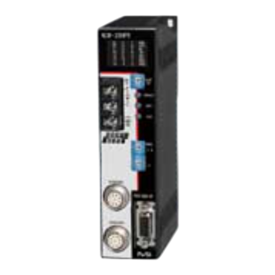
8. NOMENCLATURE 8-1. Part Identification Monitor LEDs Selection switch of the Monitor LED Power terminal block display contents (M4 screw) Error clear button Axis-1 zero setting button Axis-2 zero setting button PROFIBUS-DP node address setting switch Axis-1 sensor connector PROFIBUS-DP connector Axis-2 sensor connector... -
Page 32: Function And Name Of Display And Setting Area
8-2. Function and Name of Display and Setting Area 8-2-1. Display contents of the monitor LEDs Display contents on the monitor LEDs is described in this section. Display Description ON when the power supply is functioning normally. ON when PROFIBUS-DP communication is functioning normally. DTEX OFF when the converter fails to establish communication with the master by the PROFIBUS-DP configuration tool (PROFIBUS configuration software). - Page 33 Selection switch of the Monitor LED display contents (DISP SEL) DISP.SEL Display content Axis-1 position data D0-D23 Selection switch of the Axis-2 position data D0-D23 Monitor LED display contents Axis-1 preset data D0-D23 Axis-2 preset data D0-D23 Previous axis-1 preset data Previous axis-2 preset data Sensor type Converter diagnosis data...
-
Page 34: Error Clear Button (Clr)
8-2-2. Error clear button (CLR) Press the error clear button (CLR) on the front panel to clear the errors. Error clear button 8-2-3. Zero setting button (ZPS1, ZPS2) The position data can be changed to "0" by pressing the zero setting button (ZPS1/ZPS2) on the front panel. Move the machine to the zero-point position with no error, and press the zero setting button. -
Page 35: Profibus-Dp Communication
9. PROFIBUS-DP Communication Master: PLC etc. Slave: NCW-3DHPR 9-1. Position Data (Input Data: Slave → Master) The position data detected by the ABSOCODER sensor can be read as Input Data by the master. byte bit7 bit6 bit5 bit4 bit3 bit2 bit1 bit0 offset... -
Page 36: Preset Data (Output Data: Master → Slave)
9-2. Preset Data (Output Data: Master → Slave) The master can change the position data to any desired value by performing the preset function using Output Data. The changed position data is stored in the converter's non-volatile memory. Therefore, there is no need to do the preset function each time the power is turned on. - Page 37 (1) Preset timing The position data is changed by the preset data (PRD0-PRD12) and PRESET signal (1 bit) which are written from the master. The response time from the point when the PRESET signal changes from “0” to “1”, until the preset setting occurs, is shown below.
- Page 38 (2) Program for preset function A program example which executes a preset function is shown below. Conditions The following signal assignments are used to control the NCW-3DHPR. Axis-1 preset instruction to NCW-3DHPR ······························ I20.0 NCW-3DHPR's axis-1 position data display ··························· Q30.0 ~ Q33.7 NCW-3DHPR's axis-1 sensor alarm detection ························...
- Page 39 Program example Block: OB1 Alarm check Axis-1 “sensor alarm” display Axis-1 “position data” readout Axis-1 “preset data” setting Axis-1 “preset” instruction Axis-1 "preset completed" display Change data type byte ⇒ int...
- Page 40 Alarm detection program Block: OB82 Change data type byte ⇒ int Alarm detection Data block area Block: DB1 Secures the data block area for preset setting.
-
Page 41: Alarm Data (Extended Diagnostic Data)
9-3. Alarm Data (Extended Diagnostic Data) The alarm data is shown below. byte bit7 bit6 bit5 bit4 bit3 bit2 bit1 bit0 offset Invalid Station Station Master_Lock Prm_Fault _Slave Ext_Diag Cfg_Fault _Non _Supported _Not_Ready _Response _Existent set to 1 Deactivated Sync_Mode Freeze_Mode Wd_On Stat_Diag Prm_Req... - Page 42 Error When CLEAR Description Status Countermeasure Name Detected Method PROFIBUS-DP power supply error (Error is "1") If there are no problems with This converter is not Problem exists at converter's the PROFIBUS-DP cable or PRFPF Always recognized by internal power supply. communication, the PROFIBUS-DP.
- Page 43 (1) Program for alarm detection A program example for alarm readouts and alarm clear operation is shown below. Conditions The following signal assignment is used to control the NCW-3DHPR. “Alarm clear” instruction to NCW-3DHPR ··············································· I20.0 NCW-3DHPR's NRDY (Not Ready) display ············································ Q30.0 NCW-3DHPR's WDTE (Watchdog timer error) display ······························...
- Page 44 Program example Main program Block: OB1 Alarm check Transmission to data block area “Alarm clear” instruction NRDY (Not Ready) display WDTE (Watchdog timer error) display ME (Memory error) display PRFPF (PROFIBUS-DP power supply error) display SE1 (axis-1 sensor error) display SE2 (axis-2 sensor error) display...
- Page 45 Alarm detection program Block: OB82 Change data type byte ⇒ int Alarm detection Data block area Block: DB1 Secures the data block area for Alarm detection.
-
Page 46: Parameter Data
9-4. Parameter Data Parameter data is set at the PROFIBUS-DP configuration tool (PROFIBUS configuration software) when the system is started up. byte bit7 bit6 bit5 bit4 bit3 bit2 bit1 bit0 offset For system Code Preset Axis sequence function unavailable Axis-1 parameter data Code... - Page 47 (3) “Code sequence” (position data increase direction) settings This setting determines the ABSOCODER sensor rotation direction in which the position data value increases. (Default=0) Selection bit2 Description Content The position data value will increase when the shaft turns in the clockwise direction as viewed from the shaft end.
-
Page 48: Inspection
10. INSPECTION The inspection should be conducted once every 6 months to a year. Any inspected items which do not satisfy the criteria shown below should be repaired Inspection Inspection Description Criteria Remark item Measure the voltage fluctuation at the power Power supply terminal block of the converter to Within 21.6V to 26.4VDC range Tester... -
Page 49: Troubleshooting
11. Troubleshooting 11-1. Troubleshooting Flowchart Error occurs Is “SE1” LED A "sensor error" has been detected. The causes are as follows: ・The ABSOCODER sensor connector is disconnected. ・The ABSOCODER sensor cable is severed. Is “SE2” LED ・NCW-3DHPR failure. ・ABSOCODER sensor failure ・When an axis is not being used, the "Axis unavailable"... -
Page 50: Flowchart When Position Data Doesn't Change
11-1-1. Flowchart when Position Data doesn’t Change Position data doesn’t change. Has an error status Check the error status to determine the cause. occurred? Is the sensor Move the ABSOCODER sensor. moving? Verify that the ABSOCODER sensor and converter Is the cable connecting are properly wired (refer to section 7 for connection the NCW-3DHPR to the details). -
Page 51: Flowchart When Position Data Is Not Read
11-1-2. Flowchart when Position Data is not Read. Position Data is not Read. Has an error status Check the error status to determine the cause. occurred? Is the PLC program Correct the program. correct? Was a preset Perform a preset or zero setting operation. operation performed? Incorrect data is... -
Page 52: Absocoder Sensor Check List
11-2. ABSOCODER Sensor Check List ● Applicable ABSOCODER sensor models VRE-P061,VRE-P074,VRE-P097,VRE-P101 ● Connection configuration Extension sensor cable ABSOCODER sensor Converter Commercially available cable JKPEV-S (1.25mm ×5P) ● Connector appearance and pin position View View View A1, B1 ● Connector pin position and standard coil resistance ranges (at 25℃) Check position Standard coil resistance [Ω] A1, A2, A3, B1... - Page 53 Extension sensor cable resistance value The resistance value of the NSD special cable is 0.2Ω/m (loop resistance). The resistance value of the JKPEV-S cable is 0.034Ω/m (loop resistance). Consider resistance variations due to temperature, which, relative to the standard temperature (25 increases 0.4% when the temperature rises 1...
-
Page 54: Ce Marking
12. CE MARKING This product conforms to the EMC Directive. 12-1. EMC Directives It is necessary to do CE marking in the customer’s responsibility in the state of a final product. Confirm EMC compliance of the machine and the entire device by customer because EMC changes configuration of the control panel, wiring, and layout. -
Page 55: Measures For Emc Compliance
12-4. Measures for EMC Compliance Describes measures for EMC compliance when testing the compatibility verification. ●Communication cable for PROFIBUS-DP The communication cable for PROFIBUS-DP was covered with the shielded zippertubing, and the shield was grounded. Zippertubing Model Manufacturer ZIPPERTUBING (JAPAN), LTD. MTFS 20φ... - Page 56 Manufacturer NSD Corporation 3-31-28, OSU, NAKA-KU, NAGOYA, JAPAN 460-8302 Distributor NSD Trading Corporation 3-31-23, OSU, NAKA-KU, NAGOYA, JAPAN 460-8302 Phone: +81-52-261-2352 Facsimile: +81-52-252-0522 URL: www.nsdcorp.com E-mail: foreign@nsdcorp.com Copyright©2020 NSD Corporation All rights reserved.
Need help?
Do you have a question about the ABSOCODER NCW-3DHPRV1R and is the answer not in the manual?
Questions and answers