Table of Contents
Advertisement
Quick Links
Advertisement
Table of Contents

Subscribe to Our Youtube Channel
Related Manuals for AXIOMTEK ICO500-518 Series


Summary of Contents for AXIOMTEK ICO500-518 Series
- Page 1 ICO500-518 Series Modular Robust Din-rail Fanless Embedded System User’s Manual...
- Page 2 Axiomtek does not make any commitment to update the information in this manual. Axiomtek reserves the right to change or revise this document and/or product at any time without notice.
-
Page 3: Safety Precautions
Safety Precautions Before getting started, please read the following important safety precautions. The ICO500-518 does not come equipped with an operating system. An operating system must be loaded first before installing any software into the computer. Be sure to ground yourself to prevent static charge when installing the internal components. -
Page 4: Classification
Classification Degree of production against electric shock: not classified Degree of protection against the ingress of water: IP40 Equipment not suitable for use in the presence of a flammable anesthetic mixture with air or with oxygen or nitrous oxide. Mode of operation: Continuous Type of protection against electric shock: Class I equipment General Cleaning Tips You may need the following precautions before you begin to clean the computer . - Page 5 Cleaning Tools Although many companies have created products to help improve the process of cleaning your computer and peripherals users can also use household items to clean their computers and peripherals. Below is a listing of items you may need or want to use while cleaning your computer or computer peripherals.
-
Page 6: Scrap Computer Recycling
For the computers that are no longer useful or no longer working well, please contact your Axiomtek distributor for recycling and we will make the proper arrangement. Trademarks Acknowledgments Axiomtek is a trademark of Axiomtek Co., Ltd. IBM, PC/AT, PS/2, VGA are trademarks of International Business Machines Corporation. ® ®... -
Page 7: Table Of Contents
Table of Contents Safety Precautions ....................iii Classification ......................iv General Cleaning Tips ..................iv Scrap Computer Recycling .................. vi CHAPTER 1 INTRODUCTION ................1 General Description ................1 System Specifications ............... 3 1.2.1 CPU ........................3 1.2.2 BIOS ........................3 1.2.3 System Memory .................... - Page 8 APPENDIX B POWER BUTTON SETTING FOR WINDOWS ......49 viii...
-
Page 9: Chapter 1 Introduction
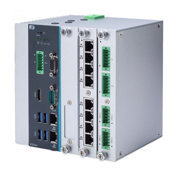
ICO500-518 Series User’s Manual CHAPTER 1 INTRODUCTION This chapter contains general information and detailed specifications of the ICO500-518. The Chapter 1 includes the following sections: General Description System Specification Dimensions I/O Outlets General Description The fanless embedded system ICO500-518 is an ideal solution for communications control and protocol converter applications in harsh environments. - Page 10 ICO500-518 Series User’s Manual Features Fanless design Wide temperature operation of -40℃ - +70℃ Supports 2 RJ-45 Gb Ethernet Supports dual display, 1 VGA and 1 HDMI 1 isolated COM Ports support RS-232/422/485 ...
-
Page 11: System Specifications
ICO500-518 Series User’s Manual System Specifications 1.2.1 ™ ™ ® Onboard Intel Core Celeron-3965U / Core i3-7100U processor (2.2GHz) processor ™ ™ (2.2GHz) / Core i5-7300U processor (2.6Hz) / Core i7-7600U processor (2.8GHz) 1.2.2 BIOS AMI (American Megatrends Inc.) UEFI (Unified Extensible Firmware Interface) BIOS. -
Page 12: Ethernet Ports
ICO500-518 Series User’s Manual 1.2.5 Ethernet Ports LAN Chip: Intel Ethernet Controller I210. The board has dual RJ-45 connectors, support 10/100/1000 Base-T with 1.5KV magnetic isolated protection. Pin Description 10/100Base-T 1000Base-T Transmit Data+ or Bidirectional BI_DA+ Transmit Data- or Bidirectional... -
Page 13: Wireless
ICO500-518 Series User’s Manual 1.2.7 Wireless 1 x Full size Mini Card slot supports module with USB and PCIe and SIM Interface (SLOT1). 1 x Full size Mini Card slot supports module with USB and PCIe Interface (SLOT2). -
Page 14: Usb
ICO500-518 Series User’s Manual 1.2.8 4 x USB3.0 Pin Signal Pin Signal USB_VCC SSRX2+ USB_Data2- USB_Data2+ 8 SSTX2- SSTX2+ SSRX2- 1.2.9 COM Port 1 DB9 ports support RS-232/422/485 which can be selected by BIOS. Supports Auto Flow Control in RS485 mode. -
Page 15: Power& Reset Button
ICO500-518 Series User’s Manual 1.2.12 Power& Reset Button AT auto power on Power button setting for software must be setted up firstly Pin Description Power Button Reset Button Note: Power button setting for Window is offered on APPENDIX B for reference 1.2.13... -
Page 16: System I/O Outlets
ICO500-518 Series User’s Manual 1.2.21 System I/O Outlets One HDMI connector display. One 15-pin D-Sub female connector for VGA. One 9-pin D-Sub male connector for COM. Two 10/100/1000 base-T RJ-45 with 1.5KV magnetic isolated protection. ... -
Page 17: Dimensions
ICO500-518 Series User’s Manual Dimensions The following diagrams show you dimensions and outlines of the ICO500-518. Introduction... -
Page 18: I/O Outlets
ICO500-518 Series User’s Manual I/O Outlets The following figures show you I/O outlets on front view and top view of the ICO500- 518. Introduction... -
Page 19: Chapter 2 Hardware Installation
ICO500-518 Series User’s Manual CHAPTER 2 HARDWARE INSTALLATION The ICO500-518 is flexible for your different hardware configurations, such as memory module, hard disk drive, mini card and I/O Module. The chapter 2 will show you how to install the hardware. - Page 20 ICO500-518 Series User’s Manual Step 4 Insert the PCIe Card into the slot and fasten screws. (Note: For the mini card with SIM function, the PCIe card should be inserted to the SLOT1) Step 5 Put the cover back to the system, and fasten all screws tightly to close the chassis.
-
Page 21: Installing The Hard Disk Drive, Cfast & Sim Card
ICO500-518 Series User’s Manual Installing the Hard Disk Drive, CFast & SIM Card Step 1 Turn off the system. Step 2 Loosing the screw as below, and drag out the HDD/SSD tray froom the system. Step 3 Loosing the screw as below left, and lock the screw to fix the SSD. Then lock the HDD/SSD back to the tray and install the tray back to the system. -
Page 22: Installing The Module Card
ICO500-518 Series User’s Manual Installing the Module Card Step 1 Turn off the system. Step 2 Loosen all screws of the cover and remove the cover from the system. Step 3 Installing the Module Card as below, and lock the screw to finish the installation. -
Page 23: Installing Din-Rail Mounting
ICO500-518 Series User’s Manual Installing Din-rail Mounting Step 1 Prepare Din-rail Mount assembling components (screws and bracket) ready. Step 2 Assembly the bracket to the system and fasten screws tight. Hardware Installation... - Page 24 ICO500-518 Series User’s Manual This page is intentionally left blank. Hardware Installation...
-
Page 25: Chapter 3 Ami Uefi Bios Utility
ICO500-518 Series User’s Manual CHAPTER 3 AMI UEFI BIOS UTILITY The AMI UEFI BIOS provides users with a built-in Setup program to modify basic system configuration. All configured parameters are stored in a flash-backed-up to save the Setup information whenever the power is turned off... -
Page 26: The Main Menu
ICO500-518 Series User’s Manual The Main Menu Once you enter the AMI BIOS Aptio Setup Utility, the Main Menu appears on the screen. In the Main Menu, there are several Setup functions and a couple of Exit options for your selection. Use Select Screen Keys (or Move Keys) to select the Setup Page you intend to configure then press <Enter>... -
Page 27: Advanced Features
ICO500-518 Series User’s Manual Advanced Features The Advanced menu also allows users to set configuration of the CPU and other system devices. Users can select any items in the left frame of the screen to go to sub menus: ►... - Page 28 ICO500-518 Series User’s Manual Hardware Monitor This screen displays the temperature of CPU and system, system voltages (+3.3V, +12V and +5V ,etc). AMI UEFI BIOS Utility...
- Page 29 ICO500-518 Series User’s Manual F81803 Super IO Configuration Use this screen to select options for the F81803 Super IO Configurations, and change the value of the selected option. A description of the selected item appears on the right side of the screen.
- Page 30 ICO500-518 Series User’s Manual Select Mode Use this option to set RS-232/RS-422/RS-485 mode. AMI UEFI BIOS Utility...
- Page 31 ICO500-518 Series User’s Manual CPU Configuration This screen shows the CPU version and its detailed information. AMI UEFI BIOS Utility...
- Page 32 ICO500-518 Series User’s Manual SATA Configuration SATA Mode Selection AHCI (Advanced Host Controller Interface) mode is how SATA controller(s) operate. Serial ATA Port 0~1 It shows the device installed in connector SATA0~1 AMI UEFI BIOS Utility...
- Page 33 ICO500-518 Series User’s Manual PCH-FW Configuration This screen shows ME Firmware information. AMI UEFI BIOS Utility...
- Page 34 ICO500-518 Series User’s Manual S5 RTC Wake Setting The default setting is on. If the setting is changed for setting is on. In the fixed time to boot up automatically. (Please refer below graphics.) AMI UEFI BIOS Utility...
- Page 35 ICO500-518 Series User’s Manual AMI UEFI BIOS Utility...
- Page 36 BIOS flash utility is a tool for flash BIOS on setup menu, follow the step to flash BIOS. zCreate a folder and rename to Axiomtek on the root of USB storage (Ex: X:\Axiomtek) Copy BIOS file to the Axiomtek folder (Ex: X:\Axiomtek\SBC87518X.005) (Note :...
- Page 37 ICO500-518 Series User’s Manual AMI UEFI BIOS Utility...
- Page 38 ICO500-518 Series User’s Manual AMI UEFI BIOS Utility...
- Page 39 ICO500-518 Series User’s Manual DeviceConfiguration Device configuration divide two part, one part is onboard device, the other is module device. Module device configuration menu would dynamic appear when module device is plug into slot, when no module plug in, it would only show onboard device configuration.
- Page 40 ICO500-518 Series User’s Manual Onboard DIO Configuration In the onboard DIO configuration, it displays DIO information and set I/O. (Please refer below graphics.) AMI UEFI BIOS Utility...
- Page 41 ICO500-518 Series User’s Manual AMI UEFI BIOS Utility...
- Page 42 ICO500-518 Series User’s Manual AMI UEFI BIOS Utility...
- Page 43 ICO500-518 Series User’s Manual AMI UEFI BIOS Utility...
- Page 44 ICO500-518 Series User’s Manual Module DIO Configuration When module has DIO function, the module DIO configuration menu would show, it display DIO information and set I/O. (Please refer below graphics.) AMI UEFI BIOS Utility...
- Page 45 ICO500-518 Series User’s Manual AMI UEFI BIOS Utility...
- Page 46 ICO500-518 Series User’s Manual Module COM port Configuration When module have COM port function, the module COM configuration menu would shown. The default setting for all Serial Ports are RS232. You can change the setting by selecting the value you want in each COM Port Type.
- Page 47 ICO500-518 Series User’s Manual AMI UEFI BIOS Utility...
-
Page 48: Chipset Feature
ICO500-518 Series User’s Manual Chipset Feature The Chipset menu allows users to change the advanced chipset settings. Users can select any of the items in the left frame of the screen to go to the sub menus: ► System Agent (SA) Configurations For items marked with “”, please press <Enter>... - Page 49 ICO500-518 Series User’s Manual Memory Configurations This screen shows the system memory information. AMI UEFI BIOS Utility...
-
Page 50: Security
ICO500-518 Series User’s Manual Security The default setting for Administrator Password is “Not setting passwords”. The Security menu allows users to change the security settings for the system. You can set the password for both Administrator Password and User Password. -
Page 51: Boot Type
ICO500-518 Series User’s Manual Boot Type The Boot menu allows users to change boot options of the system. Setup Prompt Timeout Use this item to set up number of seconds to wait for setup activation key where 65535(0xFFFF) means indefinite waiting. -
Page 52: Save & Exit
ICO500-518 Series User’s Manual Save & Exit The Save & Exit menu allows users to load system configurations with optimal or fail-safe default values. Save Changes and Exit When users have completed the system configuration changes, select this option to leave Setup and return to Main Menu. - Page 53 ICO500-518 Series User’s Manual Save Changes When completed the system configuration changes, select this option to save changes. Select Save Changes from the Save & Exit menu and press <Enter>. Select Yes to save changes. Discard Changes Select this option to quit Setup without making any permanent changes to the system configurations.
- Page 54 ICO500-518 Series User’s Manual This page is intentionally left blank. AMI UEFI BIOS Utility...
-
Page 55: Appendix Awatchdog Timer
ICO500-518 Series User’s Manual APPENDIX A WATCHDOG TIMER About Watchdog Timer After the system stops working for a while, it can be auto-reset by the watchdog timer. The integrated watchdog timer can be set up in the system reset mode by program. - Page 56 ICO500-518 Series User’s Manual This page is intentionally left blank. Watchdog Timer...
- Page 57 ICO500-518 Series User’s Manual APPENDIX B POWER BUTTON SETTING FOR WINDOWS Please make the power button setting from the console of PC, then follow up below pictures to do the setting. Power Button Setting For Windows...
- Page 58 ICO500-518 Series User’s Manual Power Button Setting For Windows...
- Page 59 ICO500-518 Series User’s Manual Power Button Setting For Windows...
Need help?
Do you have a question about the ICO500-518 Series and is the answer not in the manual?
Questions and answers