Table of Contents
Advertisement
Quick Links
Advertisement
Table of Contents

Related Manuals for THOMSON MEC 310#GENSET CONTROLLER


Summary of Contents for THOMSON MEC 310#GENSET CONTROLLER
- Page 1 MEC 310 GENSET CONTROLLER INSTALLATION AND OPERATION MANUAL r. 0472f PM075 Rev 2 09/08/20 9087A – 198 Street, Langley, BC Canada V1M 3B1 Telephone (604) 888-0110 Fax (604) 888-3381 E-Mail: info@thomsontechnology.com www.thomsontechnology.com...
- Page 2 This description of options covers the following products: MEC 310 SW version 1.2X.X...
-
Page 3: Table Of Contents
MEC 310 GENSET CONTROLLER Table of Contents ABOUT THIS DOCUMENT........................1 ............................1 ENERAL PURPOSE ............................1 NTENDED USERS .........................1 ONTENTS OVERALL STRUCTURE WARNINGS AND LEGAL INFORMATION ..................3 ....................3 EGAL INFORMATION AND RESPONSIBILITY ....................3 LECTROSTATIC DISCHARGE AWARENESS .............................3 AFETY ISSUES ............................3 ACTORY SETTINGS ..............................3 EFINITIONS GENERAL PRODUCT INFORMATION ..................5... - Page 4 .................................86 ETUP ..........................88 ARAMETER OVERVIEW ..............................90 AIL CLASS ) ....................91 NGINE ALARM SETTINGS PROTECTION ............................95 ULTI INPUTS ......................95 INARY INPUTS WITH WIRE BREAK 0(4)-20 A........................96 NALOGUE INPUTS ..............................98 INPUTS ..............................100 INPUT ........................107 MONITORING SETTINGS PM075 REV 2 09/08/20 THOMSON TECHNOLOGY...
-
Page 5: About This Document
The Installation Instructions and Reference Handbook is divided into chapters and in order to make the structure of the document simple and easy to use, each chapter will begin from the top of a new page. The following will outline the contents of each of the chapters. - Page 6 Parameter list This chapter includes a complete standard parameter list for setup. Therefore, this chapter is to be used for reference, when information about specific parameters is needed. PM075 REV 2 09/08/20...
-
Page 7: Warnings And Legal Information
Thomson Technology takes no responsibility for installation or operation of the generator set. If there is any doubt about how to install or operate the generator set controlled by the unit, the company responsible for the installation or the operation of the set must be contacted. - Page 8 MEC 310 GENSET CONTROLLER Warnings The warnings indicate a potentially dangerous situation which could result in death, personal injury or damaged equipment, if certain guidelines are not followed. PM075 REV 2 09/08/20 Page 4 THOMSON TECHNOLOGY...
-
Page 9: General Product Information
This chapter includes overall product information about the unit in general and its place in the Thomson Technology product range. Introduction The concept of the MEC 310 is to offer a simple and effective solution to gen-set builders, who need a flexible yet cost-competitive protection and control unit for small and medium-sized generators. -
Page 10: Options
The basic MEC 310 generator controller unit can be equipped with an AMF option needed to provide a real emergency power system controller. Furthermore, CANbus communication for different engine types is available and CANbus for up to two EAPs is possible at the same time. Also Modbus RS485 is available as an option. -
Page 11: Installation Instructions
The unit is designed for flush mounting by means of 4 fixing clamps (IP52), which are included at delivery. To have the IP65 (12 fixing clamps) the unit must be ordered with option L. The two fixing clamps on each side are mounted on the top and bottom of the MEC 310 box. - Page 12 MEC 310 GENSET CONTROLLER Terminal Description Must be installed in accordance with the NEC (United States) or the • CEC(Canada) Wire size: AWG 30 – 12 (or equivalent) • Use 60/75° C copper conductors only • Tightening torque: 5-7 lb-in (or equivalent) •...
- Page 13 If the uP fails or the power is lost, the relay will de-energize and the switch will open. If the unit fails to start up at power-up, then the relay switch will remain open. The binary output functions are configurable via the TPS 300 software and can be configured to...
- Page 14 Magnetic pick-up (2-wire) NPN or PNP pick-up* * These RPM inputs require external equipment. Tacho RPM input with capacitor (M/L) can be configured to cover the following functions: Magnetic pick-up (2-wire) W terminal on charger alternator NPN or PNP pick-up*...
-
Page 15: Wiring
Starter Start prep. Remote start Emer. STOP Start enable Status *: Term.12 can be used as alarm input if not used for charger generator terminal D+ Rex: 12V systems: 47 Ohm 4W Battery + 24V systems: 100 Ohm 6W Engine communication... -
Page 16: Binary Inputs
MEC 310 GENSET CONTROLLER If a stop coil is used, the REX resistor can be connected to the starter relay (crank). The illustrated configuration is the default factory setting. The use of the relays can be chosen freely. It is important to protect the unit against damage caused by high voltages. -
Page 17: Charger Alternator Connections
(excitation OK), the speed of the alternator will be above running speed, and the voltage on term. 12 will rise to a value higher than the battery voltage and then interrupt the current flow through REX and activate the running feedback input. Engine is running. -
Page 18: Connection Of The 3-Phase Voltage And Current
U L3 L1 s2 L1 s1 Generator L2 s2 current L2 s1 L3 s2 L3 s1 Generator Connection of the 1-phase 2-wire voltage and current MEC 310 Supply GB ON command GB OFF feedback U L1 Generator voltages Neutral L1 s2... -
Page 19: Connection Of The 2-Phase 3-Wire Voltage And Current
MEC 310 GENSET CONTROLLER Connection of the 2-phase 3-wire voltage and current PM075 REV 2 09/08/20 Page 15 THOMSON TECHNOLOGY... -
Page 20: Communication
Connect the cable shield to earth at one end only. GND terminal connection In case of communication problems, the GND terminals of the MEC 310 unit and the external device can be linked together using a third wire. CANbus Termination resistor The size of the terminating resistors should be 120 1%, 0.5W resistor. - Page 21 MEC 310 GENSET CONTROLLER For wiring details, please refer to ‘Wiring instructions’ in this section. In case of very long lines on the network, terminating resistors might be needed (typically 120 1%, 0.5W). The calculation should be based on the following data:...
- Page 22 MEC 310 GENSET CONTROLLER Option J, CANbus engine communication Connection with 2-wire shielded cable (recommended): MEC 310 Connection with 3-wire shielded cable: MEC 310 For wiring details, please refer to ‘Wiring instructions’ in this section. PM075 REV 2 09/08/20 Page 18 THOMSON TECHNOLOGY...
- Page 23 External I/O modules For wiring details, please refer to ‘Wiring instructions’ in this section. If External I/O modules is used together with EAP 300, the total terminal resistance of the EAP 300 and the External I/O controller must be 120...
- Page 24 EAP 300 and the External I/O controller must be 120 A DC/DC converter for the DC supply voltage and 2x1m cable with an RJ12 plug in one end and stripped wires in the other end is included in the EAP 300 delivery.
-
Page 25: Technical Information
50 Ω Wire break: I <2.5mA = Fault Response times: 500ms (From the set point is reached till the output is activated or the delay timer is started). Multi inputs: Resistor inputs, internal 3V supply Wire break: R >150 Ω... - Page 26 Resistive) 2 relays (MB & GB): 250V AC 30V DC 2A (UL/cUL Listed: Contact ratings 30V DC/30V AC 2A resistive) 2 relays (R24 & R26): 30V DC/AC 8A (UL/cUL Listed: 6A Resistive) 1 status relay: 24V DC 1A Resistive Mounting:...
- Page 27 MEC 310 GENSET CONTROLLER Unit dimensions and panel cutout PM075 REV 2 09/08/20 Page 23 THOMSON TECHNOLOGY...
-
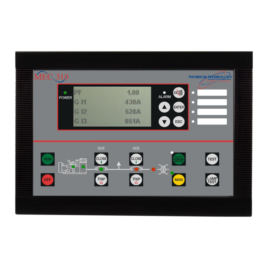
Page 28: Push-Buttons, Leds And Display
MEC 310 GENSET CONTROLLER 5. Push-buttons, LEDs and display This chapter deals with the display including the push-button and LED functions. Unit Front dimensions H x W 160 x 220 mm (6.30” x 8.66”) 54 mm (2.13 “) Unit depth... - Page 29 MEC 310 GENSET CONTROLLER RUN : Start engine (local (not auto)) running mode. OFF : Stops the engine instantaneously. If the unit is in AUTO mode, the mode will change to MANUAL and the engine will stop. TRIP : Trip the breaker.
- Page 30 Flashing (red): Active, non-acknowledged shutdown alarm(s) present. Steady (red): Active, acknowledged shutdown alarm(s) present. Flashing (amber): Active trip stop alarm, trip GB alarm or warning non-acknowledged alarm(s) present. Steady (amber): Active trip stop alarm, trip GB alarm or warning acknowledged alarm(s) present.
- Page 31 MEC 310 GENSET CONTROLLER Display functions The display indicates both readings and alarms. Illustrated below are examples with icons and English language. MEC 310 Type and software version. version Battery 24.0 V Battery voltage, RPM and running hours counter. 00000.h Service timer 1 and 2.
-
Page 32: Functional Descriptions
Alarms can be acknowledged in one of two ways: Either the binary input “alarm ack.” (selectable to be one of the binary inputs 10, 11, 12, 13, 14 and 15) is used, if this is configured for alarm acknowledge, or the select button on the display is used: The alarm acknowledge input acknowledges all present alarms, and the alarm LED will •... -
Page 33: Mains Voltage Unbalance Detection
(generator or option A mains breaker) will not be closed and the breaker’s LED will flash red. TPS 300 software input configuration It is possible to configure the inputs indicated in the table. The unit has a number of passive binary inputs (input terminals 10-15). Input function... - Page 34 GB position failure is displayed. 8. MB Pos on When this input is activated, the MEC 310 sees the mains breaker as open. If the MB on and the off feedback are on or off simultaneously, an MB position failure is displayed.
-
Page 35: Output Functions
(parameter 6212). 3. Prepare This function will close the relay as the first thing in the start sequence. The relay will be closed for the time programmed in parameter 6181. This function is used for preheating the engine or for prelubrication. - Page 36 MEC 310 GENSET CONTROLLER fail class. If 6130 is set to 0 seconds, it will be on until the reset horn push-button is activated or the alarm(s) has (have) been acknowledged. 8. Alarm/limit When this setting for the relay is selected, the relay can be used in the alarm parameters in the setting Output A and Output B.
- Page 37 LEDs. If the relay function is set as a limit relay, no warning pop-up will be shown in the display. The relay 0 is a virtual relay, so both output A and B must be set to limit relays if no warning in the display is wanted.
- Page 38 Run status timer has not yet expired. If the High Alarm is set, the alarm will be registered upon a closing contact. If the High Alarm is not set, the alarm will be registered upon an opening contact.
- Page 39 Common Alarm or Common Shutdown relay output you would need to perform the following steps: NOTE: For this example Relay 45 will be used as a Common Shutdown and Relay 47 will be used as a Common Alarm.
- Page 40 Remember to write the settings to the unit. 3. Under the M-Logic tab, the user will need to setup a Logic rung for Common Warning and a Logic rung for Common Shutdown. Have each Logic rung tied to the appropriate output relay.
- Page 41 MEC 310 GENSET CONTROLLER Setup a Logic rung with the following information for Relay 45 - Common Shutdown: From the dropdown list for From the dropdown list for Output- Select Relay 45 Event A - Select Shutdown NOT – •...
- Page 42 MEC 310 GENSET CONTROLLER 4. Under the Parameters tab of the TPS300 Software the user will need to setup all of the required Channels that will need to be associated to the Common Alarm or Common Shutdown relays. Example Parameter Settings: Setup parameter with required ‘Setpoints’...
-
Page 43: Alarm Inhibit
MEC 310 GENSET CONTROLLER Alarm inhibit In order to select when the alarms are to be active, a configurable inhibit setting for every alarm has been made. The inhibit functionality is only available via the PC utility software. For every alarm there is a drop-down window where it is possible to select which signals that have to be present in order to inhibit the alarm. - Page 44 Idle speed depends of the engine manufacture Shutdown override Inhibit if Shutdown override input is active If an alarm is configured to activate a limit relay, the relay will activate despite the fact that the inhibit input is ON. PM075 REV 2 09/08/20...
- Page 45 MEC 310 GENSET CONTROLLER Configuration of the External I/O External I/O’s have the same popup window with parameter settings as the internal I/O’s in MEC 310. PM075 REV 2 09/08/20 Page 41 THOMSON TECHNOLOGY...
- Page 46 MEC 310 GENSET CONTROLLER Programming of external I/O’s are done the same way as the inbuilt I/O’s in MEC 310. Using TPS 300 software. Only available external I/O’s are listed in Input/Output view. If e.g. one hardware module is removed, it will also be removed from the list above.
-
Page 47: Alarm Indication Leds
Alarm indication LEDs Alarm indication LEDs are the 4 LEDs placed in the right side of the front label on the MEC 310. In the clear window next to the LEDs a label can be placed to explain the function of the LEDs. No label is provided from the factory. -
Page 48: Parameter Groups
MEC 310 GENSET CONTROLLER Parameter groups Parameters shown in the display are split up in a default parameter list and the rest into three groups. It’s possible to select one or two of the groups or select them all. Language selection The unit has the possibility to display different languages. -
Page 49: Translation
MEC 310 GENSET CONTROLLER Translation Translation gives the customer the possibility to translate all texts that are shown in the display. Parameter texts used in the PC USW will only be shown in master language. Icons used for upload/download of translation. -
Page 50: Fail Class
MEC 310 GENSET CONTROLLER Fail class All the activated alarms of the MEC 310 must be configured with a fail class. The fail classes define the category of the alarms and the subsequent action of the alarm. Four different fail classes are available:... -
Page 51: Service Timers
The service timer alarm activates whenever the amount of days or the amount of running hours has expired. If the service timer is set to count down the display will shown 0 days or 0 hours; if the service timer is set to count up the display will show the amount of days or hours programmed in the parameter. -
Page 52: Counters
Counters for various values are included, and some of these can be adjusted if necessary, for instance if the unit is installed on an existing gen-set or a new circuit breaker has been installed. The table shows the adjustable values and their function in menu 6100: Description Function Comment. - Page 53 Hour setting Minute setting The digital input ‘auto start/stop’ cannot be used, when this function is enabled. It is necessary to use the TPS 300 software when setting up command timers (settings 10000 to 10310). PM075 REV 2 09/08/20 Page 49...
-
Page 54: Configurable Views In The Display
Configurable views in the display The views in the display are configurable; this gives the customer the opportunity to make their own views. There are up to 15 configurable views, which can all be set to 3 or 4 line views. Possible views... - Page 55 M L2-N XXX V M L3-N M L3-N XXX V M L1 L2 L3 Only in 4 line view M UL1 UL2 UL3 XXXX XXXX XXXX Vpn Only in 4 line view M UL12 UL23 UL32 XXXX XXXX XXXX Vpp...
- Page 56 MEC 310 GENSET CONTROLLER EIC P. Cool diff EIC P. Cool diff EIC P. Barometric EIC P. Barometric EIC T. Ambient Air EIC T. Ambient Air EIC T. Exh. Right EIC T. Exh. Right EIC T. Exh. Left EIC T. Exh. Left EIC T.
- Page 57 MEC 310 GENSET CONTROLLER 8-15 display views are empty PM075 REV 2 09/08/20 Page 53 THOMSON TECHNOLOGY...
-
Page 58: Vdo Sensors
VDO sensors are noise sensitive; therefore we recommend using 2 wire sensors. There are three VDO inputs in the unit. The inputs have different functions due to the fact that the hardware design is able to cover several VDO types. - Page 59 89.6 168.3 184.0 107.3 124.3 155.7 10.0 184.0 Type 4 is fully configurable with 8 points in the range 0-240 and 0-10.0 bar. The parameter settings can be found from menu 10810. PM075 REV 2 09/08/20 Page 55 THOMSON TECHNOLOGY...
- Page 60 70.1 113.2 19.8 51.2 83.2 15.8 38.5 62.4 11.7 29.1 47.6 22.4 28.9 18.2 Type 4 is fully configurable with 8 points in the range 0-2500 and 40-150° C or 104-302° F. PM075 REV 2 09/08/20 Page 56 THOMSON TECHNOLOGY...
- Page 61 8 settings are available from 0-150° or 104-302° F. VDO usage The VDO inputs are used as alarm inputs and can be configured in the following menus. VDO input 1: Fuel level - alarm settings in menus: 4230 VDO fuel level input 2.1 4240 VDO fuel level input 2.2...
-
Page 62: Binary Inputs With Cable Supervision
Switch open, cable OK 150 Ohm < R = Wire break The setting of the alarm input is carried out in the same way as the setting of the standard binary input. The texts can be changed in translation. PM075 REV 2 09/08/20... -
Page 63: Pm075 Rev
Fuel pump logic The fuel pump logic is used in order to start and stop the fuel supply pump to maintain the fuel level in the service tank at predefined levels. The start and stop limits are detected from the VDO 1 input. - Page 64 The fuel pump logic includes a fuel fill check function. When the fuel pump is running, the fuel level must increase with 4% within the fuel fill check timer. This timer is adjusted in 6550 Fuel pump logic, but the level of increase cannot be changed. If the fuel level does not increase at least 4% within the adjusted delay time, then the fuel pump relay will deactivate, and a fuel fill alarm occurs.
-
Page 65: Analogue Inputs 0(4)-20Ma
MEC 310 GENSET CONTROLLER Analogue inputs 0(4)-20mA The 0(4)-20mA setting can only be set in the TPS 300 software. 4-20mA inputs have wire break detection. The wire break detection limit is 2.5mA. Settings: Scale top point value (click the ‘...’). -
Page 66: Rpm Inputs
This schematic diagram shows the basic way the charger alternator and the MEC 310 can cooperate. Only one running feedback is needed, but for optimal safety and function both the RPM (Tacho) input and the digital running feedback (D+) can be used as in the example below. - Page 67 The 2-wire magnetic pick-up can be connected directly to terminals 17-18. NPN transistor output pick-up Since the NPN output is a frequency modulated DC pulse signal, a few external components are needed in order to eliminate the DC component. +12/24VDC...
-
Page 68: Generator Breaker Control
The generator breaker is assumed to be a contactor, i.e. the relay output is steady ON when the breaker is closed, and steady OFF when the breaker is open. It is not possible to have 2 pulse outputs for a motorised breaker (ON and OFF). -
Page 69: Test Function
MEC 310 GENSET CONTROLLER at all and hereby save fuel. If the engine has been running for a long period it will have reached normal running temperature, the cool-down period will be the exact time it takes to lower the temperature to be less than the temperature in set point 6213. - Page 70 7040. In this parameter it is also selected if this sequence should be started by a digital input and/or the test push-button on the front of the MEC 310. If the timer is set to 0, the test sequence will be interrupted when the digital input or test push-button is deactivated.
-
Page 71: M-Logic
M-logic is a simple tool based on logic events. One or more input conditions are defined, and at the activation of those inputs the defined output will occur. A great variety of inputs can be selected, such as digital inputs, alarm conditions and running conditions. -
Page 72: Buzzer
The MEC 310 has a built-in buzzer. The buzzer is configured in M-logic. This means that if the buzzer is going to be used as a horn annunciator, the input must be set to ‘Horn’ and the output must be set to ‘Buzzer’. The buzzer will act concurrently to the horn output timer. If the delay timer in M-logic is used, the buzzer will be active after this time delay. -
Page 73: Upgrade Of Firmware
MEC 310 GENSET CONTROLLER Upgrade of firmware 1. Connect PC to MEC 310 using Thomson Technology SSP interface 2. Open TPS 300 software(USW) and connect to MEC 310 3. Read parameters from MEC 310 using “Batch job” function PM075 REV 2 09/08/20... - Page 74 MEC 310 GENSET CONTROLLER 4. Select ALL parameters to be saved in USW project file. 5. Choose file name and where to save project file on PC PM075 REV 2 09/08/20 Page 70 THOMSON TECHNOLOGY...
- Page 75 New application software can be downloaded from www.thomsontechnology.com This will force MEC 310 into boot mode (LED 1 will flash red) If the programming should be interrupted, it’s possible to force the unit back into boot mode by disconnecting Aux. voltage. Press and hold the “OFF”...
- Page 76 MEC 310 GENSET CONTROLLER Indication of boot mode: blank display and LED 1 flash red. After download of new firmware is done, saved parameters can be downloaded into unit. 9. Open saved project file from PC 10. Write to device, using “Batch job” function...
- Page 77 MEC 310 GENSET CONTROLLER Select parameters which want to be downloaded into the unit. 12. Restart unit PM075 REV 2 09/08/20 Page 73 THOMSON TECHNOLOGY...
-
Page 78: Gsm Communication
The SIM card needed comes from your local mobile net provider. The easiest way to set the PIN code in the modem itself is to mount the SIM card in a mobile phone and change the PIN code there. The SIM card will remember the PIN code when it is installed in the modem. -
Page 79: Sms Alarms
MEC 310 GENSET CONTROLLER SMS alarms SIM card must support data transfer. Contact your GSM provider for details. 1. Setup GSM pin code 2. Setup of Alarm call numbers 3. Connect GSM modem to service port. 4. Disconnect Aux. supply to MEC 310. -
Page 80: Tps 300 Software Connection Via Modem
In the above example the modem is selected automatically by the TPS 300 software (internal modem in the PC). When you want to use modem dial-up, the TPS 300 software must also be set to run ASCII 7 bits data communication:... -
Page 81: Tps 300 Software Communication Safety
Use single setting downloads. TPS 300 software communication safety If the communication fails, the MEC 310 unit will operate according to the received data. If e.g. only half of the parameter file has been downloaded when the communication is interrupted, the settings are going to be a mix. -
Page 82: Auto Engine Start
MEC 310 GENSET CONTROLLER Auto engine start Start Auto Different mode R emote start input Mains fail The mains fail is an option Initiate star t sequence Engine running Start sequence ended Generator system Start fail f/U OK f/U timer... -
Page 83: Start Sequences
MEC 310 GENSET CONTROLLER Start sequences Start sequence Stop coil / normal prepare Start prepare Start output Stop output Start attempts Running feedback Start sequence Run coil / normal prepare Start prepare Start output Run coil Start attempts Running feedback... - Page 84 MEC 310 GENSET CONTROLLER Start sequence: Run coil / extended prepare Start prepare Start output Run coil Start attempts Running feedback Start sequence Stop coil / extended prepare Start prepare Start output Stop output Start attempts Running feedback PM075 REV 2 09/08/20...
- Page 85 MEC 310 GENSET CONTROLLER Start sequence Stop coil (not acc. in start seq.) / normal prepare / no stop between start attempts Start prepare Start output Stop output Start attempts Running feedback PM075 REV 2 09/08/20 Page 81 THOMSON TECHNOLOGY...
- Page 86 Start failure alarm – Auto only: Select Auto The start failure alarm will occur, if the engine has not started after the last start attempt. A start failure will activate the HORN output and relay outputs if selected. Start prepare...
- Page 87 If a binary input is not used, a timer function can be set to hold the engine in idle upon start until the timer runs out. This function can be selected to be: •...
-
Page 88: Stop Sequences
MEC 310 GENSET CONTROLLER Stop sequences The illustrations indicate the stop sequence schematically. Stop sequence / RUN coil Cool dow n time COOL Run coil Running feedback Stop sequence / STOP coil Cool dow n time Stop coil EX T... - Page 89 MEC 310 GENSET CONTROLLER Stop sequence The stop sequence will be activated, if a stop command is given. The stop sequence can include the cooling down time, if the stop is a normal or controlled stop. Description Cooling down Stop...
-
Page 90: Parameter List
MEC 310. To see the specific parameter, see in the parameter list. If e.g. a parameter is marked (P2), it is available from the display, if parameter group 2 is enabled. The default display parameter setting is the parameter setting that will always be present in the display parameter list. - Page 91 The third and fourth columns indicate the minimum/maximum set point available for this setting. The fifth column indicates the default set point of the unit from the factory. When it is necessary, additional information will be supplied after the table in order to make the individual parameter descriptions as informative as possible.
-
Page 92: Parameter Overview
6011…6015 Nominal settings 2 6552 Fuel pump 2: Setpoint* 6021…6025 Nominal settings 3 (1 ph) * Only shown if multi-input 1 is set to VDO 6031…6035 Nominal settings 4 (2ph) Always shown parameters in display 6041 Transformer U pri. Gen. - Page 93 Parameter table description The table consists of the following possible adjustments: Set point: The alarm set point is adjusted in the set point menu. The setting can be in percentage of the nominal values. PM075 REV 2 09/08/20 Page 89...
-
Page 94: Fail Class
Relay output B: A relay can be activated by output B. Enable: The alarm can be activated or deactivated. ON means always activated. Inhibits: It is possible to inhibit some of the alarms. This means it is only activated when the running feedback signal is present. Inhibit functions: Fail class: When the alarm occurs, the unit will react depending on the selected fail class. -
Page 95: Engine Alarm Settings (Protection)
Shutdown Trip 1030 Gen Overcurrent 1 Setting Min. setting Max. setting Third Factory setting setting 1031 Overcurrent 1 (P2) Set point 50.0% 200.0% 115.0% 1032 Overcurrent 1 (P2) Timer 0.1 s 3200.0 s 10.0 s 1033 Overcurrent 1 Relay output A... - Page 96 MEC 310 GENSET CONTROLLER 1170 Gen undervoltage Setting Min. setting Max. setting Third Factory setting setting 1171 Undervoltage (P2) Set point 50.0% 110.0% 90.0% 1172 Undervoltage (P2) Timer 0.1 s 100.0 s 5.0 s 1173 Undervoltage Relay output A R0 (none)
- Page 97 MEC 310 GENSET CONTROLLER 1250 Gen underfrequency 2 Setting Min. setting Max. setting Third Factory setting setting 1251 Underfrequency 2 (P2) Set point 50.0% 110.0% 85.0% 1252 Underfrequency 2 (P2) Timer 0.1 s 100.0 s 5.0 s 1253 Underfrequency 2...
- Page 98 L1L2L3 L1L3L2 L1L2L3 2282 Phase rotation Password Customer Service Customer The setting of Phase rotation depends of the wiring of Mains L1, L2 and L3. 2770 EIC control Setting Min. setting Max. setting Factory setting 2771 EIC Control Droop 0.0% 25.0%...
-
Page 99: Multi-Inputs
It is possible to combine VDO inputs with binary inputs and (0)4…20mA inputs in a mix. Binary inputs with wire break The text for the inputs for correct display reading can only be done via the TPS 300 software. 3400 Binary input 1 (fuel) Setting Min. -
Page 100: Analogue Inputs 0(4)-20Ma
MEC 310 GENSET CONTROLLER Analogue inputs 0(4)-20mA The scaling of the 0(4)-20mA inputs for correct display reading can only be done via the TPS 300 software. 4-20mA inputs have wire break function. Wire break alarm will be active when current goes below 2,5mA. It’s not possible to disable the wire break function. - Page 101 Output B R0 (none) R26 (relay 26) R0 (none) 4385 0(4)-20mA 3.1 Enable 4386 0(4)-20mA 3.1 Fail class See description of fail classes 4390 0-20 4-20mA 3.2 Setting Min. setting Max. setting Factory setting 4391 0(4)-20mA 3.2 Set point 20mA...
-
Page 102: Vdo Inputs
MEC 310 GENSET CONTROLLER VDO inputs 4220 VDO fuel level input 1.1 Setting Min. setting Max. setting Factory setting 4221 Fuel level 1.1 (P3) Set point 100% 4222 Fuel level 1.1 (P3) Delay 0.0 s 100.0 s 5.0 s 4223 Fuel level 1.1... - Page 103 R26 (relay 26) R0 (none) 4475 VDO 3.2 Enable 4476 VDO 3.2 Fail class See description of fail classes 4630 VDO low coolant temp. input 3.3 Setting Min. setting Max. setting Factory setting 4631 VDO 3.3 Set point -50° C 50°...
-
Page 104: Rpm Input
Relay output B R0 (none) R26 (relay 26) R0 (none) If the engine has not stopped within the delay time, outputs A and B will activate and a stop failure alarm occurs. PM075 REV 2 09/08/20 Page 100 THOMSON TECHNOLOGY... - Page 105 This alarm requires D+ input to be used in parallel with another running feedback at the same time (binary input, tacho, generator voltage). The status of both will be compared. If they do not match, a charger gen. alarm will be activated.
- Page 106 50X1 Relay X Function Alarm Limit Alarm 50X2 Relay X Off delay 0.0 s 999.9 s 5.0 s If option A is present, then parameter 5050 and 5060 are not available. PM075 REV 2 09/08/20 Page 102 THOMSON TECHNOLOGY...
- Page 107 When an alarm activates the relay, it is activated as long as the alarm is present and unacknowledged. If the Off delay is set different from 0.0 s, a short reset of the relay will take place when a new alarm appears.
- Page 108 Language Selectable* No 3 *See chapter page 40 regarding language selection The date and time can easily be synchronised with the laptop using the TPS 300 software or changed manual via display. PM075 REV 2 09/08/20 Page 104 THOMSON TECHNOLOGY...
- Page 109 According to factory setting the horn output will activate for 20 seconds when an alarm appears. If the timer setting is adjusted to 0, the horn relay will be activated continuously, until the reset alarm horn push-button is activated or the alarm is acknowledged.
- Page 110 1. When the time delay period expires, all the alarms which have Enable selected to ‘Not run status’ will be activated. 2. An output relay can be selected, if one is available. In that case, the settings output A and output B must be set according to the desired relay. To avoid an unwanted display alarm, ‘RUN STATUS ALARM’, the function of this relay must be selected to ‘Limit’...
-
Page 111: Hz/V Monitoring Settings
Idle mode can be controlled via a binary input. If this is selected, the idle mode remains for as long as the input is ON. If a binary input is not used, the idle mode can be selected to be active for manual or auto or both running modes. - Page 112 D+ input NO/NC If the D+ input is selected to be ON, this will be used as a running feedback. The D+ output from the charge generator must be connected to the input terminal configured to this function. The terminal 9 (common for terminals 10-15) must be connected to +, otherwise the D+ input does not work.
- Page 113 (e.g. display) are turned off. As soon as an event occurs (a button is activated, the input state changes), the sleep mode is ended.
- Page 114 Engine I/F Node CANopen ID 7563 Engine I/F EIC Controls 7564 Engine I/F EIC Auto View Menu 7562 is only used when MTU ADEC is selected as engine type. 7570 EIC comm. error Setting Min. setting Max. setting Factory setting 7571 EI comm.
- Page 115 Relay output B Not used Not used 7605 EIC overspeed Enable 7606 EIC overspeed Fail class Unit dependent Warning 7610 EIC coolant t. 1 Setting Min. setting Max. setting Factory setting 7611 EIC coolant t. 1 Set point -40 deg. 210 deg.
- Page 116 Warning 9110 Password Setting Min. setting Max. setting Factory setting 9116 Password Customer 9999 2000 9117 Password Service 9999 2001 User password If you forget the password, contact Thomson Technology for details. PM075 REV 2 09/08/20 Page 112 THOMSON TECHNOLOGY...
- Page 117 10371 GSM SMS telephone no. +9999999999999 +4511223344 10372 GSM Enable A telephone number set to 0 means not used. The prefix + and country code must always be entered. E.g. +1 for Canada. PM075 REV 2 09/08/20 Page 113 THOMSON TECHNOLOGY...
- Page 118 MEC 310 GENSET CONTROLLER 10460-10620 Fuel level config. sensor Setting Min. setting Max. setting Factory setting 10460 Fuel level type Type 10470 VDO 1 Fuel level Input 1 0 ohm 180 ohm 0 ohm 10480 VDO 1 Fuel level Output 1...
- Page 119 Set point Binary 10990 Conf inp 2 Set point Binary 11000 Conf inp 3 Set point Binary Possible selections: 4...20mA 0…20mA Binary Thomson Technology reserves the right to change any of the above. PM075 REV 2 09/08/20 Page 115 THOMSON TECHNOLOGY...
Need help?
Do you have a question about the MEC 310#GENSET CONTROLLER and is the answer not in the manual?
Questions and answers