Table of Contents
Advertisement
Quick Links
Advertisement
Table of Contents

Related Manuals for THOMSON TSC 900


Summary of Contents for THOMSON TSC 900
- Page 1 TSC 900 TRANSFER SWITCH CONTROLLER INSTALLATION, OPERATING & SERVICE MANUAL Part ID PM151 REV 5 16/04/19 9087A – 198 Street, Langley, BC Canada V1M 3B1 Telephone (604) 888-0110 Telefax (604) 888-3381 E-Mail: info@thomsonps.com www.thomsonps.com...
- Page 2 TSC 900 TRANSFER SWITCH CONTROLLER PM 151 REV 5 16/04/19 Thomson Power Systems...
-
Page 3: Table Of Contents
TSC 900 TRANSFER SWITCH CONTROLLER TABLE OF CONTENTS INTRODUCTION 1.1. PRODUCT REVISION HISTORY 1.2. GENERAL DESCRIPTION INSTALLATION 2.1. GENERAL INFORMATION 2.2. NOTES TO INSTALLER 2.3. TSC 900 GHC MOUNTING 2.4. AC VOLTAGE SENSING INPUT 2.5. AC CURRENT SENSING INPUT 2.6. - Page 4 TSC 900 TRANSFER SWITCH CONTROLLER 3.5. GHC DISPLAY MAIN MENU PAGE DESCRIPTIONS 3.5.1. HOME PAGE 3.5.2. UTILITY METERING PAGE 3.5.3. GENERATOR METERING PAGE 3.5.4. LOAD METERING PAGE 3.5.5. ALARMS PAGE 3.5.6. ALARMS LOG PAGE 3.5.7. EVENTS LOG PAGE 3.5.8. SYNC PAGE 3.5.9.
- Page 5 TSC 900 TRANSFER SWITCH CONTROLLER 4.9. TIMER BYPASS 4.10. MANUAL UTILITY RETRANSFER CONTROL 4.11. SERVICE DISCONNECT MODE 4.12. PHASE UNBALANCE PROTECTION ALARM RESET 4.13. TRANSFER HALTED ALARM RESET 4.14. ABNORMAL SOURCE ALERT PROGRAMMING INSTRUCTIONS 5.1. PASSWORD SECURITY DESCRIPTION (USERS ADMIN) 5.2.
- Page 6 TSC 900 TRANSFER SWITCH CONTROLLER 5.10.4. PHASE ROTATION REVERSED 5.10.5. RATED GENERATOR POWER 5.10.6. CT RATIO (CURRENT TRANSFORMER) 5.10.7. PT RATIO (POTENTIAL TRANSFORMER) 5.10.8. LOAD NAME 5.10.9. SOURCE 1 (UTILITY) NAME 5.10.10. SOURCE 2 (GEN) NAME 5.10.11. APPLICATION MODEL 5.10.12.
- Page 7 TSC 900 TRANSFER SWITCH CONTROLLER 5.12.4. GEN (SRC 2) WARM UP DELAY 5.12.5. TRANSFER NEUTRAL DELAY 5.12.6. TRANSFER PRE DELAY (LDC) 5.12.7. TRANSFER POST DELAY (LDC) 5.12.8. SRC 2 (GEN) GEN COMMIT TO TRANSFER DELAY 5.12.9. TRANSFER FAIL DELAY 5.12.10.
- Page 8 TSC 900 TRANSFER SWITCH CONTROLLER 5.14. LOAD VOLTAGE SET POINTS 5.14.1. LOAD VOLTAGE BLACKOUT DELAY (DROPOUT) 5.14.2. LOAD VOLTAGE BLACKOUT DROPOUT 5.14.3. LOAD VOLTAGE BLACKOUT PICKUP 5.15. LOAD SHED FREQUENCY & POWER SET POINTS 5.15.1. LOAD SHED INITIATE DELAY 5.15.2.
-
Page 9: Introduction
TS 870 Quick Start Manual, PM150 • TS 880 Instruction Manual, PM064 Contact Thomson Power Systems, to obtain these instruction manuals. A soft-copy of the most current versions of these manuals are available at www.thomsonps.com. PM 151 REV 5 16/04/19... -
Page 10: General Description
All features of the TSC 900 are fully programmable from the front panel color graphical touchscreen display and are security password protected. The graphical touchscreen display screen provides a user-friendly operator interface with many display options available. -
Page 11: General Information
Failure to confirm and match transfer switch voltage with the system voltage could cause serious equipment damage. If the transfer switch requires reconfiguring, the TSC 900 controller will also require reprogramming. CAUTION!!! Qualified personnel must complete all installation and/or service work performed only. -
Page 12: Tsc 900 Ghc Mounting
GHC is mounted on the ATS door with PEM studs as part of the door design. When the TSC 900 GHC is supplied loose for door mounting, it can be supplied with a door mounting faceplate with Lexan overlay (PART No’s 014222, 014221) which requires a rectangular door cut-out and mounting holes to be drilled as per the following drawings. -
Page 13: Ac Voltage Sensing Input
2.4. AC VOLTAGE SENSING INPUT The TSC 900 can accept direct AC voltage sensing inputs on the generator, utility and load from 120-600VAC (nominal). Sources up to 600VAC (phase to phase) can be connected wye or delta with grounded or ungrounded neutral without the need for additional sensing transformers. The... - Page 14 TSC 900 TRANSFER SWITCH CONTROLLER Voltage sensing connections for the most common applications are shown in the following diagrams. PM 151 REV 5 16/04/19 Thomson Power Systems...
-
Page 15: Ac Current Sensing Input
AC CURRENT SENSING INPUT The TSC 900 can accept 4 x 0-5Aac current inputs from the secondary windings of current transformers (CT’s). CT’s are to be connected on the load side of the ATS (Phase A, B, C & N). -
Page 16: Ac Control Power Input
, 10A (Resistive) powered output contact NOTE: Output voltage is dependent upon AC control power input voltage. Interposing relays are required between the TSC 900 outputs and the end device if loads exceed the output current rating. 2.10. EXTERNAL ATS CONTROL WIRING As a minimum, all external control wiring to/from the ATS must conform to the local regulatory authority having jurisdiction on electrical installations. -
Page 17: Remote Start Contact Field Wiring
DC power. It is strongly suggested that the ground return wire of the interposing relay be used for the interface to the TSC 900 remote start contact, this will ensure integrity of the DC power supply to the engine generator set controls in the event of a shorted or grounded wire remote start interface wire. -
Page 18: Communication Cable Installation
THOMSON POWER SYSTEMS factory. 2.13. DIELECTRIC TESTING Do not perform any high voltage dielectric testing on the transfer switch with the TSC 900 controller connected into the circuit, as serious damage will occur to the controller. All AC control fuses or control/sensing circuit isolation plugs connected to the TSC 900 must be removed/disconnected if high voltage dielectric testing is performed on the transfer switch. -
Page 19: Description
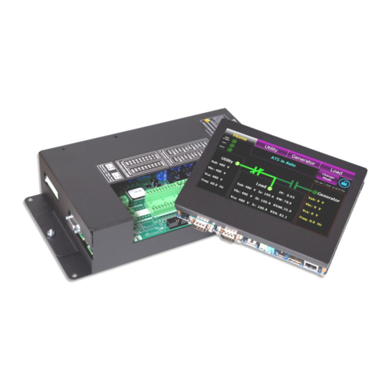
TSC 900 TRANSFER SWITCH CONTROLLER DESCRIPTION The TSC 900 controller consists of two parts; a front door mounted graphical touch screen display (GHC), and a switch control unit (SCU) which is mounted inside the transfer switch door. The two parts are interconnected via a USB 3.0A-to-micro-B high speed communication cable which includes DC... -
Page 20: Graphical Hmi Controller (Ghc) Display Hardware
1. RS232 Communication Port #1: This port is utilized for Modbus RTU Serial communication 2. RS232 Communication Port #2: This port is utilized RS232 Serial communication 3. USB Communication Port #1: This port is utilized for communication from GHC to TSC 900 SCU module. -
Page 21: Switch Control Unit (Scu) Hardware
TSC 900 TRANSFER SWITCH CONTROLLER 3.2. SWITCH CONTROL UNIT (SCU) HARDWARE The Switch Control Unit internal PCB is shown in the following diagram: PM 151 REV 5 16/04/19 Thomson Power Systems... - Page 22 TSC 900 TRANSFER SWITCH CONTROLLER The Switch Control Unit (SCU) with case and main I/O connections are detailed in the following diagram: 1. J9 – 24VDC Auxiliary Control Power 2. J2 – Utility Voltage Sensing (PH A, B, C, N) 3.
-
Page 23: Ats Operation Mode Descriptions
The TSC 900 requires continuous control power (i.e. utility/gen power on, or 24VDC aux power on) to keep the automatic engine start output disabled. If control power is de-energized, the engine start output will close in approximately 3 minutes, once its internal control power reservoir de-energizes. - Page 24 TSC 900 TRANSFER SWITCH CONTROLLER Operating modes for the ATS are selected either via the TSC 900 GHC Home page screen (using the “Change Mode” button) as shown on the screen images below or can be selected via external control switches as optionally connected to the TSC 900 Programmable inputs.
-
Page 25: Automatic Sequence Of Operation
3.4.2. CLOSED TRANSITION TRANSFER For transfer switches equipped with the closed transition transfer option (i.e. ATS Model Code Digit #13 “Operation Type” 3 or 4), the TSC 900 is configured to provide additional PM 151 REV 5 16/04/19 Thomson Power Systems... - Page 26 TSC 900 TRANSFER SWITCH CONTROLLER logic for this application. When the TSC 900 controller receives an input signal for Closed Transition Transfer Mode, the TSC 900 is configured to operate as follows: Under normal closed transition operating conditions, the transfer switch operates automatically during a failure and restoration of utility power and does not require operator intervention.
-
Page 27: Dual Source Ats
TSC 900 TRANSFER SWITCH CONTROLLER 3.4.3. DUAL SOURCE ATS ATS may be supplied with the following 3 types of optional Dual Source system configurations: • DU - Dual Utility ATS: Used for systems consisting of one ATS connected to two utilities with at least one source continually energized to the ATS. - Page 28 TSC 900 TRANSFER SWITCH CONTROLLER remain off load. The standby source will automatically transfer on load should the “Preferred” source fail once the “ Transfer From Preferred Source Delay” timer expires . When the “Preferred” selected source is returned to normal operating status, the load will automatically retransfer back to the “Preferred”...
- Page 29 TSC 900 TRANSFER SWITCH CONTROLLER 3.4.3.3. DUAL STANDBY GENERATOR ATS Under normal Utility Power operation, power to the load will be fed from the Master ATS via closed Utility power switching device. The Dual Standby (“Slave”) ATS remains de-energized with both generators stopped. Should the utility power fail, the Master ATS will send a common gen start signal to the Dual Standby ATS.
-
Page 30: Automatic Load Shed Operation
TSC 900 TRANSFER SWITCH CONTROLLER 3.4.4. AUTOMATIC LOAD SHED OPERATION The TSC 900 can be configured for automatic Load Shedding operation by use of a programmable output contact. Under normal utility power conditions, the Load Shed control is not activated. When a utility power failure occurs and the ATS transfers to the generator supply, the Load Shed circuit is automatically initiated for a pre-programmed time delay setting. -
Page 31: Test Mode
TSC 900 TRANSFER SWITCH CONTROLLER 3.4.5. TEST MODE 3.4.5.1. ON LOAD TEST (OPEN TRANSITION TRANSFER) When an operator selects an ON LOAD TEST mode, the ATS controller will initiate a simulated utility power failure condition. The transfer switch will operate as per a normal utility power fail condition with all normal time delays enabled. -
Page 32: Abnormal Sequence Of Operation
Note: the TSC 900 programmable digital input for Service Disconnect mode must be used in conjunction with a Service Disconnect control switch which changes the source of control power to the TSC 900 output contacts to enable transfer to the neutral position. -
Page 33: Ghc Display Main Menu
3.5. GHC DISPLAY MAIN MENU PAGE DESCRIPTIONS The GHC software provides the TSC 900 control and monitoring information which is visible on the GHC Display or remote PC. All screen page navigation is controlled by a touchscreen display using a “finger swipe” motion and/or button press actions. The GHC has pre-programmed display pages which are selected manually using the touchscreen display. -
Page 34: Home Page
TSC 900 TRANSFER SWITCH CONTROLLER 3.5.1. HOME PAGE The Home Page is utilized as a summary control and monitoring screen for the ATS. This screen provides a mimic bus showing current ATS position, identifies which sources are energized, voltage levels and overall ATS operating mode. Phase to phase system voltages will be displayed for each source and load. -
Page 35: Utility Metering Page
TSC 900 TRANSFER SWITCH CONTROLLER 3.5.2. UTILITY METERING PAGE The utility metering page provides detailed voltage and frequency metering data for the utility supply. Metering data is displayed in both text and graphical representation. Phase to phase and phase to neutral voltages are displayed as well as a Phasor diagram showing relative phase angles and magnitudes between phases. -
Page 36: Load Metering Page
3.5.5. ALARMS PAGE The TSC 900 alarms page displays available alarms based on the model type of ATS supplied. Any active alarms will be highlighted with Red background fill. A reset button is provided on this page to reset all activated alarms. The following is a screen shot for a standard open transition ATS. -
Page 37: Alarms Log Page
5.12.9. TAG: alm.xfr.mech.2 Load on Src 1 Limit Sw/Aux Contact Alarm is activated if the “Load On Utility” (Src 1) input signal to the TSC 900 is lost during normal Failure operation, while the Utility is supplying the load. TAG: alm.xfr.detect.1 Load on Src 2 Limit Sw/Aux Contact Alarm is activated if the “Load On Generator”... - Page 38 TSC 900 TRANSFER SWITCH CONTROLLER When the Calendar pop-up is selected, any calendar dates with alarm logs present will be highlighted by a “red” box on that date as per the following display. PM 151 REV 5 16/04/19 Thomson Power Systems...
-
Page 39: Events Log Page
TSC 900 TRANSFER SWITCH CONTROLLER 3.5.7. EVENTS LOG PAGE The events log page shows time/date stamped information as to when events have occurred. A drop down menu is provided to select a desired filter to view the logs. Note: A calendar date must be selected for the desired date to determine if any logs are visible on that date. -
Page 40: Sync Page
TSC 900 TRANSFER SWITCH CONTROLLER 3.5.8. SYNC PAGE The SYNC page is utilized for applications when the ATS is provided with closed transition or open transition in-sync transfer capability. This page will display the phase angle difference, voltage difference and slip frequency difference between two available sources. -
Page 41: Scheduler Page
TSC 900 TRANSFER SWITCH CONTROLLER 3.5.9. SCHEDULER PAGE The scheduler page is utilized to set on load or off-load Exercise events using a calendar based scheduler. Multiple exercise events, dates and times can be selected. By pressing the “New” or “Edit” buttons a pop-up menu will appear as shown below. Refer to Operating Instruction section of this manual for further details on how to configure the Exercise Scheduler. -
Page 42: System Page
TSC 900 TRANSFER SWITCH CONTROLLER 3.5.10 SYSTEM PAGE The System Page is utilized for viewing or programming specific settings based on the application. Each System sub-menu page can be viewed by selecting the specific button. Refer to Section 3.6 for description of each submenu. -
Page 43: Ghc Display System Submenu
GHC SD memory card. Refer to the Programming section of this manual for further details on import/back-up operating procedures. 3.6.2. DATE / TIME SETUP The date/time setup page is utilized for changing the TSC 900 real time clock settings to match the installed location. Refer to the Section 5.4... -
Page 44: Manage Users
Refer to the Programming section of this manual for further details on editing or adding new users. 3.6.4. SYSTEM INFORMATION The System page shows what current firmware versions are installed on the TSC 900 controller. PM 151 REV 5 16/04/19... -
Page 45: Input Mapping
TSC 900 TRANSFER SWITCH CONTROLLER 3.6.5. INPUT MAPPING The input mapping page shows what functions the TSC 900 programmable digital inputs are configured for and which inputs are currently activated. Refer to the Section 5.8 of this manual for further details on configuring the digital input mappings. -
Page 46: Logs
The logs page shows the available data logs the controller is logging on a real-time basis. 3.6.8. COMMUNICATION STATUS The communication status page shows status of all TSC 900 controller communication ports including Serial (RS232) port, Ethernet (TCP/RTU) ports and the SCU-GHC USB ports. Specific com port settings and operating statistics can be accessed via this screen. -
Page 47: Mimic Bus Customization
3.6.10. FIRMWARE UPDATES The firmware updates page allows the user to update new firmware in the GHC display and/or the SCU controller. Contact Thomson Power Systems for applicable Service Bulletin which details the GHC and SCU firmware update procedure. 3.6.11. GHC HEALTH The GHC health page provides diagnostic information for the GHC with regards to memory utilization. -
Page 48: Operating Instructions
TSC 900 TRANSFER SWITCH CONTROLLER OPERATING INSTRUCTIONS The GHC software provides the TSC 900 control and monitoring information which is visible on the GHC Display or remote PC. All screen page navigation is controlled by a touchscreen display using a “finger swipe”... -
Page 49: On Load Test Instructions (Utility Power Fail Simulation)
TSC 900 TRANSFER SWITCH CONTROLLER 4.3. ON LOAD TEST INSTRUCTIONS (UTILITY POWER FAIL SIMULATION) To perform an On Load Test and simulate a utility power fail condition, press the “Change Mode” control button on the GHC Home Page and select “ON LOAD TEST” mode from the available list of modes as shown below. -
Page 50: Off Load Test Instructions (Generator No Load Test)
TSC 900 TRANSFER SWITCH CONTROLLER To cancel On Load Test, press the “Change Mode” control button on the GHC Home Page and select “RETURN TO AUTO” mode from the available list of modes as shown below. The “Test” and “Engine Start” lights on the upper left-hand corner of the screen will go off and the load will re-transfer back to the utility power per Automatic Sequence. -
Page 51: Timed Test Instruction
TSC 900 TRANSFER SWITCH CONTROLLER To cancel the “Off load” Test, press the “Change Mode” control button on the GHC Home Page and select “RETURN TO AUTO” mode from the available list of modes as shown below. The “Engine Start” light on the upper left-hand corner of the screen will go off and the generator set will stop. - Page 52 TSC 900 TRANSFER SWITCH CONTROLLER To cancel TIMED TEST mode, press the “Change Mode” control button on the GHC Home Page and select “CANCEL TIMED TEST” mode from the available list of modes as shown below. PM 151 REV 5 16/04/19...
-
Page 53: Open/Closed Transition Transfer Operation
TSC 900 TRANSFER SWITCH CONTROLLER 4.6. OPEN/CLOSED TRANSITION TRANSFER OPERATION The ATS may be supplied with a number of different Open or Closed Transition Transfer operational features. The ATS model code depicts the options available as shown below: Operational behavior of an ATS equipped with these different features is depicted in the... -
Page 54: Open Transition In-Sync Transfer Operation (Model X)
TSC 900 TRANSFER SWITCH CONTROLLER 4.6.1. OPEN TRANSITION IN-SYNC TRANSFER OPERATION (MODEL X) If the ATS is supplied with ATS Model X feature (i.e. Open Transition – In-sync Transfer), the ATS will operate as per automatic sequence of operation (open transition) however all transfers will occur using in-sync transfer control sensing instead of neutral delay control logic. -
Page 55: Closed Transition Operation (Soft-Load Transfer Model 4)
TSC 900 TRANSFER SWITCH CONTROLLER The right-hand side of the display shows the status of the Closed Transition Transfer “Permit” or Inhibit” signals. Depending on the operating status of the ATS, Closed Transition Transfer will be inhibited should only 1 source of supply be available or Protection Lock-out relay has been activated. - Page 56 TSC 900 TRANSFER SWITCH CONTROLLER The left-hand side of the display shows the current position of the ATS control modes. Model 4 ATS provides 3 different operating mode via GHC Display button or external control switches as follows: 4.6.3.1. TRANSFER MODE SELECTION Transfer mode selection may be done via internal GHC display buttons, or external control switch.
- Page 57 TSC 900 TRANSFER SWITCH CONTROLLER • DISABLE: The Soft-Load operating mode is disabled in this mode. The ATS will operate in either Open or Closed Transition Fast Transition as selected. • ENABLE: The ATS will operate in a Soft-Load Closed Transition transfer sequence if both sources are available.
-
Page 58: Dual Source Ats Operation
3. Preferred Source Indication: When a source is selected as the “Preferred source”, it will be indicated via text as indicated above. Preferred source selection maybe via External control switch or TSC 900 GHC display. PM 151 REV 5 16/04/19... -
Page 59: Dual Source - Changing Preferred Units (Ghc Control)
TSC 900 TRANSFER SWITCH CONTROLLER 4.7.1. DUAL SOURCE - CHANGING PREFERRED UNITS (GHC CONTROL) To change the “Preferred Source” on an ATS using the GHC screen source selection, press the “Change Mode” control button on the GHC Home Page and select “CHANGE PREFER SOURCE”... -
Page 60: Transfer Fail Alarm Reset
“RESET ALARMS” button. 4.9. TIMER BYPASS The following automatic sequencing time delays can be temporarily bypassed when the time function is active as shown on the TSC 900 GHC display: • Utility Return Timer • Cooldown Timer •... -
Page 61: Manual Utility Retransfer Control
TSC 900 TRANSFER SWITCH CONTROLLER 4.10. MANUAL UTILITY RETRANSFER CONTROL If the TSC 900 is pre-programmed to provide a Manual return to the utility supply following a utility power failure, an operator can decide when to initiate the re-transfer sequence by pressing the “MANUAL RETURN”... -
Page 62: Phase Unbalance Protection Alarm Reset
TSC 900 TRANSFER SWITCH CONTROLLER 4.12. PHASE UNBALANCE PROTECTION ALARM RESET When the TSC 900 is programmed with Phase Unbalance protection enabled, should a transfer occur due to an out of limit phase unbalance condition, an alarm message will be shown on the TSC 900 GHC display “UTILITY (or GEN) UNBALANCED”. -
Page 63: Transfer Halted Alarm Reset
TSC 900 TRANSFER SWITCH CONTROLLER 4.13. TRANSFER HALTED ALARM RESET Should a transfer switch failure occur during a transfer to a new intended source, a “TRANSFER HALTED” alarm will be posted to the GHC home screen as shown below. The transfer switch will remain in this current position until the Transfer Halted condition is manually reset by ATS operator utilizing the RELEASE TRANSFER reset button on the GHC home page. -
Page 64: Abnormal Source Alert
TSC 900 TRANSFER SWITCH CONTROLLER 4.14. ABNORMAL SOURCE ALERT Should an abnormal source condition be detected by the TSC 900, a red Source Alert triangle Icon will automatically start flashing on the home screen as shown below. To view which specific condition has triggered the alert, press the alert Icon and a pop-up screen will be displayed as shown below. -
Page 65: Programming Instructions
TSC 900 TRANSFER SWITCH CONTROLLER PROGRAMMING INSTRUCTIONS 5.1. PASSWORD SECURITY DESCRIPTION (USERS ADMIN) To prevent un-authorized access, users are required to “Login” in order to: • Acknowledge and reset alarms • Change operating modes • Change Configuration settings • Manage Users •... -
Page 66: User Login Procedure
TSC 900 TRANSFER SWITCH CONTROLLER 5.2. USER LOGIN PROCEDURE With the transfer switch energized, follow the procedure below to Login to the TSC 900 controller: • Navigate to the “Home” Page below and select the Locked Icon as shown below •... -
Page 67: Administrator Password Management Procedure
TSC 900 TRANSFER SWITCH CONTROLLER 5.3. ADMINISTRATOR PASSWORD MANAGEMENT PROCEDURE With the transfer switch energized, follow the procedure below to add or edit a list of ATS users. • Navigate to the “System” Page and select “Manage Users” as shown below •... -
Page 68: System Time/Date Adjustment
TSC 900 TRANSFER SWITCH CONTROLLER 5.4. SYSTEM TIME/DATE ADJUSTMENT To adjust the TSC 900 controller’s internal time clock, follow the detailed procedure below. • Navigate to SYSTEM screen and press TIME/DATE SETUP button as shown below. • Select Date field and a calendar will automatically pop-up to allow selection of day, month and year as shown below. -
Page 69: Voltage Change Procedure
All voltage changes are done via software programming only. • Login to the TSC 900 with a level of “POWER” or “ADMIN” as described in Section 5.2. Note: Initial Factory Default Password is “pass” •... - Page 70 TSC 900 TRANSFER SWITCH CONTROLLER • On the System Voltage Row, select the type of system configuration (i.e. wye or delta) per voltage diagrams provided, then select the applicable voltage from the drop down list as shown below. If the desired voltage is not listed, select “Custom” and enter the Line to Line System voltage.
-
Page 71: Remote Communication Setup
(i.e. On Load or Off Load). The exercise timer utilizes the TSC 900 GHC internal real-time clock for referencing all timing functions. The GHC real-time clock utilizes a battery back-up power source to retain correct time/date settings during short duration utility power failures. -
Page 72: Editing Existing Exercise Schedule Event
TSC 900 TRANSFER SWITCH CONTROLLER • Once in the Scheduler Editor page, select desired Exercise type (on load or off load), then select desired Exercise schedule (i.e. period, reoccurrence, start time, stop time, end date, end time and exercise duration). -
Page 73: Programmable Digital Input Mapping
In addition, programmable inputs may be programmed with custom names to suit a specific application. The TSC 900 is provided with factory programmed default settings based upon the ATS configuration. Refer to the following sections for specific default program tables. -
Page 74: Ts 880 (Ics) Standard/Service Entrance Input Defaults
TSC 900 TRANSFER SWITCH CONTROLLER 5.8.3. TS 880 (ICS) STANDARD/SERVICE ENTRANCE INPUT DEFAULTS: Inputs GHC Descriptions SCU TAG Names Remote Test - Utility Power Fail Simulate IP01 test.req.remote.a Remote Alarm Reset IP02 ctl.reset.req Service Disconnect Mode Activated IP03 ctl.discon.req.a Utility Power Switching Device (USD) Tripped IP04 tip.switch.tripped.1... -
Page 75: Programmable Input Function List
TSC 900 TRANSFER SWITCH CONTROLLER 5.8.5. PROGRAMMABLE INPUT FUNCTION LIST The following input functions can be mapped to any programmable input. Note: inputs can be programmed only once (i.e. same input type cannot be utilized on multiple programmable inputs). TagName TagDescription ctl.discon.req.a... - Page 76 TSC 900 TRANSFER SWITCH CONTROLLER TagName TagDescription ilk.xfr.closed.inhibit Closed Transition Mode Inhibit ilk.xfr.closed.inhibit.prot Closed Transition Inhibit Prot ilk.xfr.closed.permit Closed Transition Mode Permit ilk.xfr.inphase.inhibit In-Phase Transfer Inhibit ilk.xfr.inphase.permit In-Phase Transfer Permit ilk.xfr.ndtbypass.inhibit NDT Bypass Inhibit ilk.xfr.ndtbypass.permit NDT Bypass Permit ilk.xfr.parallel.inhibit Enable Extended Parallel Transfer Inhibit (CTTS Model 4) ilk.xfr.parallel.permit...
-
Page 77: Programmable Input Function Mapping
TSC 900 TRANSFER SWITCH CONTROLLER 5.8.6. PROGRAMMABLE INPUT FUNCTION MAPPING To edit programmable inputs, follow the procedure listed below: a) From the GHC Home Page, navigate to the “SYSTEM” Page and select “Input Mapping” as shown below: b) With the Input Mapping page displayed, press the EDIT button as shown below:... -
Page 78: Programmable Input User Defined Custom Name Mapping
TSC 900 TRANSFER SWITCH CONTROLLER e) To return to the input mapping page once the change is accepted, press red X icon on the screen. 5.8.7. PROGRAMMABLE INPUT USER DEFINED CUSTOM NAME MAPPING Up to 16 Programmable inputs may be programmed with custom names to suit specific applications (e.g. - Page 79 Once the custom name is entered, you can select if the programmable input is to be included or excluded from the TSC 900 alarms feature. Select the required check box as shown. Once complete, press the “Confirm” but to complete the entry.
-
Page 80: Programmable Output Mapping
All 8 Programmable outputs can be mapped to a number of different parameters to suit the application. The TSC 900 is provided with factory programmed default settings based upon the ATS configuration. Refer to the following sections for specific default program tables. -
Page 81: Programmable Output Function List
TSC 900 TRANSFER SWITCH CONTROLLER 5.9.5. PROGRAMMABLE OUTPUT FUNCTION LIST The following output functions can be mapped to any programmable output. Note: outputs can be programmed multiple times to provide additional output contacts of same type. TagName TagDescription alm.any ATS Common Fail Alarm alm.gen.failtorun.1... - Page 82 TSC 900 TRANSFER SWITCH CONTROLLER TagName TagDescription ctl.outputs.o03 User Def Output 3 ctl.outputs.o04 User Def Output 4 ctl.outputs.o05 User Def Output 5 ctl.outputs.o06 User Def Output 6 ctl.outputs.o07 User Def Output 7 ctl.outputs.o08 User Def Output 8 ctl.reset.req Reset Alarm Request ctl.rtn.req.a...
- Page 83 TSC 900 TRANSFER SWITCH CONTROLLER TagName TagDescription ilk.xfr.tosrc.1.permit Permit Transfer to SRC 1 ilk.xfr.tosrc.2.permit Permit Transfer to SRC 2 sync.xfr.trigger Sources are In-Phase test.active Test Active test.active.local Local Test Active test.active.remote Remote Test Active test.req.remote.a Remote Test Request test.req.remote.b GHC Test Request tip.switch.onsrc.1...
-
Page 84: Programmable Output Function Mapping
TSC 900 TRANSFER SWITCH CONTROLLER 5.9.6. PROGRAMMABLE OUTPUT FUNCTION MAPPING The edit the programmable outputs, follow the procedure listed below: a) From the GHC Home Page, navigate to the “SYSTEM” Page and select Output Mapping as shown below b) With the Output Mapping page displayed, press the EDIT button as shown below:... -
Page 85: System Settings
Section 6 Factory Default Programming. The TSC 900 controller provides a flexible control system to allow specific operation for a wide range of applications. To program settings, navigate to the “Settings” page as shown below. Once on the Settings Page, select the group of Settings by adjusting the filter and scroll through available list of functions as available. -
Page 86: System Phases
Refer to Section 2.4 for a listing of available AC system voltage sensing configurations possible with a TSC 900. 5.10.3. SYSTEM FREQUENCY Set to nominal system frequency of either 50Hz or 60Hz. -
Page 87: Load Name
Mechanism Type S, T or ICS). This is a “read-only” parameter and cannot be changed. 5.11. OPTION SETTINGS The TSC 900 has a number of options which can be set depending on type. To program Options, navigate to the “Settings” page. Once on the Settings Page, select the “OPTIONS” on the left side menu bar, and scroll through available list of functions as available. -
Page 88: Enable Load Shed On Under Frequency
5.11.4.1. MANUAL SRC 1 (UTILITY) RETRANSFER CONTROL The TSC 900 transfer switch controller contains a “MANUAL SRC 1 (UTILITY) RETRANSFER CONTROL” feature, which allows an operator initiated re-transfer sequence to occur when utility power has returned following a power failure. This feature... -
Page 89: Force Transfer
TSC 900 controller, a Transfer Switch Fail Alarm will be posted on the GHC display. The TSC 900 controller will keep the ATS mechanism in the current position and will take no further action. -
Page 90: Modbus Tcp/Ip
When the security bypass feature is enabled, it allows the ATS to be operated without a security login. The TSC 900 is supplied from the factory with this feature enabled to allow initial ATS operation during commissioning without the need for a security login. It is recommended to disable this feature once the ATS is turned over to the end user so that desired security passwords can be used. -
Page 91: Enable Transfers To Src 2 (Generator)
ENABLE HALT TRANSFER ON FAIL TO EXTERNAL SYNC CHECK The TSC 900 transfer switch controller contains a “HALT TRANSFER ON FAIL TO EXTERNAL SYNC CHECK” logic selection feature. This feature is user programmable and controls how the external automatic synchronizer initiate output is controlled. -
Page 92: Revert To Open Transition
Digit #13 “Operation Type” 4), a fail to unload alarm feature is available. When feature is set to “Yes”, the TSC 900 controller will monitor the status of programmable inputs configured for Utility unloaded (DI-12) and Generator unloaded (DI-13). When enabled,... -
Page 93: Enable Extended Parallel Mode (Ctts Model 4)
TSC 900 TRANSFER SWITCH CONTROLLER 5.11.19. ENABLE EXTENDED PARALLEL MODE (CTTS MODEL 4) When the ATS is ordered with a Closed Transition soft-load option (i.e. ATS Model Code Digit #13 “Operation Type” 4), the ATS can be operated in Extended Parallel mode. -
Page 94: Preferred Source Alternation Interval
TSC 900 TRANSFER SWITCH CONTROLLER 5.11.22. PREFERRED SOURCE ALTERNATION INTERVAL When the ATS is ordered with a Dual Source option, a control feature is provided to allow automatic changing of “Preferred” sources to balance operating hours. The feature allows a programmable time interval between 1 - 672 hours. Note: This control feature is only operational when the “Preferred”... -
Page 95: Delay Settings
TSC 900 TRANSFER SWITCH CONTROLLER 5.12. DELAY SETTINGS The TSC 900 provides the following programmable time delay features: 5.12.1. UTILITY (SRC 1) RETURN DELAY The utility return delay period will be initiated once the utility supply has returned within limits following a utility power failure condition. Select desired utility return delay time in seconds. -
Page 96: Transfer Neutral Delay
5.12.10. TRANSFER MAX ERROR CONDITION DELAY The TSC 900 controller continuously monitors the status of ATS mechanism position inputs (i.e. on source 1 and on source 2). If an abnormal condition is detected, the Transfer Max Error Condition Delay timer is activated. -
Page 97: Gen (Src 2) Failed To Start Delay
When a power switching device fails to trip open for any reason, the TSC 900 will attempt to re-open it by providing an on/off pulse signal. The duration of the on/off pulse signal is set by the Trip Retry On/Off Pulse Time setting. -
Page 98: Close Retry Duration Timer (Src1&2)
When a power switching device fails to close for any reason, the TSC 900 will attempt to re-close it by providing an on/off pulse signal. If a retry is unsuccessful, the TSC 900 will continue retrying until expiry of the Trip Retry Duration Timer. -
Page 99: Return To Preferred Source Delay
If no delay is required, set this time delay to zero. 5.13. UTILITY/GEN SET POINTS (VOLTAGE/FREQUENCY) The TSC 900 controller provides 3-phase over voltage and under voltage sensing on both utility and generator supplies. Each sensor is individually programmable for pickup and dropout voltage set points (i.e. -
Page 100: Under Voltage Delay (Dropout)
TSC 900 TRANSFER SWITCH CONTROLLER supplies. Each sensor is individually programmable for pickup and dropout frequency set points (i.e. adjustable hysteresis) in addition to transient time delay settings. To program the voltage and frequency sensing features, refer to the following descriptions: Note: each of the following set points are programmable for each source (e.g. -
Page 101: Phase Unbalance Delay (Pickup)
TSC 900 TRANSFER SWITCH CONTROLLER NO (DISABLED): The controller will automatically initiate a retransfer sequence once the original sources phase unbalance condition returns within nominal limits as programmed. YES (ENABLED): The controller will not automatically initiate a retransfer sequence following a phase unbalance alarm condition but the alarm will latch in. To initiate... -
Page 102: Under Frequency Pickup
TSC 900 TRANSFER SWITCH CONTROLLER 5.13.13. UNDER FREQUENCY PICKUP Set to the desired source under frequency pick-up set point as expressed in percentage of nominal system frequency. The pick-up set point is the value which the internal sensor energizes to a normal state when the source’s frequency rises above the set point. -
Page 103: Voltage Rotation Reversal Delay (Pickup)
5.14. LOAD VOLTAGE SET POINTS The TSC 900 controller provides 3-phase voltage monitoring of the load. Load voltage set points are utilized to determine if the load is in a de-energized state for purposes of Transfer Failure alarming or Neutral Delay bypass operation. -
Page 104: Load Shed Frequency & Power Set Points
TSC 900 TRANSFER SWITCH CONTROLLER 5.15. LOAD SHED FREQUENCY & POWER SET POINTS The TSC 900 controller provides Frequency and Power (kW) sensing on the load of the ATS for purposes of controlling the automatic Load Shedding feature. To enable these features, refer to Option settings per Section 5.11.2... -
Page 105: Load Shed Frequency Delay (Pickup)
A Load Shed condition will be triggered following expiry of the Load Shed time over power delay setting. 5.16. IN-SYNC TRANSFER SET POINTS The TSC 900 controller provides set points for in-sync transfer applications. To program the in- sync transfer features, refer to the following descriptions: 5.16.1. -
Page 106: External Sync Check Wait Delay
5.16.4. CLOSED TRANSITION MAX OVERLAP TIMER For Closed Transition Transfer applications, the TSC 900 transfer controller includes an adjustable time delay for the maximum allowable time the 2 sources can be connected in parallel. If this time delay is exceeded, one of the pre-selected source power switching devices will be automatically tripped open. -
Page 107: Source Frequency Differential Lower Threshold
TSC 900 TRANSFER SWITCH CONTROLLER 5.16.6. SOURCE FREQUENCY DIFFERENTIAL LOWER THRESHOLD Set to the desired source frequency differential lower set point as expressed in percentage of nominal system frequency. An in-sync transfer operation will be blocked if the measured difference between both source frequencies reaches a lower threshold value than specified. -
Page 108: Factory Default Programming
TSC 900 TRANSFER SWITCH CONTROLLER FACTORY DEFAULT PROGRAMMING Function Range Factory Default Value System Configuration x x x System Phases sys.phases 1, 3 3 Ph x x x System Voltage sys.volt 0 - 25000 277/480 V x x x System Frequency sys.freq... - Page 109 TSC 900 TRANSFER SWITCH CONTROLLER Function Range Factory Default Value Delay Settings x x x dly.util.rtn 0-1800 sec 300 sec UTIL Return Delay x x x Gen Cool Down Delay 0-3600 sec 300 sec dly.gen.cool x x x 0-60 sec...
- Page 110 TSC 900 TRANSFER SWITCH CONTROLLER Function Range Factory Default Value Source 1 (Utility) Set Points SRC 1 (Utility) Under Voltage Delay 0-10 sec 1 sec stp.vsrc.1.volt.undr.delay x x x SRC 1 (Utility) Under Voltage Drop Out 70-95% stp.vsrc.1.volt.undr.drop x x x...
- Page 111 TSC 900 TRANSFER SWITCH CONTROLLER Function Range Factory Default Value Load Set Points Load Voltage Blackout Delay 0-10 sec 0 sec stp.load.volt.black.delay Load Voltage Blackout Drop Out 0-100% stp.load.volt.black.drop Load Voltage Blackout Pick Up 0-100% stp.load.volt.black.pick Load Shed Initiate Delay...
-
Page 112: Tsc 900 Typical Connection Diagram
TSC 900 TRANSFER SWITCH CONTROLLER TSC 900 TYPICAL CONNECTION DIAGRAM PM 151 REV 5 16/04/19 Thomson Power Systems... -
Page 113: Tsc 900 Wiring Pin Connections
TSC 900 TRANSFER SWITCH CONTROLLER TSC 900 WIRING PIN CONNECTIONS Connector Pin # Voltage Description 120-240VAC Gen Power ATS Contact Power Common not used 120VAC On Gen (SRC 2) Input 0 VAC AC Common ground Earth Ground 120VAC On Utility (SRC 1) Input... -
Page 114: Troubleshooting
TSC 900 TRANSFER SWITCH CONTROLLER TROUBLESHOOTING A number of problems can cause the TSC 900 controller not to function properly. Refer to the following list of typical problems. Consult the factory for any detailed information or for any problems not listed. - Page 115 TSC 900 scheduler Verify correct nominal levels the utility source should Utility supply is not operating at correct be operating at and compare to TSC 900 settings for voltage or frequency levels. under/over voltage, voltage phase balance and...
- Page 116 MALFUNCTIONS PROBABLE CAUSES CORRECTIVE ACTIONS Will not re-transfer to utility Check TSC 900 indicators if a utility transfer inhibit A Transfer Inhibit signal has been activated source upon restoration (cont’d) signal has been activated and reset) On Service Entrance Rated ATS, Service Disconnect switch is in the “De-Energized”...
- Page 117 TSC 900 scheduler Verify correct nominal levels the utility source should Utility supply is not operating at correct be operating at and compare to TSC 900 settings for voltage or frequency levels. under/over voltage, voltage phase balance and...
-
Page 118: Replacement Parts
NOTE There are no user serviceable components located on the TSC 900 SCU printed circuit board. If the TSC 900 controller (i.e. SCU or GHC) are deemed to be defective, they must be returned to the Thomson Power Systems Factory for repair or replacement. -
Page 119: Product Return Policy
Returns only: Sales Fax (604) 888-5606 Warranty replacement/Warranty Repair: Service Fax (604) 888-3370. Upon receipt of your request, Thomson Power Systems will confirm with a copy of our Order Acknowledgement via fax advising the RMA number which should be used to tag the defective controller prior to shipment. -
Page 120: Notes
TSC 900 TRANSFER SWITCH CONTROLLER NOTES ________________________________________________________________________________ ________________________________________________________________________________ ________________________________________________________________________________ ________________________________________________________________________________ ________________________________________________________________________________ ________________________________________________________________________________ ________________________________________________________________________________ ________________________________________________________________________________ ________________________________________________________________________________ ________________________________________________________________________________ ________________________________________________________________________________ ________________________________________________________________________________ ________________________________________________________________________________ ________________________________________________________________________________ ________________________________________________________________________________ ________________________________________________________________________________ ________________________________________________________________________________ ________________________________________________________________________________ ________________________________________________________________________________ ________________________________________________________________________________ ________________________________________________________________________________ ________________________________________________________________________________ ________________________________________________________________________________ ________________________________________________________________________________ ________________________________________________________________________________ PM 151 REV 5 16/04/19 Thomson Power Systems... - Page 121 TSC 900 TRANSFER SWITCH CONTROLLER PM 151 REV 5 16/04/19 Thomson Power Systems...
Need help?
Do you have a question about the TSC 900 and is the answer not in the manual?
Questions and answers