
Subscribe to Our Youtube Channel
Related Manuals for THOMSON TSC 7320


Summary of Contents for THOMSON TSC 7320
- Page 1 PM180 Rev 0 23/02/10 TSC 7320 TRANSFER SWITCH CONTROLLER INSTALLATION, OPERATING & SERVICE MANUAL 9087A - 198th Street, Langley, BC, Canada V1M 3B1 · Telephone (604) 888-0110 Email: info@thomsonps.com · www.thomsonps.com...
-
Page 2: Table Of Contents
TABLE OF CONTENTS INTRODUCTION 1.1. PRODUCT REVISION HISTORY 1.2. GENERAL DESCRIPTION INSTALLATION 2.1. GENERAL INFORMATION 2.2. NOTES TO INSTALLER 2.3. MOUNTING 2.4. AC VOLTAGE SENSING INPUT 2.5. AC CURRENT SENSING INPUT 2.6. AC CONTROL POWER INPUT 2.7. AUXILIARY DC CONTROL POWER INPUT 2.8. - Page 3 TSC 7320 Transfer Switch Controller 3.6.1. GENERATOR PAGE 3.6.2. MAINS PAGE 3.6.3. ALARMS PAGE 3.6.4. EVENTS LOG PAGE 3.6.5. SCHEDULE PAGE 3.6.6. PLC INSTRUMENTATION PAGE 3.6.7. CURRENT METERING PAGE 3.6.8. SYNCHROSCOPE PAGE 3.6.9. ABOUT PAGE OPERATING INSTRUCTIONS 4.1. DISPLAY SCREEN NAVIGATION 4.2.
- Page 4 TSC 7320 Transfer Switch Controller TSC 7320 WIRING PIN CONNECTIONS TROUBLESHOOTING REPLACEMENT PARTS PRODUCT RETURN POLICY NOTES PM180 REV 0 23/02/10 Thomson Power Systems...
-
Page 5: Introduction
The TSC 7320 controller utilizes a powerful ARM microprocessor, which provides high accuracy for all voltage sensing and timing functions. The TSC 7320 is factory configured to control all the operational functions and display features of the automatic transfer switch. All features of the TSC 7320 are fully programmable from the front panel graphical screen display and are security PIN protected. -
Page 6: Installation
TSC 7320 Transfer Switch Controller INSTALLATION CAUTION This equipment contains static sensitive parts. Please observe the following anti-static precautions at all times when handling this equipment. Failure to observe these precautions may cause equipment failure and/or damage. The following precautions must be observed: ... -
Page 7: General Information
ATS door with screw clamps that are supplied with the controller. When the TSC 7320 GHC is supplied loose for door mounting, it requires a rectangular door cut-out that is 13.5” W x 7.75” L. - Page 8 TSC 7320 Transfer Switch Controller PM180 REV 0 23/02/10 Thomson Power Systems...
-
Page 9: Ac Voltage Sensing Input
2.4. AC VOLTAGE SENSING INPUT The TSC 7320 can accept direct AC voltage sensing inputs on the generator, utility and load from 120-600VAC (nominal). Sources up to 600VAC (phase to phase) can be connected wye or delta with grounded or ungrounded neutral without the need for additional sensing transformers. -
Page 10: Ac Current Sensing Input
AC CURRENT SENSING INPUT The TSC 7320 can accept 4 x 0 - 5Aac current inputs from the secondary windings of current transformers (CT’s). CT’s are to be connected on the load side of the ATS (Phase A, B, C & N). -
Page 11: Ac Control Power Input
SECTION 3.2 for more information. 2.9. PROGRAMMABLE OUTPUTS The TSC 7320 is provided from the factory with 8 programmable digital outputs (24VDC) and 2 programmable dry contact outputs. See SECTION 3.3 for more information Interposing relays are required between the TSC 7320 outputs and the end device if loads exceed the output current rating. -
Page 12: Remote Start Contact Field Wiring
DC power. It is strongly suggested that the ground return wire of the interposing relay be used for the interface to the TSC 7320 remote start contact, this will ensure integrity of the DC power supply to the engine generator set controls in the event of a shorted or grounded wire remote start interface wire. -
Page 13: Communication Cable Installation
Systems factory. 2.13. DIELECTRIC TESTING Do not perform any high voltage dielectric testing on the transfer switch with the TSC 7320 controller connected into the circuit, as serious damage will occur to the controller. All AC/DC control fuses or control/sensing circuit isolation plugs connected to the TSC 7320 must be removed/disconnected if high voltage dielectric testing is performed on the transfer switch. -
Page 14: Description
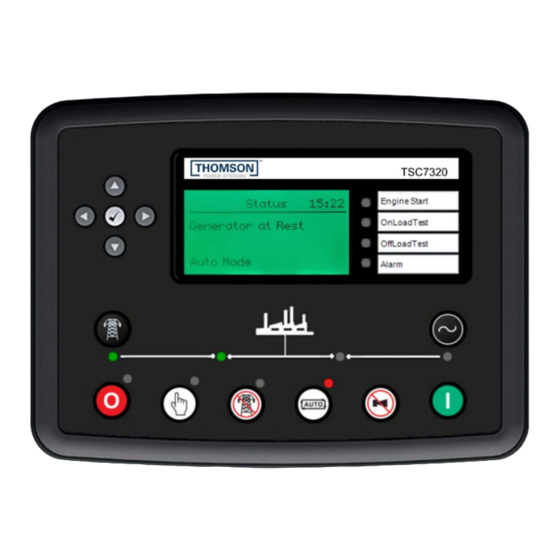
DESCRIPTION The TSC 7320 controller is an all in one unit and does not require any communication cables to operate. The controller has 13 buttons on the front of the controller that can be used to change what the controller is displaying, changing the settings, and control the mechanism. -
Page 15: Controller Input Connections
8 of the inputs are digital inputs, and the other 6 are analogue inputs that can also be programmed to be more digital inputs. Refer to the TSC 7320 Manual for further information on programming changes as required. -
Page 16: Controller Output Connections
The TSC 7320 is provided from the factory with 8 programmable digital outputs and 2 programmable dry contact outputs with default settings per the table shown below. Refer to the TSC 7320 Manual for further information on programming changes as required. The Digital outputs are rated 2A @ 24VDC resistive. -
Page 17: Ats Operation Mode Descriptions
TSC 7320 Transfer Switch Controller 3.4. ATS OPERATION MODE DESCRIPTIONS Mode Description ATS Mechanism Engine Start Output Control Outputs AUTO ATS automatically transfers to Generator (Source 2) during a Outputs automatically operate Output contact closes to start Utility (Source 1) failure and automatically returns power to utility... - Page 18 TSC 7320 Transfer Switch Controller The TSC 7320 requires continuous control power (i.e. utility/gen power on, or 24VDC aux power on) to keep the automatic engine start output disabled. If control power is de-energized, the engine start output will close in approximately 3 minutes, once its internal control power reservoir de-energizes.
-
Page 19: Automatic Sequence Of Operation
NOTE: For specific device settings and ranges, refer to SECTION 6 Factory Default Programming. NOTE: Time delays indicated below are factory default settings only. Refer to TSC 7320 manual for alternate time delay settings available on the TSC 7320 Controller UTILITY POWER... -
Page 20: Open Transition (Fast, In-Phase) Transfer
Following expiry of the utility return timer, the TSC 7320 controller will verify the difference of voltage, frequency and phase angle between the generator and utility... -
Page 21: Closed Transition (Fast, In-Phase) Transfer
For transfer switches equipped with the closed transition transfer option (i.e. ATS Model Code Digit #13 Operation Type 3 or 4), the TSC 7320 is configured to provide additional logic for this application. When the TSC 7320 controller receives an input signal for... - Page 22 NOTE: the TSC 7320 programmable digital input for Service Disconnect mode must be used in conjunction with a Service Disconnect control switch which changes the source of control power to the TSC 7320 output contacts to enable transfer to the neutral position.
-
Page 23: Display Page Descriptions
3.6. DISPLAY PAGE DESCRIPTIONS The TSC 7320 controller monitors the ATS and displays various information which is visible on the front Display or front panel LEDs. Navigating to different screens is controlled by a four navigation buttons, and a center checkmark button. The display has pre-programmed display... -
Page 24: Status Page
3.6.3. ALARMS PAGE The TSC 7320 alarms page displays available alarms and will remain blank if there are no alarms present. If there is more then one alarm, the up and down navigation keys can be used to cycle bewteen them. -
Page 25: Events Log Page
TSC 7320 Transfer Switch Controller 3.6.4. EVENTS LOG PAGE The events log page shows time/date stamped information as to when events have occurred. The controller stores up to 250 events before the information is cleared automatically. 3.6.5. SCHEDULE PAGE The schedule page shows information about the different exercise tests, when they will run, and for how long. -
Page 26: Current Metering Page
TSC 7320 Transfer Switch Controller 3.6.7. CURRENT METERING PAGE The current metering page is a subpage within the generator section, and it displays the measured current as report from the CT’s for each of the lines. NOTE: Load CT ‘s must be supplied with the ATS to provide current and power data. -
Page 27: Operating Instructions
4.1. DISPLAY SCREEN NAVIGATION The TSC 7320 controller has pre-programmed display pages which are selected manually using the buttons on the front of the controller, by pushing the left and right navigation buttons. The display pages are organized into the following order and can be continuously cycled through: Status –... -
Page 28: On Load Test Instructions (Utility Power Fail Simulation)
4.2. ON LOAD TEST INSTRUCTIONS (UTILITY POWER FAIL SIMULATION) To initiate an ATS On Load Test, press the test button on the TSC 7320 controller to enter test mode. Next, press the gen start button (green), and the controller will start the generator and once it reaches the nominal voltage and frequency, the switch will be transferred to the generator and take over the load. -
Page 29: Open/Closed Transition Transfer Operation
TSC 7320 Transfer Switch Controller 4.4. OPEN/CLOSED TRANSITION TRANSFER OPERATION The ATS may be supplied with several different Open or Closed Transition Transfer operational features. The ATS model code depicts the options available as shown below: Operational behavior of an ATS equipped with these different features is depicted in the... -
Page 30: Open Transition In-Sync Transfer Operation (Model X)
TSC 7320 Transfer Switch Controller 4.4.1. Open Transition IN-SYNC Transfer Operation (Model X) If the ATS is supplied with ATS Model X feature (i.e. Open Transition – In-sync Transfer), the ATS will operate as per automatic sequence of operation (open transition) however all transfers will occur using in-sync transfer control sensing instead of neutral delay control logic. -
Page 31: Transfer Fail Alarm Reset
4.7. PHASE SEQUENCE PROTECTION ALARM RESET The TSC 7320 is programmed to generate an alarm if it detects a rotated phase sequence (not A-B-C). The ATS will not transfer to that source until the sequence has been fixed, and the alarm has been cleared. -
Page 32: Programming Instructions
TSC 7320 Transfer Switch Controller PROGRAMMING INSTRUCTIONS 5.1. PASSWORD SECURITY DESCRIPTION/LOGIN There are two different areas to change the controller settings, one of the requires entering a pin to change the settings, and the other are does not require a pin. -
Page 33: Restricted Settings
To prevent un-authorized access, all the other transfer switch settings can only be changed in the restricted area. With the transfer switch energized, follow the procedure below to login to the TSC 7320 controller: • Enter “STOP” mode, by pressing the red button in the lower left corner of the controller. -
Page 34: System Time/Date Adjustment
To adjust the TSC 7320 controller’s internal time clock, follow the detailed procedure below. With the TSC 7320 powered on, navigate to the restricted area of the settings, and login Find the page with the “Editor - Display” heading. If the date and time is not listed, the up or down navigation button may need to be pressed to show the setting ... -
Page 35: Voltage Change Procedure
ONLY changed via software programming. 1. Locating the PIN: First find PINs 14 to 20 on the backside of the TSC 7320 controller. There will be a wire connected to PIN 14, and that wire will have a label specifying it is the voltage selection wire. - Page 36 TSC 7320 Transfer Switch Controller 3. Choosing voltage configuration: There are 5 separate inputs that dictate the different configurations, and they are listed in the table below. Select one of the options below based on the ATS requirements. 4. Inserting the wire: Insert the voltage selection wire into the desired terminal and tighten the screw on the terminal.
-
Page 37: Exercise Timer Setup
5.4. EXERCISE TIMER SETUP The TSC 7320 controller has a built-in calendar based programmable exercise timer. The exercise timer has two banks that can be programmed on either weekly or monthly period. Each of the banks has 8 schedules within them that can be set to a specific week, day, and time. For a given schedule, the type of test and duration can be inputted. -
Page 38: Multi-Stage Load Shed Control
Load Shed strategies are used when the backup generator is not sized to supply all ATS loads. TSC 7320 monitors the generator output KW to determine when to connect or disconnect non-critical loads to maximize utilization and to prevent the generator from overload and shutdown. -
Page 39: System Settings
SECTION 6 Factory Default Programming. The TSC 7320 controller has a couple options that are controller via the input pins. 5.6.1. OPEN TRANSITION All panels have a wire connecting the controllers input E (PIN 52) to the DC negative terminals, and that input will make the controller perform an open transition transfer with a neutral delay. -
Page 40: Remote Off Load Test
TSC 7320 Transfer Switch Controller 5.6.3. REMOTE OFF LOAD TEST If a wire connects the controllers input G (PIN 54) to the DC negative terminals, that input will tell the controller perform an off load test. The controller will run the off load test until the input is removed. -
Page 41: Factory Default Programming
FACTORY DEFAULT PROGRAMMING The TSC 7320 is factory programmed with default settings as shown as per the following table. NOTE: This table is applicable for firmware version R0. Refer to the TSC 7320 O&M Manual for programming instructions to change any default setting. -
Page 42: Tsc 7320 Wiring Pin Connections
TSC 7320 Transfer Switch Controller TSC 7320 WIRING PIN CONNECTIONS PM180 REV 0 23/02/10 Thomson Power Systems... -
Page 43: Troubleshooting
TSC 7320 Transfer Switch Controller TROUBLESHOOTING Several problems can cause the TSC 7320 controller not to function properly. Refer to the following list of typical problems. Consult the factory for any detailed information or for any problems not listed. CAUTION Before opening the enclosure to perform any service task, it is imperative to isolate the transfer switch from any possible source of power. - Page 44 TSC 7320 scheduler Verify correct nominal levels the utility source should be operating at and compare to TSC 7320 settings for Utility supply is not operating at correct under/over voltage, voltage phase balance and voltage or frequency levels.
- Page 45 Close generator set output circuit breaker feeds ATS is open Verify correct nominal levels the generator should be operating at and compare to TSC 7320 Settings for Generator supply is not operating at correct under/over voltage, voltage phase balance and voltage or frequency levels.
- Page 46 Verify Utility side auxiliary switch (U-AUX) n/c contact is closed and is low resistance when Utility switching Faulty Utility power switching device device is open. Verify TSC 7320 Digital input for Utility auxiliary switch Power Switching Device is Open has been activated...
- Page 47 NOTE There are no user serviceable components located on the TSC 7320 printed circuit board. If the TSC 7320 controller is deemed to be defective, they must be returned to the Thomson Power Systems Factory for repair or replacement. Please refer to Product Return Policy section of this manual further information on product return procedures required.
-
Page 48: Replacement Parts
TSC 7320 Transfer Switch Controller REPLACEMENT PARTS Replacement parts are available for the transfer switch as follows: NOTE When ordering replacement parts please provide the following information: - Transfer Switch Model code (e.g. TS 873AA0200AS) - Transfer Switch Serial Number (e.g. W-022345) -
Page 49: Product Return Policy
Returns only: Email sales@thomsonps.com Warranty replacement/Warranty Repair: Email support@thomsonps.com Upon receipt of your request Thomson Power Systems will confirm with a copy of our order acknowledgement, advising the RMA number which should be used to tag the defective controller prior to shipment. -
Page 50: Notes
TSC 7320 Transfer Switch Controller NOTES ________________________________________________________________________________ ________________________________________________________________________________ ________________________________________________________________________________ ________________________________________________________________________________ ________________________________________________________________________________ ________________________________________________________________________________ ________________________________________________________________________________ ________________________________________________________________________________ ________________________________________________________________________________ ________________________________________________________________________________ ________________________________________________________________________________ ________________________________________________________________________________ ________________________________________________________________________________ ________________________________________________________________________________ ________________________________________________________________________________ ________________________________________________________________________________ ________________________________________________________________________________ ________________________________________________________________________________ ________________________________________________________________________________ ________________________________________________________________________________ ________________________________________________________________________________ ________________________________________________________________________________ ________________________________________________________________________________ ________________________________________________________________________________ ________________________________________________________________________________ PM180 REV 0 23/02/10 Thomson Power Systems... - Page 51 TSC 7320 Transfer Switch Controller PM180 REV 0 23/02/10 Thomson Power Systems...
Need help?
Do you have a question about the TSC 7320 and is the answer not in the manual?
Questions and answers