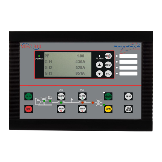
THOMSON MEC 310 - APLLICATION NOTES EXTERNAL I-O MODULES Application Notes
Feature (exp) external i/o modules
Hide thumbs
Also See for MEC 310 - APLLICATION NOTES EXTERNAL I-O MODULES:
- Manual (22 pages) ,
- Application notes (19 pages) ,
- Operator's manual (11 pages)
Table of Contents
Advertisement
Quick Links
Download this manual
See also:
Application Note
Advertisement
Table of Contents

Summary of Contents for THOMSON MEC 310 - APLLICATION NOTES EXTERNAL I-O MODULES
- Page 1 MEC 310 APPLICATION NOTES FEATURE (EXP) External I/O modules r. 0524B PM0104 Rev 0 09/08/20 9087A – 198 Street, Langley, BC Canada V1M 3B1 Telephone (604) 888-0110 Telefax (604) 888-3381 E-Mail: info@thomsontechnology.com www.thomsontechnology.com...
- Page 2 This description of options covers the following products: MEC 310 SW version 1.2X.X...
-
Page 3: Table Of Contents
MEC 310 APPLICATION NOTES - External I/O Modules Table of Contents WARNINGS AND LEGAL INFORMATION ..................1 ....................1 EGAL INFORMATION AND RESPONSIBILITY ....................1 LECTROSTATIC DISCHARGE AWARENESS .............................1 AFETY ISSUES ............................1 ACTORY SETTINGS ..............................1 EFINITIONS DESCRIPTION OF OPTION ......................2 EXP ..............................2 EATURE MEC 310 ...........................2... -
Page 4: Warnings And Legal Information
Thomson Technology takes no responsibility for installation or operation of the generator set. If there is any doubt about how to install or operate the engine controlled by the unit, the company responsible for the installation or the operation of the set must be contacted. -
Page 5: Description Of Option
CANopen description. MEC 310 interface Wiring details: Please refer to the document ‘Installation Instructions and Reference Handbook’. Terminal description The CAN #2 terminals 57(H) and 59(L) are also used for EAP 300 (see feature EAP 300). Terminals Function Description CAN-H... -
Page 6: Installation Of Beckhoff Controller (Bus Coupler)
MEC 310 APPLICATION NOTES - External I/O Modules Installation of Beckhoff controller (bus coupler) The following is a step-by-step guide to set up the communication between the MEC 310 unit and the Beckhoff modules. Documentation regarding Beckhoff modules can be found at www.beckhoff.com. - Page 7 12. To see the available external I/Os, retrieve the parameters from the MEC 310 unit with the TPS 300 software. 13. Click on ‘External I/O’ in the TPS 300 software to see or change settings for external I/O modules. PM104 R0 09/08/20...
-
Page 8: Functional Description
MEC 310 APPLICATION NOTES - External I/O Modules 3. Functional description Supported modules The MEC 310 supports communication with the Beckhoff CANopen I/O modules. The following CANopen modules are available from Thomson Technology: Controller (bus coupler) – MANDATORY COMPONENT Type... -
Page 9: Functional Check Of External I/Omodules
External I/Os will only be shown in the TPS 300 software if they are present. The result of the check can be read in status channels 12950-12983. The Beckhoff module transmits a status message to the unit. This message is a HEX value for digital I/O units and decimal for controllers/analogue I/O units. - Page 10 2. digit: Number of input/output (2, 4 or 8) 3. digit: Not used (0) 4. digit: Input [1] or output [2] In the TPS 300 software, all values are presented as decimal values, so the HEX values for the digital I/O modules are translated as follows: Inputs:...
- Page 11 A 4-digit decimal value is presented. This number represents the module version used. Examples for analogue I/O modules Module Value EXP-AI4 (KL3444) 3204 The module check is only carried out when resetting the communication (parameter 7974 or 7984). PM104 R0 09/08/20 Page 8 THOMSON TECHNOLOGY...
-
Page 12: Parameter List
Module 3 10-1200 ohm (2-wire) 7954 KL320x config Module 4 The above selections for KL3202/3204 cannot be changed. After changing module type, the parameter list in the TPS 300 software must be uploaded again. PM104 R0 09/08/20 Page 9 THOMSON TECHNOLOGY... -
Page 13: External I/Osetup
Enable Same order for settings 12030-12230. Analogue outputs The external analogue outputs are used as transducer outputs in menu 5820 to 5970. Please refer to the description of option E+F. MEC 310 does not support analogue outputs. PM104 R0 09/08/20... - Page 14 MEC 310 APPLICATION NOTES - External I/O Modules Digital inputs 12540 Ext. dig. in 1 Setting Min. Max. Factory setting setting setting 12540 Ext. dig. in 1 Delay 2.0 s 600.0 s 10.0 s Fail class MEC 310 unit dependent...
-
Page 15: Fault Finding
MEC 310 APPLICATION NOTES - External I/O Modules 5. Fault finding Beckhoff controllers LC5100 BK5120 BK5150 PM104 R0 09/08/20 Page 12 THOMSON TECHNOLOGY... -
Page 16: Diagnostic Leds
MEC 310 APPLICATION NOTES - External I/O Modules Diagnostic LEDs The Beckhoff controllers have LEDs for display of status. They can be used for fault finding. CAN ERR blink code CAN ERR Meaning CANbus has no errors . Automatic Baud rate detection has not yet Fast blinking (Approx. - Page 17 Two LEDs, the K-bus LEDs, indicate the operational state of the bus terminals and the connection to these bus terminals. The green LED (I/O RUN) lights up in order to indicate fault-free operation. The red LED (I/O ERR) flashes with two different frequencies in order to indicate an error. The...
- Page 18 - Only use digital terminals or bus 7 pulses Unsupported terminal coupler BK5120. detected at location n All information regarding error codes is related to the documentation from: http://www.beckhoff.com/ Thomson Technology reserves the right to change any of the above PM104 R0 09/08/20 Page 15...


Need help?
Do you have a question about the MEC 310 - APLLICATION NOTES EXTERNAL I-O MODULES and is the answer not in the manual?
Questions and answers