Table of Contents
Advertisement
Quick Links
Download this manual
See also:
Operating Manual
Advertisement
Table of Contents

Subscribe to Our Youtube Channel
Related Manuals for THOMSON MEC 320


Summary of Contents for THOMSON MEC 320
- Page 1 MEC 320 SW version 3.3.X.X OPERATOR’S MANUAL • Display readings • Push-button functions • Alarm handling • Log list PM106 Rev 0 10/02/02 9087A – 198 Street, Langley, BC Canada V1M 3B1 Telephone (604) 888-0110 Telefax (604) 888-3381 E-Mail: info@thomsontechnology.com www.thomsontechnology.com...
-
Page 3: Table Of Contents
AFETY ISSUES ............................3 EFINITIONS DISPLAY PUSH-BUTTONS AND LEDS................. 4 ........................4 BUTTON FUNCTIONS ..........................6 FUNCTIONS DISPLAY AND MENU STRUCTURE ..................8 ............................. 8 DISPLAY ..........................8 ENU STRUCTURE ..........................12 TATUS LINE TEXT ALARM HANDLING AND LOG LIST.................. 17 .......................... -
Page 4: About This Document
Intended users This Operator’s Manual is mainly intended for the daily user. On the basis of this document, the operator will be able to carry out simple procedures such as start/stop and control of the generator set. Contents/overall structure The document is divided into chapters, and in order to make the structure simple and easy to use, each chapter will begin from the top of a new page. -
Page 5: Warnings And Legal Information
THOMSON TECHNOLOGY takes no responsibility for installation or operation of the generator set. If there is any doubt about how to install or operate the generator set controlled by the unit, the company responsible for the installation or the operation of the set must be contacted. -
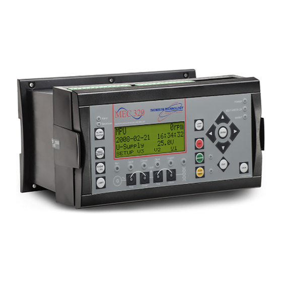
Page 6: Display Push-Buttons And Leds
Increases the value of the selected set point (in the setup menu). In the daily use display, this button function is used for scrolling the View lines in V1 or the second line (in the setup menu) displaying of generator values. - Page 7 MEC 320 OPERATOR’S MANUAL The push-buttons are placed as follows: Alarm Status: Shift the display three lower lines the alarm list Reset/Silence: Resets an alarm and or silence the horn Event log: Shift the display three lower lines the alarm list Jump: Enter a specific menu number selection.
-
Page 8: Led Functions
MEC 320 OPERATOR’S MANUAL LED functions The display unit holds 10 LED functions. The colour is green or red or a combination in different situations. Alarm: LED flashing indicates that unacknowledged alarms are present. LED fixed light indicates that all alarms are acknowledged, but some are still present. - Page 9 MEC 320 OPERATOR’S MANUAL The display LEDs are indicating as follows: Power: Indicates auxiliary supply ON Alarm: Flashing: Unacknowledged alarms present. Self check OK: Indicates self check OK Fixed: Acknowledged alarms present. Inhibit: Indicates alarm inhibit active. Auto: ON. Semi-auto: OFF Generator OK.
-
Page 10: Display And Menu Structure
Entry window When the unit is powered up, an entry window appears. The entry window is the turning point in the menu structure and as such the gateway to the other menus. It can always be reached by pushing the EXIT push-button 3 times. - Page 11 In the view menus, various measured values are on display. View menu navigation The readings etc. are all selected by moving the cursor (fourth display line (note the underscore on V1 on the drawing above - this is the cursor)): The cursor is moved using the push-buttons on the right side of the display.
- Page 12 (above). Line 2 and line 3 show measurements. * The default window is automatically selected after the ramping up when the gen-set is in normal operation, e.g. fixed power mode. View window 3 Display of measured values according to the selections made during configuration.
- Page 13 MEC 320 OPERATOR’S MANUAL First display line indicates running status of the unit. The messages shown in the table at the end of this chapter can be displayed. Second and third display lines display measured values. Fourth display line displays the selection line.
-
Page 14: Status Line Text
MEC 320 OPERATOR’S MANUAL Status line text This table explains the different messages. Status text Condition Comment BLOCK Block mode is activated SIMPLE TEST LOAD TEST Test mode is activated FULL TEST SIMPLE TEST ###.#min Test mode activated and LOAD TEST ###.#min... - Page 15 Status text Condition Comment ACCESS LOCK The configurable input is activated, and the operator tries to activate one of the blocked keys GB TRIP EXTERNALLY Some external equipment An external trip is logged has tripped the breaker in the event log...
- Page 16 Power management has Option G5 must be been deactivated and no available other gen-set mode has been selected Texts only related to Power Management (option G5) Status text Condition Comment DG unit BLACKOUT ENABLE This information is shown if a...
- Page 17 MEC 320 OPERATOR’S MANUAL Status text Condition Comment AUTO OPERATION BTB unit in Auto, but not ready for breaker operation (active ‘BTB trip’ alarm) BLOCKED FOR CLOSING Last open BTB in a ring bus BTB TRIP EXTERNALLY Some external equipment has...
- Page 18 MEC 320 OPERATOR’S MANUAL View menu example The following is an example of a configured view menu system. In this example, 4 of 15 windows have been configured in view 1. MEC320 MANUA G-L1 50Hz 2006-08-18 B-L1 50Hz SETU SETU...
-
Page 19: Alarm Handling And Log List
5. Alarm handling and log list Alarm handling When an alarm occurs, the unit will automatically go to the alarm list for display of the alarm. If reading of the alarms is not desired, use the EXIT push-button to exit the alarm list. -
Page 20: Log List
2. Alarms 3. Battery test The log list contains up to 150 events, the alarm list contains up to 30 historical alarms and the battery test list contains up to 52 historical battery tests. An event is e.g. closing of breaker and starting of engine. An alarm is e.g. overcurrent or high cooling water temperature.
Need help?
Do you have a question about the MEC 320 and is the answer not in the manual?
Questions and answers