Advertisement
Quick Links
Cod. 6331856B - 02/2024 - R0
EN
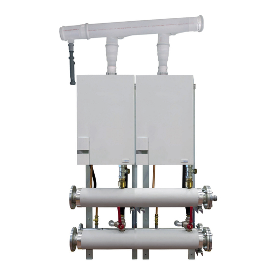
MURELLE EQUIPE 220-660 ErP
(PACK OF 2-6 MURELLE HE 110 R ErP)
INSTALLATION AND SERVICING INSTRUCTIONS
ENSURE THAT THESE
INSTRUCTIONS ARE LEFT
FOR THE USER AFTER
COMPLETION OF THE
BENCHMARK SECTION
PLEASE READ THE
IMPORTANT NOTICE
WITHIN THIS GUIDE
REGARDING YOUR BOILER
WARRANTY
199839
ORIGINAL INSTRUCTIONS
Advertisement

Related Manuals for Sime MURELLE EQUIPE 220 ErP


Summary of Contents for Sime MURELLE EQUIPE 220 ErP
- Page 1 Cod. 6331856B - 02/2024 - R0 MURELLE EQUIPE 220-660 ErP (PACK OF 2-6 MURELLE HE 110 R ErP) INSTALLATION AND SERVICING INSTRUCTIONS ENSURE THAT THESE INSTRUCTIONS ARE LEFT FOR THE USER AFTER COMPLETION OF THE BENCHMARK SECTION PLEASE READ THE IMPORTANT NOTICE WITHIN THIS GUIDE REGARDING YOUR BOILER...
- Page 2 SAFE HANDLING This boiler may require 2 or more operatives to move it into its installation site, remove it from its packaging and during movement into its installation location. Manoeuvring the boiler may include the use of a sack truck and involve lifting pushing and pulling.
-
Page 3: Table Of Contents
IPX4D CONTENTS MODULAR SYSTEM DESCRIPTION ......................page FRAME ASSEMBLY OF SINGLE MODULE SUPPORT .................. page FITTING CONNECTION AND CONDENSATE DRAIN ................... page ASSEMBLE THE CASCADE FLUE ........................ page CASCADE CONNECTION ..........................page CASCADE MANAGEMENT ........................... page APPENDIX (GUIDANCE HHIC) ........................page APPENDIX 2 (VENTILATION GUIDENCE) .................... -
Page 4: Modular System Description
MODULAR SYSTEM DESCRIPTION INTRODUCTION Cascade Flue code 9000220 Boilers and Mounting Frames and He- – MURELLE EQUIPE 330 ErP aders code 9001550 This manual is for the construction main- Boilers and Mounting Frames and He- Low Loss Header Connection Kit code tenance and operation of a modular unit aders code 9001330 8101533... - Page 5 1.2.2 MURELLE EQUIPE 440-550 ErP (fig. 1/b) MURELLE EQUIPE 440-550 UK ø D DIMENSIONS FIXTURES Murelle Equipe 440 ErP 550 ErP C.H. flow (Flange PN6-DN100) 2208 2760 C.H. return (Flange PN6-DN100) 2360 2394 Gas (Flange PN6-DN50) Fig. 1/b S3 Condensation drain ø 40 1.2.3 MURELLE EQUIPE 660 ErP (fig.
- Page 6 TECHNICAL SPECIFICATIONS MURELLE EQUIPE 220-550 ErP MURELLE EQUIPE 220 ErP 330 ErP 440 ErP 550 ErP Heat output Nominal (80-60°C) (Pn max) 212,6 (2 x 106,3) 318,9 (3 x 106,3) 425,2 (4 x 106,3) 531,5 (5 x 106,3) Nominal (50-30°C) (Pn max) 229.2 (6 x 114.6) 343.8 (3 x 114.6) 458.4 (4 x 114.6) 573.0 (2 x 114.6)
- Page 7 TECHNICAL SPECIFICATIONS MURELLE EQUIPE 660 ErP MURELLE EQUIPE 660 ErP Heat output Nominal (80-60°C) (Pn max) 637,8 (6 x 106,3) Nominal (50-30°C) (Pn max) 687.6 (6 x 114.6) Minimum (80-60°C) (Pn min) 21.1 Minimum (50-30°C) (Pn min) 23.6 Heat input (*) Nominal (Qn max - Qnw max) 648.0 (6 x 108.0) Minimum (Qn min - Qnw min) 21.6...
- Page 8 HYDRAULIC CIRCUIT (fig. 2) 19 ------- 1 Cascade supply probe (SMC) 20 ------- 2 Low Loss Header 21 ------- 3 Loss Header Connection Kit 22 3-way drain tap 5 Condensate drain trap 23 ------- 6 Gas valve 24 Single module drain 7 ------- 25 Gas tap 8 Fan...
- Page 9 AVAILABLE PREVALENCE TO THE SYSTEM, COLLECTORS DELIVERY AND SUPPLY FITTINGS “MURELLE EQUIPE 660 ErP” (fig. 3/a) CAPACITY (m PORTATA (m Fig. 3/a PRESSURE DROPS OF THE HYDRAULIC COMPENSATOR SUPPLIED UPON REQUEST WITH KIT CODE 8101552/53 (fig. 4) CAPACITY (m PORTATA (m Fig.
- Page 10 - mixed zone kit code 8092275/76 configuration devices OPTIONAL - SOLAR kit code 8092277 SIME HOME e RVS with electronic boiler - MODBUS kit code 8092278 which allows board set PAR 10. The electronic boiler board is prepa- to MODBUS communication cascade...
- Page 11 1.11 COMPOSITION OF THE KIT (fig. 5) Pmax – N. 2 frames code 6294800 (MURELLE EQUIPE 220 ErP) – N. 3 frames code 6294800 (MURELLE EQUIPE 330 ErP) – N. 4 frames code 6294800 (MURELLE EQUIPE 440 ErP) – N. 5 frames code 6294800 (MURELLE EQUIPE 550 ErP) Pmin –...
- Page 12 COD. 6296530 L= 170 COD. 5192954 COD. 6296530 L= 170 COD. 5192954 COD. 6296530 L= 170 COD. 519295 – N. 1 blind flange PN6 DN 50 for gas collector with gasket COD. 629651 and fixing screws, code 6105150 L=250 – N. 2 blind flanges PN6 DN 100 for system delivery/return collectors with gasket and fixing screws, code 6105155 Fig.
- Page 13 KIT CO MURELLE EQUIPE 220 ErP – MURELLE EQUIPE 220 ErP KIT COLLETTORE FUMI “MURELLE EQUIPE 220 ErP” fume exhaust unit consisting of: cod. 6 (A = 7 N. 2 ø 200 collectors code 5192954 COD. 5192961 N. 2 L. 170 ø 80 extensions code 6296530 cod.
- Page 14 KIT COLLETTORE FUMI “MURELLE EQUIPE 550 ErP” COD. 5192961 COD. 5192954 COD. 6296530 L= 170 COD. 5192954 COD. 6296530 COD. 5192954 L= 170 COD. 6296530 COD. 5192954 L= 170 – MURELLE EQUIPE 550 ErP fume exhaust unit consisting of: N. 5 ø 200 collectors code 5192954 COD.
- Page 15 – N. 1 sensor kit, code 8092250 with external temperature sensor (SE), ca- scade delivery sensor (SMC) and RS- 485 board connection cable NOTE: Section 5 show the electrical con- nection for the sensors. Fig. 5/l 1.12 KIT CODE 8101532 MURELLE EQUIPE 220-330 ErP (to be requested separately) (fig.
- Page 16 1.13 KIT CODE 8101533 “MURELLE EQUIPE 440-550-660 ErP” (to be requested separately) (fig. 7) – N. 1 kit with collector delivery tube, code 6291969, collector return tube, code 6291971, 8 litres expansion vessel, code 6245108, expansion vessel connection tube, code 6227661, reduced nipple 1” - 3/4”, code 2040252, gaskets, nuts and M16 fixing screws Fig.
-
Page 17: Frame Assembly Of Single Module Support
FRAME ASSEMBLY OF SINGLE MODULE SUPPORT Assemble the boiler supports using the TE M8 x 75 screws and the L=52 spacer. Secure the assembled frames to the wall or other secure structure. - Page 18 Mount the collector supporting brackets, fastening them to the frame using the washers and M10 nuts. The position where to place the washer and bracket blocking nut is indi- cated by two arrows in correspondence with the frame studs to be used. Mount the supports of the condensate drain collector, fastening them to the supporting brackets, using the M5 screws.
-
Page 19: Fitting Connection And Condensate Drain
FITTING CONNECTION AND CONDENSATE DRAIN Place the condensate drain collector inside the appropriate support. Connect the condensate drain of each module to the collector. Condensate drain connection to the boiler... - Page 20 Mount the blind flanges with gaskets to the gas hea- der using the screws and M12 nuts. Secure the gas header using the screws, washers and M8 nuts. Mount the blind flanges with gaskets to the delive- ry/return headers using the screws and M12 nuts. Secure them to the brackets using the screws, washers and M8 nuts.
- Page 21 C.H. flow C.H. return L=31 Mount the series of three-way drain cocks and the system delivery/gas cocks to the NIPPLE 3/4” SHAFT DIRECTION relative collectors and connect the tubes DRAIN BALL ADJUSTMENT CURVE to the fittings of the boiler using the respective gaskets.
- Page 22 Low Loss Header connection kit (to be requested separately). Use the gaskets with screws and MURELLE EQUIPE 220-330 ErP M16 fixing nuts for the assembly. MURELLE EQUIPE 440-550-660 ErP...
- Page 23 Low Loss Header (to be requested MURELLE EQUIPE 220-330 ErP separately). Use the gaskets and fasten it to the connection outlets using the screws and M16 nuts provided. MURELLE EQUIPE 440-550-660 ErP...
-
Page 24: Assemble The Cascade Flue
Apre be exited automatically or by pressing one of In these cases, use ø 80 polypropylene accessories, the command buttons (2), except the RESET. authorised and customised by SIME (refer to the instruction manual provided with the boiler). INSTALLER BUTTONS Provided with each boiler there is a ø... -
Page 25: Cascade Connection
CASCADE CONNECTION WARNING: The manufacturer is not responsible for any damage caused by failure to earth the appliance or failure to observe the information provided in the wiring diagrams WARNING: The external temperature sensor “SE” is OBLIGATORY and MUST be connected to the master boiler ATTENTION: The “SMC”... -
Page 26: Cascade Management
CASCADE MANAGEMENT Apre INSTALLER BUTTONS... - Page 27 SERVICE & INTERIM BOILER WORK RECORD It is recommended that your boiler and heating system are regularly serviced and maintained, in line with manufacturers’ instructions, and that the appropriate service / interim work record is completed. Service provider When completing a service record (as below), please ensure you have carried out the service as described in the manufacturers’ instructions. Always use the SERVICE/INTERIM WORK ON BOILER SERVICE/INTERIM WORK ON BOILER Date:...
- Page 28 SERVICE & INTERIM BOILER WORK RECORD It is recommended that your boiler and heating system are regularly serviced and maintained, in line with manufacturers’ instructions, and that the appropriate service / interim work record is completed. Service provider When completing a service record (as below), please ensure you have carried out the service as described in the manufacturers’ instructions. Always use the SERVICE/INTERIM WORK ON BOILER SERVICE/INTERIM WORK ON BOILER Date:...
- Page 31 APPENDIX (GUIDANCE HHIC - October 2018 Issue 1.0) Manufacturer's Instructions The latest manufacturer’s instructions shall be followed for the correct connection of the condensate discharge pipe from the boiler as this may vary due to the design of the boiler. For example, a trap is not required in the condensate discharge pipework if there is a trap with a minimum condensate seal of 75 mm incorporated into the boiler.
- Page 32 Figure 1 – Connection of condensate discharge pipe to internal soil and vent stack. Note – Refer to manufacturer’s instructions Boiler Minimum internal diameter 19 mm Soil and vent stack 450 mm minimum up to three storeys Invert Manufacturers Instructions shall be referred to when installing boiler condensate discharge pipes...
- Page 33 Internal Condensate Pipe Connection with External Termination Figure 2(a) – Connection of a condensate discharge pipe downstream of a sink, basin, bath or shower waste trap. Note – Check manufacturer’s instructions to see if an air break or trap is required. Boiler Visible air break 75 mm trap...
- Page 34 Internal Condensate Pipe Connection with External Termination Figure 2(b) – Connection of a condensate discharge pipe downstream of a sink, basin, bath or shower waste trap Boiler Visible air break at plug hole – 75 mm sink, basin, bath or shower waste trap Sink, basin, bath or shower with integral overflow Open end of condensate discharge pipe direct into gully 25 mm min below grating but above water level;...
- Page 35 Internal Condensate Pipe Discharge Termination When connecting to existing pipework it is critical to review the existing installation to ensure the existing pipework is appropriate for condensate discharge having been run correctly and fully insulated and sealed if this is an external or internal termination. The possibility of waste pipes freezing downstream of the connection point shall be con- sidered when determining a suitable connection point - e.g.
- Page 36 External Connections External Connections External Connections Only fit a correctly insulated external boiler condensate drain connection if an internal gravity or pumped connection is impractical to install. The pipe work from the boiler shall be of a minimum 19mm ID or if in an unheated area increased to 30mm ID (typically 32mm OD) solvent weld of as per manufacturer’s instructions and the condensate discharge pipe shall be run in a standard drainpipe material, e.g.
- Page 37 External Connections Figure 3 – Connection of condensate discharge pipe to external soil and vent stack Boiler Internal Trap Visible air break and trap not required if there is a trap with a minimum condensate seal of 75mm incorporated into the boiler. Soil and vent stack Invert 450mm minimum up to three storeys...
- Page 38 External Connections onnecting to a rain water downpipe/External Soil Stack When a rain water downpipe is used as the termination (NB only permissible if this downpipe passes to a combined foul and rainwater drainage system) an external air break shall be installed between the condensate discharge pipe and the downpipe to avoid reverse flow of rainwater into the boiler should the downpipe itself become blocked, flooded or frozen.
- Page 39 External Connections Figure 4 – External termination to rainwater downpipe (NB only combined foul/rainwater drain) Condensate discharge pipe from boiler Pipe size transition point Water/weather proof, UV resistant insulation 43mm 90° male/female bend External rain water pipe into foul water External air break Air gap 68mm PVCu strap on fitting...
- Page 40 External Connections Figure 5 – Preferred Method: External drain, gully or rainwater hopper Boiler Visible air break 38mm minimum trap Visible air break and trap not required if there is a trap with a minimum condensate seal of 38 mm incorporated into the boiler – refer to manufacturer's instructions External length of pipe 3 m maximum Open end of condensate discharge pipe direct into gully 25 mm min below grating but above water level;...
- Page 41 External Connections Figure 6 – Example of a purpose made soakaway Condensate discharge pipe from boiler Ground (this section of the condensate discharge pipe may be run either above or below round level); End cut at 45° Diameter 100 mm minimum plastic tube Bottom of tube sealed Limestone chippings Two rows of three 12 mm holes at 25 mm centres, 50 mm from bottom of tube and facing...
- Page 42 Other considerations Unheated Areas in Buildings Internal condensate drainage pipes run in unheated areas such as lofts, basements and garages shall be treated as external connections and insulated accordingly. Weather proof materials may not be necessary but where separate sections of insulation join together, including elbow joints then these should be connected, insulated and sealed correctly to prevent them coming apart with a suitable material to help prevent freezing.
- Page 43 Alternative Solutions Cold weather protection Cold weather protection methods approved or endorsed by boiler manufacturers and/ or service organisations may be adopted if these are considered suitable by the parties involved. It is the responsibility of the manufacturer of these products to ensure they have completed the necessary testing or calculations to ensure the product offers suitable protection to prevent the condensate pipe from freezing.
- Page 44 Annex A Annex A Note – Annex A details remedial actions for householders which can be taken if a condensate discharge pipe freezes. This may result in requests for alter- ation to condensate discharge pipework, in which case the guidance above should be followed.
- Page 45 Annex A Your Engineer has identified the potential for your boiler to freeze in extreme conditions as the following: Risk category Explanation Engineer selection High risk of freezing- TAKE ACTION AMBER Medium risk of freezing- Strongly advise action to be taken GREEN Low risk but some improvement required...
- Page 46 Annex A Customer advice in extreme cold weather conditions Thawing Frozen Condensate Pipes Below is an explanation of what you would need to do to resolve the problem in the event that the pipe was to freeze. We would highly recommend getting a professional to assess the situation and resolve the problem by upgrading the condensate.
-
Page 47: Appendix 2 (Ventilation Guidence)
APPENDIX 2 (VENTILATION GUIDENCE) Ventilation Requirements for “Murelle Equipe 220 – 660 ErP” Cascade This information is provided for guidance only BS6644:2005 requires the temperatures in the room or compartment not to exceed certain levels: 25°C up to 100 mm from floor level 32°C 1500 mm above floor level 40°C 100 mm from ceiling level The following provided for guidance only, and assumes the ventilation air is taken directly from outside. - Page 48 Sime Ltd Unit 6 Flockton Park Holbrook Avenue Holbrook Industrial Estate, Sheffield, S20 3PP Phone: 0345 901 1114 www.sime.co.uk Email: enquiries@sime.co.uk...
Need help?
Do you have a question about the MURELLE EQUIPE 220 ErP and is the answer not in the manual?
Questions and answers