Sime 25 BF Installer's Instructions
Hide thumbs
Also See for 25 BF:
- Manual (108 pages) ,
- Installer's instructions (59 pages) ,
- User instructions (12 pages)
Advertisement
Quick Links
INSTALLER INSTRUCTIONS
CONTENTS
1
DESCRIPTION OF THE BOILER . . . . . . . . . . . . . . . . . . . . . . . . . . . . . . . . . . . . . . . . . . . . . . . . . . . . . . . . . . . . . . . . . pag. 94
2
INSTALLATION . . . . . . . . . . . . . . . . . . . . . . . . . . . . . . . . . . . . . . . . . . . . . . . . . . . . . . . . . . . . . . . . . . . . . . . . . . . . . . . pag. 98
3
CHARACTERISTICS . . . . . . . . . . . . . . . . . . . . . . . . . . . . . . . . . . . . . . . . . . . . . . . . . . . . . . . . . . . . . . . . . . . . . . . . . . . pag. 108
4
USE AND MAINTENANCE . . . . . . . . . . . . . . . . . . . . . . . . . . . . . . . . . . . . . . . . . . . . . . . . . . . . . . . . . . . . . . . . . . . . . pag. 111
When carrying out commissioning of the boiler, you are highly recommended to perform the following checks:
– Make sure that there are no liquids or inflammable materials in the immediate vicinity of the boiler.
– Make sure that the electrical connections have been made correctly and that the earth wire is connected to a
good earthing system.
– Open the gas tap and check the soundness of the connections, including that of the burner.
– Make sure that the boiler is set for operation for the type of gas supplied.
– Check that the flue pipe for the outlet of the products of the combustion is unobstructed and has been properly
installed.
– Make sure that any shutoff valves are open.
– Make sure that the system is charged with water and is thoroughly vented.
– Check that the circulating pump is not locked (CAUTION: Remember to release the pump coupled with the control
panel, if necessary, to protect the electronic control card).
– Purge the system, bleeding off the air present in the gas pipe by operating the pressure relief valve on the gas
valve inlet.
– Check that the syphened drip is fully filled with water. If necessary, fill it via the special opening.
FONDERIE SIME S.p.A. of Via Garbo 27 - Legnago (VR) - Italy declares that its hot water boilers, which bear the CE
mark under Gas Directive 90/396/CEE and are fitted with a safety thermostat calibrated to a maximum of 110°C,
are not subject to application of PED Directive 97/23/CEE as they meet the requirements of article 1 paragraph
3.6 of the Directive.
IMPORTANT
Advertisement

Subscribe to Our Youtube Channel
Related Manuals for Sime 25 BF


Summary of Contents for Sime 25 BF
-
Page 1: Installer Instructions
– Check that the syphened drip is fully filled with water. If necessary, fill it via the special opening. FONDERIE SIME S.p.A. of Via Garbo 27 - Legnago (VR) - Italy declares that its hot water boilers, which bear the CE mark under Gas Directive 90/396/CEE and are fitted with a safety thermostat calibrated to a maximum of 110°C,... -
Page 2: Description Of The Boiler
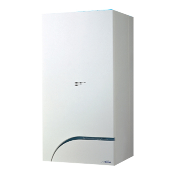
“BT100” separate tank unit. microprocessor technology for function – “PLANET DEWY 25 BF - 30 BF” control and management. C.H. and D.H.W production, with electro- The instructions given in this manual are... - Page 3 TECHNICAL FEATURES 25 BF 25 BFT 30 BF 30 BFT Heat output Nominal (80-60°C) kW (kcal/h) 24,0 (20.600) 24,0 (20.600) 29,3 (25.200) 29,3 (25.200) Minimum (80-60°C) kW (kcal/h) 8,6 (7.400) 8,6 (7.400) 10,4 (9.000) 10,4 (9.000) Nominal (50-30°C) kW (kcal/h) 26,4 (22.700)
- Page 4 FUNCTIONAL DIAGRAM “BF” model 1 Fan 2 Water-gas exchanger 3 Breather valve 4 Gas valve 5 D.H.W. exchanger 6 Diverter valve with charging 7 C.H. sensor (SM) 8 100°C safety stat 9 Air relief valve 10 Circulation pump 11 Expansion vessel 12 Safety valve 13 Boiler discharge 14 Water pressure transducer...
- Page 5 MAIN COMPONENTS “BF” model 1 Control panel 2 D.H.W. exchanger 3 Gas valve 4 Gas rate adjuster 5 Positive pressure take-off 6 Breather valve 8 Sensing electrode 9 Water-gas exchanger 10 Limit stat 11 Ignition electrode 12 Fan 13 Negative pressure take-off 14 Gas pressure take-off 15 Automatic breather 16 100°C safety stat...
- Page 6 INSTALLATION The boiler must be installed in a fixed loca- 2.2. 1 System connection unions the meter to the module, both capacity tion and only by specialized and qualified volume (consumption) in m /h and gas firms in compliance with all instructions The following optional accessories are avail- density must be taken into account.
- Page 7 – “25 BF - 30 BF” models: using the fill cock on the pressure switch valve (2 fig. 5). 1a-b Coaxial duct kit code 8096250 – “25 BFT - 30 BFT” model: using the fill Extension L. 1000 code 8096150 cock (29 fig.
- Page 8 1 Vertical extension L. 140 with take-off points code 8086950 2a Extension L. 1000 code 8096150 2b Extension L. 500 code 8096151 3 Tile with articulation joint code 8091300 4 Roof outlet terminal L. 1285 code 8091205 5 Supplementary 90° elbow code 8095850 6 Supplementary 45°...
- Page 9 stic pipe around 100 to 150 mm in dia- meter, and condensation must be sipho- ned off at the foot of the pipe. The usable height of the water trap must be at least 150 mm. 2.7.3 Separate-pipes roof outlet The roof outlet terminal L.
- Page 10 For lengths up to 25 m, use cables of sec- low safety voltage requirements of EN tion 0.25 mm , for longer lengths up to 50 NOTE: SIME declines all responsibility for 60730. m use cables of section 0.5 mm injury or damage to persons, animals or...
- Page 11 2.9.5 Wiring diagram “PLANET DEWY 25 BF - 30 BF” EV1 Gas valve coil Logica Remote Control (optional) EV2 Gas valve coil Ventilator board Ignition electrode Time programmer Sensing electrode Smoke stat 100°C safety stat TPA Water pressure transducer Note: The room stat (TA) must be...
- Page 12 2.9.6 Wiring diagram “PLANET DEWY 25 BFT - 30 BFT” EV1 Gas valve coil Logica Remote Control (optional) EV2 Gas valve coil Ventilator board Ignition electrode Time programmer Sensing electrode Smoke stat 100°C safety stat TPA Water pressure transducer Note: The room stat (TA) must be Motor-operated diverter valve connected to the terminals 5-6 Pump...
- Page 13 2. 1 0 LOGICA REMOTE CONTROL vious day. ne system with external contact or – Holiday programme: the programme is through a window contact. All the boiler's functions can be managed interrupted for the holiday period and – Anti-bacterial. by a optional digital multifunctional device automatically restarted on returning code 8092204 for the remote of the boi- home.
- Page 14 Maximum limit of delivery The delivery temperature is limited to the maximum set value. temperature Variation of the maximum speed of the The increase per minute of the prescribed delivery temperature value sent delivery temperature in °C is limited to the imposed value. Activation of adaptation With the activation of the adaptation, the pre-set value transmitted to the boiler regulator is adapted to the effective heat need.
- Page 15 Entrance function terminal 3-4 The freely programmable input (terminals 3-4) allows three different functions to be activated. The parameter has the following significance: 1 = If an external sensor is connected, the display will show the temperature of the external sensor ( _ _ = no sensor connected, function disabled). 2 = With an external contact, it is possible to switch-over to "reduced pre- set value of the ambient temperature".
- Page 16 CHARACTERISTICS 3. 1 ELECTRONIC BOARD trimmer anticlockwise. set itself for about 1 minute at the mini- mum modulation pressure, and will then The electronic boards are manufactured in – “POT. ACC.” trimmer (6 fig. 20) move to the heating pressure value set. compliance with the EEC 73/23 low-voltage Trimmer to vary the pressure level upon When the connecting link is inserted,...
- Page 17 “PLANET DEWY 25 BF - 30 BF” 1 Ignition electrode earth faston 2 Ignition electrode faston 3 Fuse (1,6 AT) 4 Fuse(0, 1 6 AT) vers. “PLANET DEWY 25 BFT - 30 BFT” 5 “ANN. RIT.” connector 6 “POT. ACC.” trimmer 7 Conector “MET-GPL”...
- Page 18 This may occur upon first ignition or after long periods of boiler lay-off when there is air in the pipes. It may be caused by the gas cock being closed or by one of the valve coils having a break in the win- con by-pass ding, so that the valve cannot open.
-
Page 19: Use And Maintenance
USE AND MAINTENANCE 4. 1 D.H.W. PRODUCTION “BFT boiler - BT100 tank” The preparation of hot water is guaranteed by the glass storage tank unit with magne- sium anode for the protection of the boiler unit and inspection flange for its control and cleaning. - Page 20 Diagram illustrating heat output in relation to “air ∆p” (“30” model) 4.4.2 Air ∆p mm H Air ∆p mm H ∆p aria mm H ∆p aria mm H TABLE 4/a - G20 Air ∆p* Variable heat output Gas consum.** (80-60°C) (50-30°C) (80-60°C) (50-30°C) mm H mm H...
- Page 21 BOILER CALIBRATION The boiler must always be calibrated while set on heating. “∆p air” ADJUSTMENT “∆p air-gas” ADJUSTMENT To measure “∆p air” simply con- To measure “∆p air-gas”, simply nect a differential pressure connect the positive tap of the gauge with a decimal or Pascal differential pressure gauge to scale to the positive and nega- the gas tap and the negative...
- Page 22 DISASSEMBLY OF EXPANSION VESSEL To disassemble the expansion vessel, pro- ceed as follows: – Make sure that the water has been emp- tied out of the boiler. – Unscrew the connection and the locknut. – Remove the expansion vessel. Before refilling the system, using a pressu- re gauge attached to the valve make sure that the expansion vessel is preloaded at a pressure of 0.8 to 1 bar.
-
Page 23: User Instructions
USER INSTRUCTIONS WARNINGS – In case of fault and/or incorrect equipment operation, deactivate it, without making any repairs or taking any direct action. Contact an authorised technical staff. – The installation of the boiler and any servicing or maintenance job must be carried out by qualified personnel. Under no circumstances, the devices sealed by the manufacturer can be tampered with. - Page 24 knob on the OFF position. If the boiler is and safety devices must be carried out tric cable. Should this require replace- not going to be used for a lengthy exclusively by the authorized technical ment, contact exclusively with the autho- period it is advised to turn off the elec- staff.
-
Page 25: Logica Remote Control
– Safety stat trip (fig. 5) If the safety thermostat trips, the red FLASHING RED LED SPIA ROSSA INTERMITTENTE "35°C" led will start flashing. In order to attempt a boiler restar t, rotate the selector knob to position ( ) and relea- se immediately, returning it to the sum- mer ( ) or winter (... - Page 26 ACTIVATING During functioning the lid of the regulator must be closed. – Selection of the operating mode The operating mode desired is selected by (reference keys grey colour) pressing the relative key with the correspon- ding symbol. The choice is displayed with the symbol Automatic functioning: the heating functions automatically according to the hea- ting programme entered.
- Page 27 – On-line key If the rooms remain unused for a long period of time, the temperatu- re can be reduced with the on-line key, in this way saving energy. When the rooms are occupied again, press the on-line key to re-heat them. The current choice is displayed on the display: Fixed temperature heating Reduced temperature heating...
- Page 28 – Heating/hot-water With the heating programme it is possible to set the switching times of the temperature for a service programme period of a week. The weekly programme consists of 7 daily programmes. One daily program- me allows 3 phases of heating. Each phase is defined by a starting time and a finishing time. The n.
- Page 29 – Setting the time To set the current day of the week (1 = Monday/7 = Sunday) To set the current hour To set the current minute Once the hour is completed, the setting of the hour changes. With keys the current hour is regulated. Pressing these keys together, the regulation is speeded up in an increasing sense.
- Page 30 – Error display Ignition lock-out Rotate selector CR/OFF/EST/INV/RESET on the "PLANET" control panel to the release posi- tion ( ) to reset operation. If the lock-out re-occurs, call an authorised Service Centre. Safety thermostat trip Rotate selector CR/OFF/EST/INV/RESET on the "PLANET" control panel to the release posi- tion ( ) to reset operation.
- Page 31 *Caldaie a basse emissioni inquinanti (“classe 5” rispetto alle norme europee UNI EN 297 e EN 483). Legnago, 29 luglio 2005 Il Direttore Generale ing. Aldo Gava Fonderie Sime S.p.A. - Via Garbo, 27 - 37045 Legnago (Vr) - Tel. 0442 631111 - Fax Servizio Tecnico 0442 631292 - www.sime.it...
- Page 32 90,8 84,0 88,0 FORMAT.zip 4 25 OF - FORMAT.zip 5 25 OF 23,5 25,8 86,7 91,2 82,9 91, 1 FORMAT.zip 4 25 BF - FORMAT.zip 5 25 BF 23,4 25,8 86,7 90,6 83,6 88,5 FORMAT DEWY.zip 25 BF 22,7 23,3...
- Page 34 Fonderie Sime S.p.A - Via Garbo, 27 - 37045 Legnago (Vr) Tel. + 39 0442 631111 - Fax +39 0442 631292 - www.sime.it...
Need help?
Do you have a question about the 25 BF and is the answer not in the manual?
Questions and answers