Sime MURELLE EQUIPE 220 BOX ErP Manual
Hide thumbs
Also See for MURELLE EQUIPE 220 BOX ErP:
- Manual (80 pages) ,
- User, installation and servicing instructions (72 pages) ,
- Installation and servicing instructions (56 pages)
Advertisement
Quick Links
Advertisement

Related Manuals for Sime MURELLE EQUIPE 220 BOX ErP


Summary of Contents for Sime MURELLE EQUIPE 220 BOX ErP
- Page 1 MURELLE EQUIPE 220-330-440-550 BOX ErP Fonderie SIME S.p.A Cod. 6322825B - 12/2016...
- Page 2 FOR THE INSTALLATION TECHNICIAN CONTENTS DEVICE DESCRIPTION ........................page..38 INSTALLATION.............................page..44 FEATURES............................page..56 USE AND MAINTENANCE ........................page..63 CONFORMITY Our.Company.declares.that.MURELLE.EQUIPE.220-330-440-550.BOX.ErP.boilers.comply.with.the.essential. requirements.of.the.following.directives: -.Boiler.Efficiency.Directive.92/42/EEC -.Gas.Appliances.Directive.2009/142/EC -.Electromagnetic.Compatibility.Directive.2014/30/UE -.Low.Voltage.Directive.2014/35/UE -.Ecodesign.Directive.2009/125/EC -.Regulation.(EU).N..813/2013.-.811/2013 IMPORTANT When.turning.the.boiler.on.for.the.first.time.it.is.best.to.run.the.following.checks: –. Make.sure.there.are.no.flammable.liquids.or.materials.in.the.boiler’s.near.vicinity. –. Make. sure. that. electrical. connections. are. correct. and. that. the. grounding. wire. is. connected. to. a. good.grounding.system.
-
Page 3: Device Description
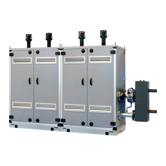
DEVICE DESCRIPTION INTRODUCTION BOX ErP.are.pre-mixed.condensation.he- designed.to.work.singularly.or.in.sequen- ating.modules.intended.only.for.heating,. ce/cascade.autonomously.. MURELLE EQUIPE 220-330-440-550 inter-connectible. and. easy. to. assemble,. DIMENSIONS MODULES 1.2.1 “MURELLEEQUIPE 220 BOX ErP” MURELLE EQUIPE 220 BOX ErP 1100 FIXTURES M.. System.supply.(Flange.PN6-DN100) R.. System.return.(Flange.PN6-DN100) G.. Gas.(Flange.PN6-DN50). S3. Condensation.drain.ø.40 NOTE: Assembly of a hydraulic separator or plate exchanger is also mandatory. The hydraulic separator is supplied with modules in a kit code 8101552 and the tubes connecting the hydraulic separator in the kit code 8101532. - Page 4 1.2.2 “MURELLE EQUIPE 330 BOX ErP” MURELLE EQUIPE 280-330 BOX ErP 1100 1730 FIXTURES M.. System.supply.(Flange.PN6-DN100) R.. System.return.(Flange.PN6-DN100) G.. Gas.(Flange.PN6-DN50). S3. Condensation.drain.ø.40 NOTE: Assembly of a hydraulic separator or plate exchanger is also mandatory. The hydraulic separator is supplied with modules in a kit code 8101552 and the tubes connecting the hydraulic separator in the kit code 8101532.
- Page 5 1.2.3 “MURELLE EQUIPE 440-550 BOX ErP” MURELLE EQUIPE 370-440 BOX ErP 2200 MURELLE EQUIPE 0 BOX ErP 2830 FIXTURES M.. System.supply.(Flange.PN6-DN100) R.. System.return.(Flange.PN6-DN100) G.. Gas.(Flange.PN6-DN50). S3. Condensation.drain.ø.40 NOTE: Assembly of a hydraulic separator or plate exchanger is also mandatory. The hydraulic separator is sup- plied with modules in a kit code 8101553 and the tubes connecting the hydraulic separator in the kit code 8101533.
- Page 6 TECHNICAL SPECIFICATIONS MURELLE EQUIPE 220 BOX ErP 330 BOX ErP 440 BOX ErP 550 BOX ErP Generators with a heat output kW 105.4. n°. Heat output Nominal.(80-60°C).(Pn.max). 210.8. 316.2. 421.6. 527.0 Nominal.(50-30°C).(Pn.max). 225.2. 337.8. 454.0. 563.0 Minimum.(80-60°C).(Pn.min). 20.8. 20.8. 20.8. 20.8 Minimum.(50-30°C).(Pn.min).
- Page 7 OPERATING DIAGRAM (fig. 2) 19.. ----------.. . 1. Cascade.supply.probe..(SMC) 20.. ----------.. . 2. Hydraulic.compensator 21.. ----------.. . 3. ----------.. 22.. 3-way.drain.tap . 5. Condensation.drain.siphon 23.. System.supply.tap . 6. Gas.valve 24.. Single.module.drain . 7. ----------.. 25.. Gas.tap . 8. Fan 26.. 8.litre.expansion.tank .
- Page 8 MAIN COMPONENTS (fig. 3) Codice/Code 8111271 Modello/Model MURELLE EQUIPE 220 BOX ErP Matricola/Serial n. 9999999999 PAR 1 = 8 (G20) / 16 (G31) PAR 2 = 9 . 1. System.return.manifold . 2. Gas.tap . 3. System.supply.manifold . 4. Gas.valve . 5. Fan 6.
-
Page 9: Installation
INSTALLATION Installation. is. permanent. and. must. –. Double.box.(size:.1100.x.790.x.1600).for. outdoor. installations,. see. points. 2.6,. 2.7. exclusively. be. performed. by. specialised. hydraulic.separator.code.8101527 and.2.10.in.this.manual. and.qualified.personnel,.following.all.the. –. Hydraulic. separator. kit. code. 8101552. instructions. and. provisions. included. in. for. modules. “220-330 BOX ErP”. and. INSTALLATION code. - Page 10 SYSTEM CONNECTIONS invalidates the device’s warranty. 2.3.2 Filter on the gas pipe Gas.connections.must.be.made.in.accor- To. protect. the. heat. system. from. dama- dance.with.current.standards.and.regu- The.gas.valve.is.supplied.ex.factory.with. ging. corrosion,. incrustation. or. deposits,. lations.. When. dimensioning. gas. pipes. an. inlet. filter,. which,. however,. is. not. after. installation. it. is. extremely. impor- from.
- Page 11 INDOOR INSTALLATION The.indicated.solutions.have.the.exhaust. NOTE: The kits are purposely treated EXHAUST KIT manifold. (available. separately). positio- also to resist weathering when installed (fig. 6 - 6/a - 6/b) ned.on.the.module’s.to.right.. outdoors. It. is. however. possible. to. move. the. In these cases the compensator and Refer.
- Page 12 MURELLE EQUIPE 440 BOX ErP MURELLE EQUIPE 370-440 BOX ErP exhaust manifold kit con kit collettore fumi code 8102532 cod. 8102532 ø. MURELLE EQUIPE 440 BOX ErP MURELLE EQUIPE 370-440 BOX ErP (with box container for hydraulic separator (con box contenitore per separatore idraulico code 8101527) e kit sicurezze INAIL cod.
- Page 13 MURELLE EQUIPE 550 BOX ErP MURELLE EQUIPE 550 BOX ErP exhaust manifold kit con kit collettore fumi code 8102533 cod. 8102533 ø .200 MURELLE EQUIPE 550 BOX ErP MURELLE EQUIPE 550 BOX ErP (con box contenitore per separatore idraulico (with box container for hydraulic separator e kit sicurezze INAIL cod.
- Page 14 TUBES CONNECTING THE HYDRAULIC SEPARATOR KIT (fig. 7 - fig. 7/a) Tubes. connecting. the. hydraulic. separator. kit. code. 8101532. supplied. as. option. for. “MURELLE EQUIPE 220-330 BOX ErP”. models.it.is.formed.(fig..7): –..System. supply. flanged. section. code. 6291968 –..System. return. flanged. section. code. 6291968 –..Gaskets,.nuts.and.fastening.screws.M16 –..Expansion.
- Page 15 RS-485 BOARD (fig. 8) nication.of.at.least.two.boilers.in.cascade. equipped.with.lid.to.the.RS-485.board. and. is. performed. by. requesting. another. already.installed.in.the.MASTER.boiler. Each.module.is.supplied.with.the.RS- 485. RS-485. board. provided. in. the. kit. code. (boiler.with.PAR 15 = 0).with.the.wired. board. which. allows. you. to. manage. the. 8092244.. connector.provided.in.the.kit. ATTENTION: Communication will occur CAUTION: Insert the wired connector boilers.in.sequence/cascade.
- Page 16 CONNETTORE CABLATO (cod. 6319173) WIRED CONNECTOR (cod 6319173) DIP SWITCH IP SWITCH GESTIONE IN MODBUS ESTIONE IN CASCATA MODBUS MANAGEMENT ASCADE MANAGEMENT 1 2 3 COMUNICAZIONE MODBUS MODBUS COMMUNICATION INSTALLER PARAMETER SETTING: PAR 16 MODBUS ADDRESS --..=.Not.enabled 1...31.=.Slave.from.1.to.31 (ATTENTION: Avoid calling the boiler with the same number assigned to either appliances) PAR 17 MODBUS CONFIGURATION --..=.Not.enabled...
- Page 17 TABELLA DELLE VARIABILI MODBUS / MODBUS BOILER VARIABLES LIST Descrizione / Function Variable description Digital variables (COILS) Boiler CH Enable/Request D R/W Richiesta riscaldamento zona 1 Request CH zone 1 Boiler DHW Enable D R/W Abilitazione preparazione ACS Enable DHW preparation Boiler Water Filling Function D R/W Non usato...
- Page 18 2.10 SYSTEM AVAILABLE HEAD (fig. 9) The.head.available.of.the.generator.sup- ply/return. manifolds. vs.. the. flow. rate. is. shown.on.the.chart.of.figure.9.. SYSTEM AVAILABLE HEAD 2.10.1 Load loss hydraulic separator Hydraulic.separator.load.losses.are.indi- cated.in.the.diagram.in.fig..9. WARNING: The hydraulic separator can be inserted in a specific protective box code 8101527 supplied separately. 2.10.2 Hydraulic separator “220-330 BOX ErP”...
- Page 19 CONNECTIONS 230V. –. 50. Hz. single. phase. voltage. is. required. using. a. fuse. protected. main. NOTE: SIME shall not be liable for any Each. module. is. supplied. with. a. power. switch. with. at. least. 3. mm.. between. damages to persons and things due to lack of boiler grounding.
- Page 20 2.11.2 Electrical connection of modules in sequence/cascade (fig. 11/a) Line Neutral External.sensor SMC. Cascade.supply.probe RS-485. Cascade.management.board NOTICE: The external temperature probe (SE) must be connected to the MASTER boiler and the cascade supply probe (SMC) to the SLAVE 1 boiler. The SE, SMC probes and the RS-485 board connection cable are supplied together with the modules in the probe kit code 8092250.
-
Page 21: Features
ON/OFF KEYS (access to INST and OEM parameters) ON.=.. Electricity.supply.to.boiler.is.on PC CONNECTION OFF.=.. Electricity. supply. to. boiler. is. on. but. nor. To.be.used.only.with.the.SIME.programming.kit.and.only. ready. for. functioning.. However,. the. protec- by.authorised.personnel..Do.not.connect.other.electronic. tion.functions.are.active. devices. (cameras,. telephones,. mp3. players,. etc.). Use. a. SUMMER MODE KEY tool.to.remove.the.cap.and.reinsert.after.use. - Page 22 ACCESS TO INSTALLER’S INFORMATION For.access.to.information.for.the.installer,.press.the.key. .(3.fig...14)..Every.time.the.key.is.pressed,.the.display.moves.to.the.next. item.of.information..If.the.key. .is.not.pressed,.the.system.automatically.quits.the.function..If.there.is.no.expansion.board.(ZONA.MIX. or.INSOL).the.relative.info.shall.not.be.displayed..List.of.information: 1.. Visualisation. of. external. temperature,. 9.. Visualisation.fan.speed.in.rpm.x.100.(e.g..4.800.and.1850.rpm) 1...Visualizzazione.temperatura.esterna 9...Visualizzazione.numero.giri.ventilatore.in.rpm.x.100.(es..4.800.e.1.850.rpm) only.with.external.sensor.connected ..solo.con.sonda.esterna.collegata 2...Visualizzazione.temperatura.sonda 2.. Visualisation.of.C.H..flow.sensor.(SM) 10..Visualisation.of.hours.of.functioning.of.the.burner.in.h.x.100.(e.g..14000.and.10) 10...Visualizzazione.ore.di.funzionamento.del.bruciatore.in.h.x.100.(es..14.000.e.10) ..mandata.riscaldamento.(SM) 3.. Visualisation. of. D.H.W.. temperature. sen- 3..Visualizzazione.temperatura.sonda 11...Visualisation.of.number.of.times.the.burner.has.ignited.x.1000.(e.g..97000.and.500) 11...Visualizzazione.numero.di.accensioni.del.bruciatore.x.1.000.(es..97.000.e.500) ..sanitario.(SS).solo.per.caldaie.istantanee sor.(SS).only.for.instantaneous.boilers 4.. Visualisation. of. auxiliary. temperature. 12..
- Page 23 18..Visualisation.C.H..return.sensor.value.(SR) 29.. Visualisation.valve.closing.opening.control.with.board.ZONA.MIX. 18. .Visualizzazione.valore.sonda.ritorno.riscaldamento.(SR) 29. .Visualizzazione.comando.chiusura.valvola.con.schedino 2..(respectively.ON.and.OFF) ..ZONA.MIX.2.(rispettivamente.ON.e.OFF) 19..Visualisation.collector.probe.value 30..Visualisation. solar. probe. temperature. value. S1. with. 30. .Visualizzazione.valore.temperatura.sonda.solare.S1 19. .Visualizzazione.valore.sonda.collettore.cascata ..con.schedino.solare.INSOL solar.board.INSOL 20..Visualisation. delivery. probe. value. mixed. with. board. 31..Visualisation. solar. probe. temperature. value. S2. with. 31...Visualizzazione.valore.temperatura.sonda.solare.S2 20. .Visualizzazione.valore.sonda.mandata.impianto.miscelato ZONA.MIX.1.(input.S2) ..con.schedino.solare.INSOL solar.board.INSOL...
- Page 24 6.=.Zone.2.valve. with.the.keys. . and. Luminous.bar.indicating.presence. 0.=.Disabled. The.standard.visualisation.returns.auto- of.voltage. 1.=.Enabled matically. after. 60. seconds,. or. by. pres- Allocation.of.SIME.HOME.channels... 0.=.Not.assigned. 1.=.Circuit.1. sing. one. of. the. control. keys. (2. fig.. 12). es..14.000.e.10) 2.=.Three-zone.circuit excluded.the.key.RESET. Fan.rpm.Step.ignition. 0,0..81. rpmx100. 0,1 from.0,1.to.19,9.
- Page 25 BOILER PAR 2 PARAMETERS INSTALLER Instant.with.deviator.valve.. and.flowmeter EXPANSION CARD Instant.with.deviator.valve,.. .flowmeter.and.solar.combination PAR.DESCRIPTION... RANGE. UNIT.OF. INC/DEC.. DEFAULT MEASUREMENT. UNIT. SETTING D.H.W..tank.with. Number.of.expansion.boards.. 0..3. .deviator.valve.and.boiler.sensor.. Mix.valve.stroke.time. 0..199. 10.sec.. vers..T.(LOW.INERTIA). Priority.of.D.H.W..over.mixed.zone. 0.=.Paralle. 1.=.Absolute On.board.D.H.W..tank.with Floor.drying. 0.=.No.activated. .deviator.valve.and.D.H.W..sensor... (LOW.INERTIA). 1.=.Curve.A 2.=.Curve.B . R emote.D.H.W..tank.with.deviator. 3.=.Curve.A+B .
- Page 26 –. Interface. with. the. following. elec- or. by. a. broken. valve. coil. (the. inter- 4.161 tronic. systems:. remote. control. ruption.does.not.allow.for.opening).. 3.021 SIME.HOME.code. 8092280/81,. ther- 2.229 mal. regulator. RVS,. connected. to. a. –. The electrode does not discharge. 1.669 management. card. of. a. mixed. zone.
- Page 27 1200 1200 1600 1500 2000 2000 2400 2500 2800 3000 3200 3500 3600 4000 4000 4082 nection.points..The.electrode.is.con- When. voltage. returns,. the. boiler. will. is. shown. as. a. function. of. rate. of. flow. nected. to. the. earth. or. badly. worn. automatically.start.up.again. in.
-
Page 28: Use And Maintenance
.ionizzazione.in.µA ..OEM.(es..48.accessi) GAS CONVERSION (fig. 17) MAX power funzionamento.del.bruciatore.in.h.x.100.(es..14.000.e.10) (Methane) (Propane) This operation must be performed by 9,0.±0,3. 10,2.±0,3 authorised personnel using original Sime components. 4). Press.the.button.for.a.few.seconds. The. standard. display. will. automatically. To.convert.from.natural.gas.to.LPG.or.vice. return.after.10.seconds.. 5). Identify.the.CO ro.di.accensioni.del.bruciatore.x.1.000.(es..97.000.e.500) .values.at.min..power.by. versa,.perform.the.following.operations The.table.below.shows.the.SET.settings.to. - Page 29 is particularly important if the generator has not been used for extended periods of time). If necessary, the drip plate can be filled using the tap provided (fig. 20). Fig..21 ZONA MIX code 8092234.. demands. are. ignored. (heating,. sanitary,. antifreeze.and.chimney.sweep).. The.
- Page 30 FUNCTIONING ANOMALIES Apre Circuito When. there. is. a. functioning. anomaly,. an. Circuito riscaldamento 2 alarm.appears.on.the.display.and the blue riscaldamento 2 luminous bar becomes red. Descriptions.of.the.anomalies.with.relative. alarms.and.solutions.are.given.below: –. LOW WATER PRESSURE ANOMALY ALARM 02 (fig. 23/1) Circuito Circuito If.the.pressure.detected.by.the.transdu- riscaldamento 3 riscaldamento 3 (impianto tre Fig..23/1 cer.
- Page 31 Apre –. SAFETY/LIMIT THERMOSTAT ANO- MALY ALARM 07 (fig. 23/6) If.the.connection.with.the.safety.ther- Circuito mostat/limit. thermostat. is. interrup- riscaldamento 2 ted,.the.boiler.will.stop;.the.flame.con- trol.will.remain.waiting.to.be.switched. off.for.one.minute,.keeping.the.system. pump.on.for.that.period.. . If,. the. thermostat. connection. is. re- stored. within. the. minute,. the. boiler. Circuito Circuito will. start. up. working. normally. again,. riscaldamento 3 riscaldamento 2 otherwise.
- Page 32 riscaldamento 3 (impianto tre zone) rcuito –. “ALL 15” FAN ERROR (fig. 23/12) –. SAFETY THERMOSTAT INTERVEN- –. AUXILIARY SENSOR ANOMALY (S3) scaldamento 2 Circuito . The.fan.speed.does.not.fall.within.the. TION SECOND MIXED ZONE “ALL 22” “ALL 26” (fig. 23/20) riscaldamento 2 rated.speed.range.. (fig.
- Page 33 Apre CAUTION: In the event of sequence/ca- tion.is.activated scade connection, error codes 70 and 71 will appear on the SIME HOME remote control display: - ALARM 70 When an anomaly affects cascade operation (cascade delivery sensor...
- Page 34 USER INSTRUCTIONS WARNINGS – In case of failure or malfunction of the equipment, contact authorised technical staff. – For safety reasons, the User cannot access the internal parts of the appliance. All operations involving the removal of protections or otherwise the access to dan- gerous parts of the appliance must be performed by qualified personnel.
- Page 35 Request assistance from qualified technical personnel. If.the.boiler.is.not.used.for.a.prolonged.period,.it. is.advisable.to.disconnect.the.electricity.supply,. Fig..27/c by.switching.off.the.main.switch.of.the.system,. –. ALL 70 and ALL 71 These alarms appear on the SIME HOME and.to.close.the.gas.tap.and,.if.low.temperatures. are.expected,.to.completely.empty.the.hydraulic. remote control display. Request assistance circuits.to.avoid.pipes.being.broken.by.the.for- –. ALL 07 (fig. 27/d) from qualified technical personnel.
- Page 36 APPENDIX DETALLES DEL PRODUCTO / PRODUCT DETAILS 110 BOX 220 BOX 330 BOX 550 BOX 440 BOX Murelle Equipe Classe efficienza energetica stagionale riscaldamento Clase de eficiencia energética estacional en calefacción Classe de eficiência energética do aquecimento ambiente sazonal C.H. energy efficiency class Potenza termica (kW) Potencia térmica (kW) Potência calorífica (kW)
- Page 37 Daily fuel consumption Recapiti / Datos de contacto Fonderie Sime S.p.A. Via Garbo 27, 37045 Legnago (VR) ITALIA Elementos de contacto / Contact details a. Regime ad alta temperatura: temperatura di ritorno di 60°C all’entrata e 80°C di temperatura di fruizione all’uscita dell’apparecchio b.
- Page 38 Daily electricity consumption Recapiti / Datos de contacto Fonderie Sime S.p.A. Via Garbo 27, 37045 Legnago (VR) ITALIA Elementos de contacto / Contact details a. Regime ad alta temperatura: temperatura di ritorno di 60°C all’entrata e 80°C di temperatura di fruizione all’uscita dell’apparecchio b.
- Page 39 Daily electricity consumption Recapiti / Datos de contacto Fonderie Sime S.p.A. Via Garbo 27, 37045 Legnago (VR) ITALIA Elementos de contacto / Contact details a. Regime ad alta temperatura: temperatura di ritorno di 60°C all’entrata e 80°C di temperatura di fruizione all’uscita dell’apparecchio b.
- Page 40 Daily fuel consumption Recapiti / Datos de contacto Fonderie Sime S.p.A. Via Garbo 27, 37045 Legnago (VR) ITALIA Elementos de contacto / Contact details a. Regime ad alta temperatura: temperatura di ritorno di 60°C all’entrata e 80°C di temperatura di fruizione all’uscita dell’apparecchio b.
- Page 41 NOTES...
- Page 42 NOTES...
- Page 43 NOTES...
- Page 45 Fonderie.Sime.S.p.A..-..Via.Garbo,.27..-..37045.Legnago.(Vr). Tel..+.39.0442.631111.-..Fax.+39.0442.631292..-..www.sime.it...
Need help?
Do you have a question about the MURELLE EQUIPE 220 BOX ErP and is the answer not in the manual?
Questions and answers